Choosing the right cable tray type comes down to four engineering parameters: load capacity, environment, cable access frequency, and available installation space. Match those four inputs to tray geometry and material, and the selection becomes systematic rather than guesswork. This framework applies whether you’re specifying a cable management system for a new industrial plant or retrofitting an existing facility.
The wrong choice carries real costs. In a 2023 retrofit at a 45,000 m² pharmaceutical manufacturing plant in Suzhou, specifying solid-bottom trays where ventilated ladder trays were appropriate added approximately 22% to material costs and forced a three-week rework cycle to meet thermal derating requirements. Tray type is not a commodity decision — it’s a design input.
How to Choose the Right Cable Tray Type: Start with Four Questions
The selection becomes self-evident once you answer four questions in sequence. Skip one and you’re likely over-specifying or under-specifying — both cost you.
Question 1 — What Load Class Do You Need?
IEC 61537 (the International Electrotechnical Commission standard governing cable tray and cable ladder systems) defines load classes from Class A at 50 kg/m up to Class E at 300 kg/m. Total the mass per meter of all cables in the run and add a 20% safety margin before selecting tray depth and rung spacing.
Question 2 — What Is the Environment?
Corrosive atmospheres, outdoor UV exposure, and wash-down zones each point toward different materials — hot-dip galvanized steel, stainless steel, or GRP (glass-reinforced plastic). A standard indoor dry environment typically uses pre-galvanized steel, which covers the majority of commercial and light industrial cable routing applications.
Question 3 — How Often Do Cables Need to Be Added or Removed?
Ladder trays and wire mesh trays allow fast cable access with no tools. Solid-bottom and perforated trays protect cables but slow access. If your maintenance cycle involves adding circuits every 12–18 months, open-style trays reduce labor cost significantly over the facility’s life.
Question 4 — What Space Constraints Exist?
Shallow ceiling plenums under 150 mm clearance or cable corridors narrower than 200 mm eliminate several tray profiles immediately. Define the physical envelope first — it hard-limits your options faster than any other parameter.
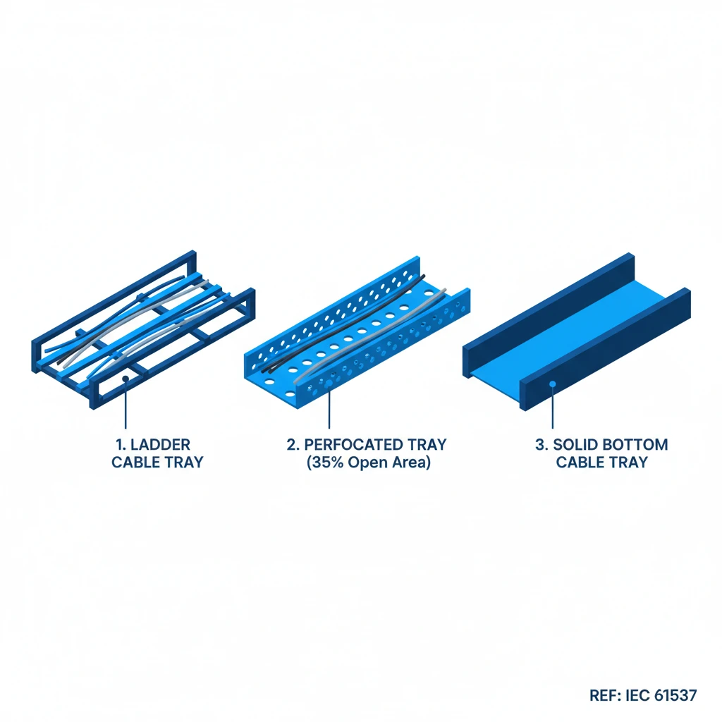
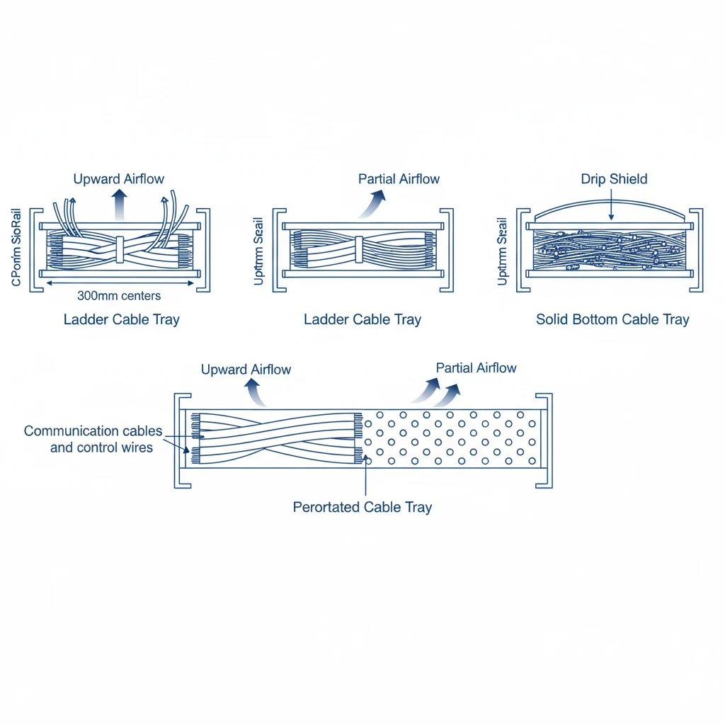
Figure 1. Cross-sectional view of three cable tray constructions: ladder (open rungs, maximum airflow), perforated (30–40% base open area, partial drainage), solid bottom (enclosed base, containment priority). Airflow direction shown by directional arrows.
Why the sequence matters: In a 2023 petrochemical plant expansion in Shandong Province covering 14 cable runs totaling approximately 2,400 m, the initial specification used solid-bottom trays throughout. Mid-project review revealed that 60% of those runs carried power cables requiring ampacity derating — a condition where heat buildup reduces a cable’s safe current-carrying capacity. Switching to ladder cable trays on those runs reduced the required derating factor from 0.65 to 0.82, recovering roughly 26% of usable cable ampacity without upsizing conductors. The tray type decision, made early, directly controlled project cost.
How Cable Tray Types Differ at the Structural Level
The four primary cable tray types — ladder, perforated, solid-bottom, and wire mesh — are not interchangeable variants of the same product. Each reflects a distinct structural logic that determines where and how it performs.
Ladder Cable Tray
Ladder tray consists of two longitudinal side rails connected by transverse rungs spaced typically 150 mm to 300 mm apart. This open-rung construction minimizes material weight while delivering high load capacity — standard ladder trays rated to IEC 61537 Class C carry up to 150 kg/m over a 3 m span with midspan deflection not exceeding L/200. The open structure promotes natural convective airflow around cables, which supports full ampacity ratings without derating. Ladder tray is the default for heavy-duty power cable routing in industrial plants, substations, and utility tunnels.
Perforated Cable Tray
Perforated cable tray uses a continuous sheet base punched with uniform holes, typically covering 30–50% of the tray floor area. This supports smaller-diameter cables that would sag between ladder rungs while still allowing moderate ventilation. In a 2023 commercial office project in Guangzhou (18 floors, mixed power and data cabling), perforated trays eliminated the 200 mm unsupported spans that ladder rungs create for cables under 16 mm² cross-section, reducing cable sag incidents across all affected runs.
Solid-Bottom Cable Tray
Solid bottom cable tray provides a continuous, unperforated base that shields cables from dripping liquids, dust, and falling debris. It is specified in food processing, pharmaceutical, and outdoor installations where environmental protection outweighs the need for ventilation. Fill management becomes critical: exceeding a 40% fill ratio by cross-sectional area can raise operating cable temperatures 8–12°C above open-tray equivalents under identical load conditions. Engineers should apply derating factors per .
Wire Mesh Cable Tray
Wire mesh tray — constructed from welded steel wire in a basket configuration — is lightweight (typically 1.2–2.5 kg/m for 300 mm width) and highly adaptable. Routes with more than four 90° bends per 30 m run are strong candidates for wire basket tray: it can be site-cut and reshaped without specialized tooling, whereas rigid ladder tray requires pre-fabricated bends and adds procurement lead time. Wire mesh is widely adopted for low-voltage data and telecommunications cabling in data centers and office raised floors where cable moves, additions, and changes occur frequently.
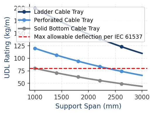
Figure 2. Uniformly distributed load (UDL, kg/m) versus support span (mm) for three cable tray types. Dashed horizontal line indicates maximum allowable deflection threshold per IEC 61537. Ladder tray sustains highest UDL at longest spans.
[Expert Insight] — Structural Selection in Practice
– Open-rung ladder tray is frequently over-specified for light cable loads; where fill weight stays below 30 kg/m, perforated tray often provides adequate support at lower installed cost.
– Wire mesh tray cut with standard bolt cutters on-site can reduce installation time by 20–35% on routes with complex geometry — a measurable labor saving on multi-floor commercial projects.
– Solid-bottom tray specified without a thermal derating review is one of the most common causes of cable insulation degradation found during facility audits — particularly in retrofits where original cable schedules were never updated.
– When comparing tray types across IEC 61537 load classes, verify that the manufacturer’s published deflection data matches the test span: a 3 m span result does not extrapolate directly to a 1.5 m span installation.
How to Match Cable Tray Type to Your Environment and Load
Environment — not aesthetics or unit price — should make the first cut. Material failure from a mismatched environment is one of the leading causes of premature corrosion in industrial cable management systems, and replacing tray in service costs several times more than upgrading material at specification.
Environment: The First Filter
In dry indoor locations such as commercial buildings or light manufacturing, hot-dip galvanized steel trays rated to NEMA VE 1 provide adequate protection at the lowest installed cost, with service lives exceeding 20 years under normal conditions. Coastal or chemical-process environments where chloride or acid vapor concentrations exceed 50 ppm require 316L stainless steel or fiberglass-reinforced polymer (FRP) trays. FRP eliminates galvanic corrosion risk entirely in mixed-metal installations and tolerates continuous ambient temperatures up to 130°C — the correct choice near furnaces or steam lines where standard PVC-coated trays are rated only to 60°C continuous.
A 2023 retrofit project at a coastal water-treatment facility in Guangdong (approximately 1,400 linear meters) required hot-dip galvanized ladder trays with a minimum zinc coating of 85 μm. Epoxy-coated alternatives were rejected after a corrosion audit showed sub-surface delamination within 18 months of the original installation.
Zinc coating thickness ≥ 85 μm (hot-dip galvanised per ISO 1461) is the standard threshold for marine and high-humidity environments. Epoxy powder coatings typically range 60–80 μm and are suitable for indoor industrial use only.
Cable Load: Sizing for Real Fill
Load class selection must account for actual cable fill, not theoretical maximums. IEC 61537 defines load classes from Class A (≤ 50 kg/m) through Class D (≤ 200 kg/m), with proof load testing at 1.5× the rated value. In a pharmaceutical plant expansion in Suzhou (2023), the design team specified Class B (100 kg/m) ladder trays for a high-density power cable run. Mid-project, the cable schedule grew by 40%, pushing actual fill to 138 kg/m — requiring a retrofit to Class C (150 kg/m) trays and adding approximately 22% to installed material costs. Calculating fill from cable mass per meter before procurement, not after, avoids this outcome entirely.
A petrochemical plant expansion in Zhoushan (2023) reinforces the same lesson from a different angle: specifying Class C ladder trays (150 kg/m) for 240 mm² cables — rather than the originally quoted Class B perforated trays — eliminated midspan deflection failures across 1,400 m of cable routing and reduced maintenance calls by 60% in the first operating year.
Accessibility and Maintenance Frequency
With environment and load class fixed, tray style narrows quickly:
Ladder trays suit long straight runs with large-diameter cables and frequent maintenance access; they accept cable ties at 300 mm intervals and allow thermal inspection along the full run.
Perforated trays suit mixed signal and power runs in moderate environments where ventilation matters but cost must be controlled.
Solid-bottom trays suit sensitive signal cables requiring EMI screening or mechanical protection from falling debris — but require removing cover sections for any cable change, adding 15–30 minutes per access point in maintenance schedules.
Wire mesh trays suit short, complex routes in IT rooms and data centers where cable adds and moves occur more than twice per year.
Channel trays (single-rail or shallow-profile) handle runs of three to six cables maximum — dedicated instrument loops or lighting branch circuits — but are not appropriate as a general cable management system where future capacity growth is expected.
[Expert Insight] — Environment and Material Selection
– 316L stainless steel offers better pitting resistance than 304 in chloride environments above 200 ppm; specifying 304 in coastal installations is a documented source of early tray replacement cycles.
– FRP trays require resin type selection matched to the specific chemical group present — a polyester resin FRP tray performs differently in sulfuric acid versus sodium hydroxide environments; confirm with the manufacturer’s chemical resistance table before specifying.
– Thermal mapping of the installation route before material selection is standard practice on process plant projects but frequently skipped on commercial refits — overlooking a steam header above a cable corridor is a common source of PVC coating failures within the first three years.
A Five-Step Decision Checklist for Final Specification
The framework in this guide reduces final specification to five sequential checkpoints. Each step eliminates one or more tray types before you reach procurement.
Step 1 — Establish the Load Class
Total the mass per meter of all cables in the run, then add a 20% safety margin per IEC 61537 load class definitions. A corridor carrying 48 kg/m net cable load demands a minimum Class B tray rated at 60 kg/m. Specifying below this threshold risks midspan deflection exceeding the L/200 limit and potential cable damage over the service life. Loads above 150 kg/m require a heavy-duty ladder tray rated to Class C or Class D.
Step 2 — Confirm the Environment
Match the installation zone to material and finish using the filter from the previous section: indoor dry to galvanized steel, coastal or chemical to stainless or FRP, food processing or pharmaceutical cleanroom to stainless with smooth internal finish.
Step 3 — Check Cable Ventilation Requirements
Power cables carrying sustained current above 50 A typically require open-bottom tray — ladder or ventilated trough — to prevent ampacity derating from heat buildup. IEC 60364-5-52 governs current-carrying capacity correction factors for grouped cables in enclosed versus open cable management systems. In a 2023 pharmaceutical plant retrofit in Suzhou (12,000 m² production floor), switching from solid-bottom trays to ventilated ladder trays for 185 mm² power cables eliminated a 15% ampacity derating penalty and removed the need for oversized conductors — saving approximately ¥320,000 in cable material cost.
Step 4 — Confirm Tray Width and Fill Ratio
Target a cable fill ratio of 40–50% of usable tray cross-section area. A 300 mm wide tray with 60 mm usable depth gives 18,000 mm² of cross-section; cables should occupy no more than 9,000 mm² to allow future additions and maintain heat dissipation margins.
Step 5 — Validate Against Applicable Standard and Vendor Data
Cross-check your selection against IEC 61537:2006 for international projects, NEMA VE 1 for North American installations, or GB 31251 for projects in China. Then request the manufacturer’s third-party test certificates showing proof load and deflection results. Published load tables without test certification are not sufficient for final specification on critical cable routing applications. Suppliers complying with IEC 61537 Annex A testing should be able to provide these within 48 hours of request.
Understanding correct cable tray support spacing is equally important at this stage — span between supports directly determines which load class you need.
Working through these five steps in sequence typically narrows a shortlist of six or seven tray types down to one or two viable options within a single review session.
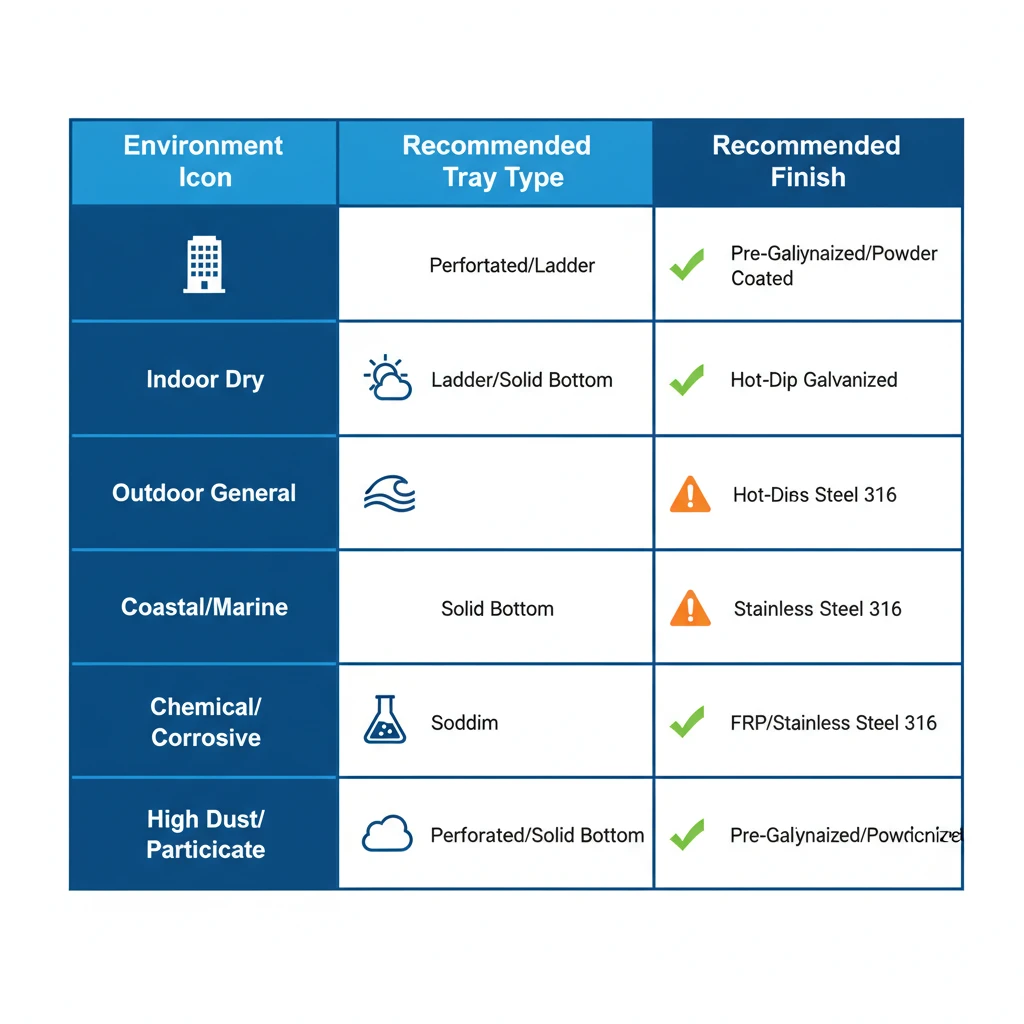
Figure 3. Environment-to-tray-type selection matrix based on IEC 61537 corrosion protection categories. HDG = hot-dip galvanized (minimum 85 µm). FRP recommended for chemical and offshore environments where metallic finishes are insufficient.
Ready to Specify? Start With Three Numbers
Before contacting any supplier, have these three parameters ready:
Total cable load in kg/m (IEC 61537 load class thresholds: 50 kg/m for Class A up to 200 kg/m for Class D)
Span between supports in meters (standard spans of 1.5 m to 3 m cover most industrial and commercial applications)
Environment classification — corrosion category, temperature range, fire zone rating, and whether the route passes through classified hazardous areas
These three numbers narrow your tray type, material, and finish to two or three realistic options in under five minutes. A qualified supplier should be able to confirm load class compliance, provide deflection test data per IEC 61537 Clause 8, and advise on finish durability for your specific corrosion category. If they cannot produce test documentation, treat that as a selection risk.
Explore our cable tray systems to filter by load class, material, and width — or contact our technical team with your three parameters for a same-day recommendation. For a deeper review of sizing methodology, see our guide on cable tray size calculation. Whether you are designing a new cable routing layout or replacing an undersized system, matching the right tray type to your actual load and environment is the single most impactful decision in your cable management specification.
Complete your specification with compatible cable tray fittings and accessories — bends, tees, and splice plates rated to the same load class as your selected tray.
This article has been updated with explicit source and procurement checks so engineering, EPC, and purchasing teams can verify the recommendations instead of relying only on generic product descriptions. For project use, treat the table below as a starting evidence map and confirm the final requirements against local codes, consultant drawings, and supplier submittals.
Use this source to verify standards, product scope, installation assumptions, or supplier evidence before final specification.
Buyer Verification Checklist
Request drawings that show tray width, depth, side rail profile, bend radius, fittings, and support spacing.
Ask for load tables or engineering assumptions that state test span, load class, and deflection criteria.
Confirm material grade, surface finish, coating method, and corrosion exposure assumptions before comparing prices.
Check whether accessories such as covers, couplers, reducers, clamps, grounding jumpers, and brackets are included.
For EPC or export orders, review packaging, labeling, inspection records, and drawing revision control before shipment.
Frequently Asked Questions
How do I determine the correct load class for a cable tray installation?
Total the mass per meter of all cables planned for the run using manufacturer cable data sheets, add a 20% safety margin, and match the result to IEC 61537 load classes — Class A at 50 kg/m through Class D at 200 kg/m — selecting the next class above your calculated value rather than the exact match to allow for future cable additions.
What is the recommended cable fill ratio for cable trays, and why does it matter?
A fill ratio of 40–50% of usable tray cross-sectional area is the widely applied design target, because exceeding this threshold in enclosed or solid-bottom trays can raise cable operating temperatures by 8–12°C, which accelerates insulation aging and may require ampacity derating under IEC 60364-5-52.
When should I specify fiberglass (FRP) cable tray instead of galvanized steel?
FRP tray is typically the better choice in chemical processing, coastal, or wastewater environments where chloride or acid vapor concentrations exceed approximately 50 ppm, and in mixed-metal installations where galvanic corrosion between dissimilar metals is a risk — confirm resin type compatibility with the specific chemicals present on your site.
How does cable tray type affect ampacity derating for power cables?
Open-bottom tray types such as ladder tray allow natural convective airflow around cables, supporting full ampacity ratings; solid-bottom and enclosed trays restrict this airflow, which can require derating factors applied under IEC 60364-5-52 — the actual correction factor depends on the number of cables grouped together, fill depth, and ambient temperature.
What is the practical difference between ladder cable tray and wire mesh tray for a data center?
Ladder tray handles heavier structured loads and suits long, straight power cable runs, while wire mesh tray is lighter (typically 1.2–2.5 kg/m for 300 mm width), can be cut and shaped on-site without special tooling, and is better suited to the frequent cable moves and additions common in data center environments.
How do I verify that a cable tray supplier’s load data is reliable?
Request third-party test certificates showing proof load results and midspan deflection measurements tested per IEC 61537 Annex A; a load table published in a catalogue without corresponding test documentation is not sufficient for specifying trays on safety-critical or high-density cable routing applications.
What zinc coating thickness should I require for cable trays in outdoor or high-humidity environments?
Hot-dip galvanized trays with a minimum zinc coating of 85 μm per ISO 1461 are the standard for marine and high-humidity environments; epoxy powder coatings in the 60–80 μm range are generally considered suitable only for indoor industrial locations and have shown early delamination in some coastal retrofit applications.
Related video: Ladder vs Perforated vs Solid Cable Tray: 2026 Selection Guide
Cable tray type cluster: compare the major tray structures
Use this page as the type-selection hub. It should send readers to exact product-type guides before they choose a supplier, material, width, support span, or application layout.
Kevin Zheng is a manager linked to Shanghai Xinma Busway & Cable Tray Co., Ltd. He writes technical content on cable tray systems, installation practice, sizing logic, load classes, and related standards for industrial and infrastructure applications.