Video overview: key engineering checks before selecting this cable tray system.
What Is Perforated Cable Tray? Construction, Function, and Selection Guide
Perforated cable tray is a continuous, ventilated cable management channel fabricated from sheet metal — typically steel or aluminum — with punched holes or slots across its base and sidewalls. It sits between solid-bottom tray and open ladder tray in the cable management hierarchy, offering a continuous support surface with controlled airflow. Understanding how it’s built and why the perforations matter is the foundation for selecting the right system.
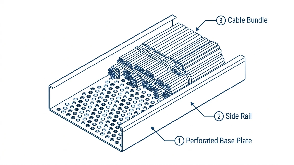
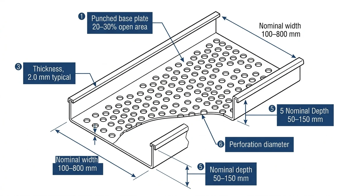
Figure 1. Cross-sectional detail of perforated cable tray showing punched base plate with 20–30% open area, upturned side rails with return flanges, and key nominal dimensions — construction basis for IEC 61537 load class testing.
What Is Perforated Cable Tray?
A perforated cable tray is a shallow U-channel formed from sheet metal, with a flat perforated base pan flanked by two side rails. Standard widths follow the IEC 61537 preferred series: 50, 100, 150, 200, 300, 400, 500, and 600 mm. Depths typically run 25–100 mm. Perforation patterns vary by manufacturer but generally cover 30–50% of the base surface area — a figure that governs both structural performance and thermal behavior.
Unlike ladder cable tray, which uses open rungs, perforated tray provides a continuous support surface. That makes it better suited for smaller-diameter cables, instrumentation wiring, and data cables that would sag or deform between rungs. Unlike solid-bottom tray, it allows passive airflow and drainage without any additional design intervention.
IEC 61537 — the International Electrotechnical Commission standard governing cable tray and cable ladder systems — classifies trays by load capacity. Perforated trays typically fall into Class A (50 kg/m) or Class B (100 kg/m) depending on gauge and span. The standard also defines a midspan deflection limit of L/200 under proof load, which engineers use to set support spacing — generally 1.5 m to 3 m depending on fill weight.
Common Materials
Galvanized steel: most common, suitable for general indoor and light industrial environments
Stainless steel (304 or 316L): used in corrosive, food-grade, or pharmaceutical environments
Aluminum: preferred where weight is a constraint, such as suspended ceiling installations
PVC-coated steel: applied in chemical processing areas where zinc coating alone is insufficient
Why Perforation Matters in Practice
The open area is not cosmetic. In a 2023 commercial office fit-out in Guangzhou covering 18,000 m² of raised-floor cabling, switching from solid-bottom trays to perforated trays with 40% open area reduced cable operating temperatures by an average of 6°C — allowing engineers to maintain full ampacity ratings without upsizing conductors. That translated to a 9% reduction in cable material cost across the project.
[Expert Insight]
– IEC 61537 load class ratings are span-dependent. A Class B tray rated at 100 kg/m over a 1.5 m span may only achieve Class A performance at 3 m — always verify against the manufacturer’s load table at your actual support spacing.
– Perforation ratio and load class interact: a 300 mm wide tray at 50% open area will have a lower rated load than the same tray at 30% open area, even at identical base metal thickness.
– For mixed cable types (power + data), perforated tray with a 150 mm minimum depth provides enough vertical separation to route segregated bundles side by side without a physical divider in many low-voltage applications.
– Tray deflection under full fill load should be checked at design stage, not just at commissioning — cable weight accumulates over the life of the installation as circuits are added.
How Perforated Cable Tray Is Manufactured
Perforated cable tray starts as flat sheet metal — cold-rolled steel, stainless steel, or aluminum alloy — fed through a progressive stamping press. The perforation pattern is punched before forming, so the sheet is stamped flat, then roll-formed into the final U-channel profile. This sequence matters: punching after forming would distort the hole geometry and compromise coating adhesion inside each cutout.
The Punching and Forming Process
Standard perforation patterns use round holes ranging from 5 mm to 20 mm in diameter, arranged in staggered or inline grids. The open-area ratio — the percentage of the base pan removed by holes — typically falls between 30% and 50% for commercial trays. Below 30%, airflow restriction reduces ampacity derating benefits. Above 50%, the remaining web material struggles to carry rated distributed loads without excessive deflection.
After punching, the sheet is roll-formed to create side rails — typically 50 mm or 100 mm in height depending on load class. Edges are deburred and flanged to eliminate sharp contact points that could damage cable insulation during pull-through. Standard section lengths are 2.4 m or 3 m.
Base metal thickness runs 1.0–2.5 mm depending on load class. Manufacturers compensate for the material removed by perforations through formed return flanges along tray edges and, in heavier-duty versions, a corrugated or ribbed base pattern between perforation rows — both of which restore bending stiffness without adding significant weight.
Surface Treatment and Corrosion Protection
Raw steel trays go through pre-treatment (phosphating or chromating) before hot-dip galvanizing or electrostatic powder coating. Hot-dip galvanized perforated trays achieve a zinc coating thickness of ≥ 45 μm per ISO 1461, which governs hot-dip galvanized coatings on fabricated iron and steel articles. Electro-galvanized or pre-galvanized sheet is used for indoor dry locations where a coating thickness of 12–20 μm is sufficient. Stainless steel grades 304 and 316L are passivated rather than coated, making them the standard choice for chemical, food-processing, and offshore environments.
In a 2024 petrochemical plant expansion in Shandong Province, specifying ISO 1461-compliant hot-dip galvanized trays in a Class C corrosion zone extended maintenance inspection intervals from 12 months to 36 months compared to the previously installed electroplated trays — a direct reduction in scheduled downtime.
Factory Testing Protocol
Before shipment, manufacturers test perforated cable tray against IEC 61537. A sample tray spanning 3 m is loaded to its rated uniform distributed load — for a Class B tray, that is 100 kg/m — and midspan deflection must not exceed L/200, or 15 mm for a 3 m span. Trays that pass proof load testing without permanent deformation exceeding 1 mm after load removal are marked with their load class and span rating.
This manufacturing and testing chain is what separates a compliant perforated cable tray from generic sheet metal channel — the geometry, coating, and verified load rating are all traceable to the finished product.
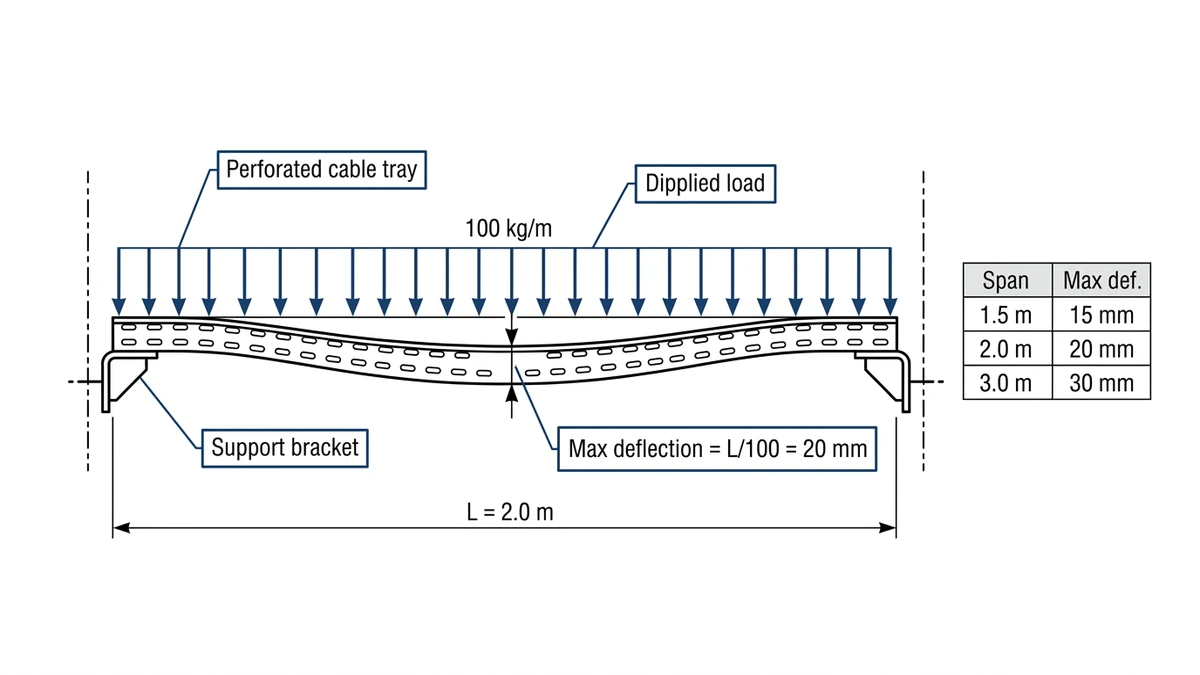
Figure 2. Load/span relationship for perforated cable tray under IEC 61537 test conditions, showing mid-span deflection at rated load. Maximum allowable deflection is L/100 of span length — a 2.0 m span permits no more than 20 mm deflection at mid-point under rated distributed load.
[Expert Insight]
– Hot-dip galvanizing per ISO 1461 is applied after fabrication, which means cut edges and punched hole interiors receive full zinc coverage — a meaningful corrosion protection advantage over pre-galvanized sheet, where cut edges are bare steel.
– Stainless steel 316L is specified over 304 when chloride exposure is likely (coastal sites, food processing with saline cleaning agents). The molybdenum content in 316L provides measurably better pitting resistance.
– Powder coating over galvanized steel (duplex coating) can extend service life by a factor of 1.5–2.5× compared to galvanizing alone in C3–C4 corrosion categories per ISO 12944.
– Always request the manufacturer’s IEC 61537 test certificate, not just a product datasheet — the certificate will specify the exact span and load combination under which the rating was verified.
What the Perforations Actually Do
The holes in a perforated cable tray serve three distinct engineering functions. Each one has a measurable effect on system performance.
Thermal Ventilation
Cables generate heat under load. In a fully enclosed raceway, that heat accumulates against the cable jacket, forcing engineers to apply ampacity derating factors. The open base of a perforated tray allows convective airflow across the cable bundle, reducing that derating penalty under .
In a 2023 data center fit-out in Shenzhen covering approximately 4,200 m² of cable tray installation, switching from solid-bottom tray to perforated tray with 40% open area allowed engineers to reduce the ampacity derating factor from 0.68 to 0.79 — recovering usable conductor capacity without upsizing cables. On a project with 180 cable runs, that eliminated the need to upsize any of them.
Weight Reduction
Removing 30–50% of the base material reduces tray self-weight by roughly 15–25% compared to a solid-bottom equivalent of the same gauge. On suspended installations — threaded rod hangers, strut channel, or beam clamps — that reduction directly lowers the structural load on building steel and can extend support spacing. In the 2024 Guangzhou office project referenced earlier, the switch to perforated tray reduced hanger loading by approximately 12%, simplifying coordination between electrical and structural teams.
Drainage
In outdoor or wet-area installations, standing water inside a solid tray accelerates corrosion of both the tray and cable jackets. Perforations allow water to drain passively. There is no additional design intervention required — the drainage function is inherent to the open base geometry.
Cable Tie and Label Access
A secondary benefit: the perforations provide anchor points for cable ties, identification tags, and separation barriers without drilling additional holes on site. This is particularly useful in retrofit installations where drilling into existing tray would compromise the coating.
One Tradeoff to Manage
Smaller cables — under approximately 10 mm diameter — can sag into larger perforations under their own weight across long unsupported spans. IEC 61537 addresses this indirectly through fill ratio and support spacing guidance. In practice, engineers typically limit support spacing to 1.5 m for lightweight cable bundles in perforated trays to prevent sag-induced stress at cable entry points. For a broader look at how support spacing is calculated across different tray types, the cable tray support guide covers the methodology in detail.
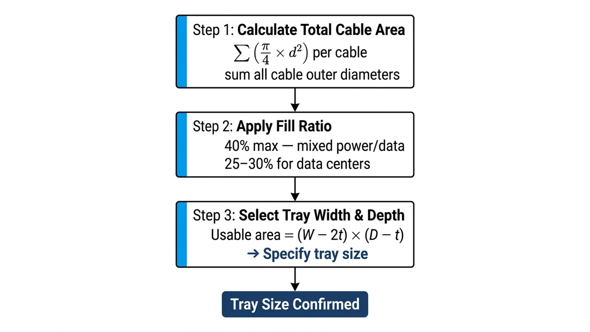
Figure 3. Three-step perforated cable tray sizing method per IEC 61537 fill ratio guidelines: calculate total cable cross-sectional area, apply 40% fill ratio, then select tray width and depth from usable area.
Selecting the Right Perforated Cable Tray
Selection comes down to four variables: width, depth, load class, and finish. Getting any one of them wrong creates problems that are expensive to fix after installation.
Width and Fill Ratio
Tray width is determined by cable fill. The standard design target is 40% fill ratio — meaning cables occupy no more than 40% of the tray’s cross-sectional area. This leaves room for future additions and maintains adequate airflow around the bundle. A 300 mm wide × 75 mm deep tray, for example, has a usable fill area of approximately 22,500 mm² at 40% fill. For a detailed walkthrough of how to calculate required tray width from cable schedules, the cable tray size calculation guide covers the method step by step.
Depth and Cable Diameter
Tray depth should be at least 1.5× the diameter of the largest cable in the bundle. For power cables above 35 mm² cross-section, a 100 mm deep tray is typically the minimum. Shallower trays (25–50 mm) are appropriate for instrumentation, data, and control cables.
Load Class and Span
Match the tray’s IEC 61537 load class to the calculated fill weight plus a safety margin. For spans of 1.5 m, Class A (50 kg/m) covers most data and instrumentation applications. For spans of 3 m with heavy power cable fills, Class B (100 kg/m) or higher is typically required. Always verify against the manufacturer’s load table at the actual span — rated load decreases as span increases.
Finish Selection by Environment
Environment
Recommended Finish
Indoor dry
Pre-galvanized or electro-galvanized
Indoor humid / light industrial
Hot-dip galvanized per ISO 1461
Outdoor / moderate corrosion
Hot-dip galvanized or duplex coated
Chemical / food processing
316L stainless steel
Pharmaceutical / cleanroom
316L stainless steel, passivated
For projects that require a full range of cable management components alongside perforated tray — including bends, tees, reducers, and covers — the cable tray fittings range covers compatible accessories for each tray series.
In a 2024 pharmaceutical plant project in Suzhou (GMP-compliant cleanroom, approximately 8,000 m² of cable routing), 316L stainless perforated trays with a 38% perforation ratio were selected over solid-bottom alternatives. The open base allowed validated cleaning-in-place procedures without tray removal, cutting scheduled maintenance time by roughly 40% per annual audit cycle.
Where Perforated Cable Tray Is Used
Perforated cable tray is the most widely deployed tray type in commercial and light industrial construction. Its combination of continuous cable support, passive ventilation, and moderate cost makes it the default choice across a broad range of applications. For a full breakdown of application environments and system comparisons, the cable tray systems overview covers the broader context.
Commercial Buildings
In office buildings, retail centers, and hotels, perforated tray handles horizontal power distribution runs above suspended ceilings and in raised floor voids. Aluminum trays are common here — lighter than steel, easier to handle in confined ceiling spaces, and compatible with the lower cable fill weights typical of commercial fit-outs.
Data Centers
Data centers use perforated tray extensively for structured cabling and low-voltage power distribution. The ventilation benefit is directly relevant: cable bundles in data centers run at high density, and maintaining ampacity without upsizing conductors has a direct cost impact at scale. The 40% open area ratio is the standard specification for most data center cable tray in this application.
Industrial Facilities
In manufacturing plants, process facilities, and warehouses, perforated tray handles instrumentation and control wiring where ladder tray would be oversized and solid tray would create thermal management problems. Hot-dip galvanized finish is standard for most industrial environments; stainless steel is specified where chemical exposure or washdown procedures are involved.
Outdoor and Infrastructure
Perforated tray is used in outdoor electrical infrastructure — substations, solar farms, and transit systems — where drainage is as important as ventilation. The passive drainage function of the perforated base prevents water accumulation that would otherwise accelerate corrosion and degrade cable insulation over time.
Source Notes for Perforated Cable Tray Engineering Checks
Confirm cable fill, bend radius, spare capacity, and heat dissipation.
Layout drawing, cable schedule, and tray dimension table.
Load and support spacing
Confirm load class and allowable deflection at the planned support span.
Load table and IEC 61537 or NEMA VE 1 reference.
Material and coating
Match galvanized steel, stainless steel, aluminum, or FRP to the exposure environment.
Material certificate, coating record, and corrosion category.
Accessories
Check covers, bends, reducers, couplers, clamps, grounding jumpers, and brackets.
Accessory bill of materials and installation detail drawings.
Frequently Asked Questions
What is the difference between perforated cable tray and solid-bottom cable tray?
Perforated cable tray has punched openings across its base pan, typically covering 30–50% of the surface area, which allows airflow around cables and passive drainage of water. Solid-bottom tray has a fully enclosed base, which provides better EMI shielding and dust protection but traps heat and requires ampacity derating for bundled cables.
How do I calculate the right width for a perforated cable tray?
Add up the cross-sectional areas of all cables to be installed, then divide by the target fill ratio — typically 40% for initial design — to get the minimum required tray cross-section. Tray width is then selected from the IEC 61537 preferred series (50 mm to 600 mm) to meet or exceed that area at the chosen tray depth.
What load class should I specify for perforated cable tray?
Load class selection depends on the calculated cable fill weight and the support span. Class A (50 kg/m) generally covers data and instrumentation applications at spans up to 1.5 m, while Class B (100 kg/m) is more appropriate for power cable fills or spans approaching 3 m. Verify the manufacturer’s load table at your actual span, since rated capacity decreases as span increases.
Can perforated cable tray be used outdoors?
Yes, perforated cable tray is suitable for outdoor use when the correct finish is specified. Hot-dip galvanized steel per ISO 1461 is the standard choice for moderate outdoor exposure. In coastal or chemically active environments, 316L stainless steel or a duplex coating system (galvanized plus powder coat) provides longer service life.
Does the perforation pattern affect cable support for small-diameter cables?
It can. Cables under approximately 10 mm in diameter may sag into larger perforations across long unsupported spans. Limiting support spacing to around 1.5 m for lightweight cable bundles generally prevents sag-induced stress at cable entry and exit points.
How does perforated cable tray affect ampacity ratings?
The open base allows convective airflow around cable jackets, which reduces the thermal derating penalty that applies when cables are bundled in enclosed raceways. The actual derating factor improvement depends on cable fill density, tray open-area ratio, and ambient conditions — engineers should apply the relevant national wiring rules or IEC 60364-5-52 guidance rather than assuming a fixed improvement.
What surface finish should I specify for a food processing or pharmaceutical installation?
Grade 316L stainless steel is the standard specification for food processing and pharmaceutical environments. The molybdenum content in 316L provides better resistance to pitting corrosion from chloride-based cleaning agents than 304 stainless, and the passivated surface can withstand validated cleaning-in-place procedures without coating degradation.
Kevin Zheng
Kevin Zheng is a manager linked to Shanghai Xinma Busway & Cable Tray Co., Ltd. He writes technical content on cable tray systems, installation practice, sizing logic, load classes, and related standards for industrial and infrastructure applications.