Where Ladder, Perforated, and Solid Cable Trays Fit in Industrial Plants
In industrial cable tray applications, ladder trays suit long, heavily loaded power runs; perforated trays fit medium‑load mixed circuits; and solid-bottom trays serve short, sensitive or dirty-area routes. Selection is driven by load class (e.g., 100–200 kg/m), environment (indoor, outdoor, corrosive), and maintenance access needs.
Ladder Cable Trays in Heavy and Long Runs
Ladder cable trays dominate main power corridors where cable masses exceed roughly 40–60 kg/m and spans reach 3–6 m, providing strong natural cooling and relatively low ampacity derating for 240–630 mm² cables at 200–800 A. In turbine halls, pipe racks, and substation–MCC runs, they are sized to IEC 61537 and NEMA VE 1 load classes with deflection typically limited to L/200–L/300, and the open profile lets inspection teams detect jacket damage and mechanical stress without removing covers or taking outages.
Perforated Trays for Mixed and Control Circuits
Perforated trays balance protection and ventilation for control, instrumentation, and small power circuits (≈15–25 kg/m) on 2–3 m spans. Their perforations support cable tie anchoring and heat dissipation while limiting direct dirt fall-through compared with ladders, but designers often apply about 5–10 % ampacity derating for tightly grouped cables, especially above 35 °C ambient.
Solid-Bottom Trays in Dirty or Sensitive Areas
Solid-bottom trays are chosen where ingress or EMC concerns dominate, such as dusty transfer towers, chemical loading bays, or low-level signal routes near high-noise bus ducts. The closed base improves physical protection and shielding but restricts convection, so a fully loaded 300 mm solid tray can need 10–20 % current reduction compared with ventilated trays and may require support spans 0.5–1.0 m shorter than equivalent ladders to account for higher wind, snow, and contamination loads.
Engineering Factors That Drive Tray Type Selection in Industry
Industrial cable tray applications are governed by load, thermal behavior, environment, and cable type, which in turn set tray type, size, span, and detailing. Engineers start from the cable schedule and route geometry and then choose ladder, perforated, or solid trays to satisfy these constraints, rather than designing routes around a preselected tray.
Structural Loading and Support Spans
The primary structural parameter is uniformly distributed load (UDL), typically 50–200 kg/m in process plants, plus point loads from junction boxes or actuators. IEC 61537 and NEMA VE 1 classify trays by load and deflection (often L/200), and ladder trays usually offer the highest load class over wide spans, such as 600 mm ladders at 3 m span carrying ≥150 kg/m, while perforated and solid trays suit medium loads and may require shorter spans once cable mass and any retained dust or liquid are included.
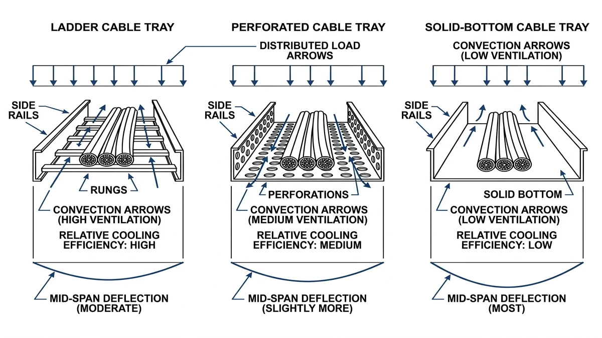
Thermal Management and Ampacity
Ampacity derating becomes critical when cables occupy more than about 50–60 % of tray width or run in hot environments, as the tray’s openness adds thermal resistance around heated cables. Ladder trays with 100–200 mm rung spacing provide the best convection and lowest derating, perforated trays typically need about 5–15 % derating under dense bundles, and solid-bottom trays—especially with covers—can require 20–30 % derating, guided by IEC 60364 or local ampacity rules.
Environment, Containment, and Cable Type
Environmental exposure determines how enclosed the tray should be: dirty or corrosive areas often use perforated or solid trays with covers for instrumentation and fiber, with materials selected to match corrosion categories such as ISO 12944 . EMI-sensitive circuits benefit from solid or closely perforated steel trays that provide partial shielding when bonded, and in fire-prone routes, more closed trays can limit direct flame and hot gas flow when combined with fire-resistant cables and firestopping, while open ladders remain preferred for heavy power where inspection and venting are critical.
[Expert Insight]
– Converting long solid-tray sections near MCCs back to ladder in brownfield upgrades has recovered 5–10 K of thermal margin on existing cables, avoiding upsizing.
– Maintenance teams report fewer overheating hotspots where high-load feeders remain on open ladders and are segregated from dense control bundles.
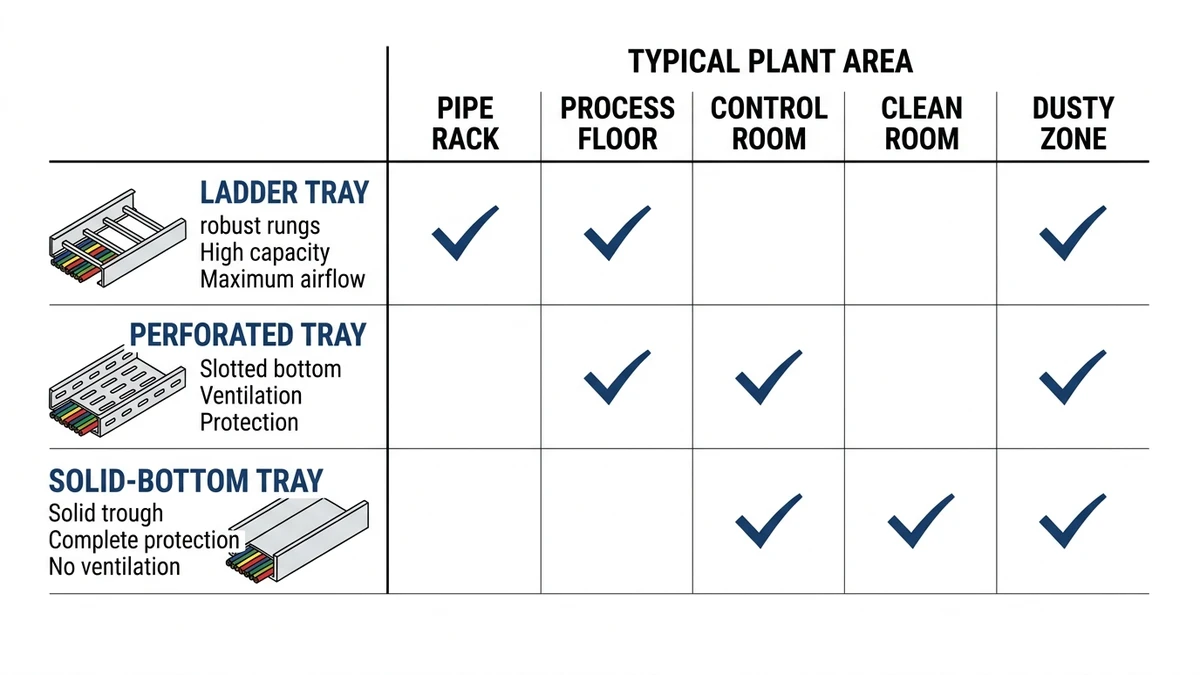
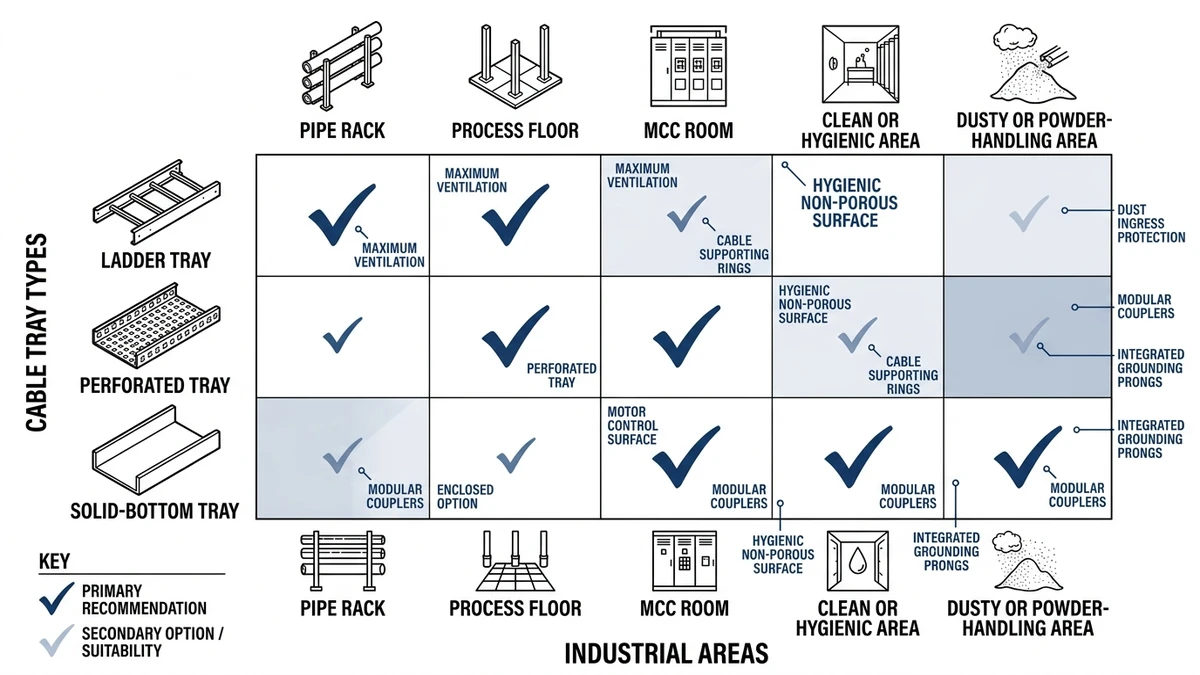
Industrial Use Cases for Ladder, Perforated, and Solid Trays by Area
Cable tray performance varies with temperature, contamination, fire risk, and access, so the same tray behaves differently in a hot pipe rack, a washdown room, or an MCC. Matching tray type to area conditions improves reliability and simplifies maintenance.
Outdoor Pipe Racks and Main Power Routes
For long outdoor runs and main feeders (typically 400–1 000 mm wide, 3–6 kV or LV >150 mm²), ladder trays are standard because open rungs provide drainage and airflow, keeping derating modest at 40–50 °C ambient while carrying >100 kg/m over spans up to about 6 m. Covers are added locally for UV, ice, or falling-object protection at the cost of extra dead load, whereas perforated and solid trays outdoors are generally reserved for lighter control and instrumentation circuits and need more attention to debris accumulation.
Indoor MCC, Switchgear, and Electrical Rooms
In clean, air-conditioned rooms (≈20–35 °C), ladder trays carry heavy LV power and motor feeders, ease future additions, and allow direct thermal and visual checks. Perforated trays support dense control and signal cables needing continuous support and flexible routing, while solid trays are limited to short sections—such as under raised floors or above sensitive equipment—where drip protection or extra shielding is required.
Process Areas with Dust, Drips, or Chemicals
In production areas, contamination and washdown patterns shape tray choice: ladder trays above equipment shed dust and liquids and allow fast inspection but leave cables exposed. Perforated trays better support smaller mixed cables yet can retain fine powders, whereas solid-bottom trays with covers are favored directly above sensitive equipment or in corrosive spray zones, accepting greater derating and typically shortening spans (for example, from about 3 m to 2 m) to control deflection and contamination load.
Hazardous Areas and Fire-Risk Zones
In Zone 1/2 or Class I, Div. 1/2 hydrocarbon areas and fire-risk corridors, ladder trays are preferred for power where fireproofing and venting are needed, while solid or perforated trays with metallic covers carry instruments and communications needing mechanical and thermal shielding. Here, fire load, fault containment, and evacuation routes dominate, so designers balance flame spread and protection, often using open ladders with fireproofed power circuits and fully enclosed solid runs for critical shutdown or communication cables.
[Expert Insight]
– In fire-risk corridors, power cables on ladder with targeted fireproofing and critical control on solid-bottom covered steel trays have shown better post-event survivability.
– Gas plant operators note faster root-cause analysis when major power routes remain visible on ladders and only selected control runs are fully enclosed.
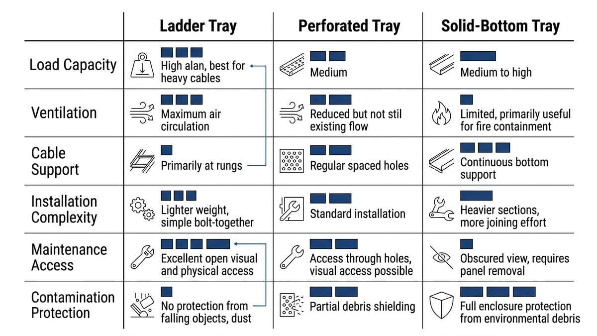
Comparing Ladder, Perforated, and Solid Trays for Industrial Design Trade-Offs
Key tray trade-offs involve load capacity, thermal performance, environmental protection, and maintainability across 2–6 m spans and various contamination or corrosion conditions. Using “favor / avoid / check before specifying” rules is more robust than defaulting to one tray type.
Comparison Matrix of Field-Relevant Trade-Offs
Parameter / Field Condition
Ladder Cable Tray – Advantages
Ladder Cable Tray – Limitations
Perforated Tray – Advantages
Perforated Tray – Limitations
Solid-Bottom Tray – Advantages
Solid-Bottom Tray – Limitations
Thermal performance & ampacity
Maximum ventilation; often 0–10 % ampacity derating for 50–200 mm² power cables
Poor for very small or unsupported cables; not ideal for EMC-sensitive runs
Better cooling than solid; typical 10–20 % derating
Hot spots under dense bundles; must check IEC 61537 guidance
Highest protection; suitable for sensitive control/instrumentation
Worst cooling; derating can exceed 20–30 % in hot (>40 °C) environments
Load capacity & span
High load class; 300–600 mm width spanning ~3 m with ≤L/200 deflection
Large cables can “saddle” on rungs if spacing >300 mm
Good for mixed light–medium duty cable loads
Heavier than ladder for same span; may need 2–2.5 m max span
Stiff base supports small-diameter cables well
Highest self-weight; often limited to ≤2 m spans for heavy loads
Contamination (dust, liquids, debris)
Open design sheds dust and liquids easily
Poor against falling debris, dripping chemicals, or oil mist
Reduces fall-through; perforations drain some liquids
Vulnerable to fine dust and splashing liquids
Best barrier for dust, oil, and small debris
Traps contamination; needs drainage and cleaning access
Outdoor & corrosive environments
Easy to hot-dip galvanize; good drainage and drying
Wind uplift and solar exposure can be higher
Similar corrosion treatment; slightly more surface to corrode
Perforation edges can initiate corrosion
Shields cables from UV and direct spray
Water pooling and under-film corrosion if not detailed carefully
Cable support & small-diameter cables
Excellent for large power cables ≥50 mm diameter
Poor continuous support for ∅<10 mm control/fiber cables
Better continuous support with perforations as intermediate
May still need extras for very small or delicate cables
Continuous support; good for fiber, instrumentation, small control
Higher risk of heat build-up and over-tight clamping in dense bundles
Inspection, modification, maintenance
Fast visual inspection; easy to add or relocate circuits
Minimal physical protection; may need more frequent checks
Balanced; reasonable access and protection
Perforations can partially obscure small defects
Maximum physical protection, useful for critical circuits
Slower access; covers or sections must be opened for each modification
EMC / signal integrity
Most open; minimal shielding
Poor for noisy or sensitive low-level signals
Some attenuation with metal web
Not equivalent to a shielded duct
Best inherent shielding, especially with cover
Still may require screened cables and proper bonding
Fire behavior & smoke spread
Venting can limit heat build-up; easier sprinkler reach
Openings can allow flame spread along cable route
Some barrier effect vs. ladder
Perforations still pass hot gases and smoke
Strong barrier to hot gases and flame spread
Can channel smoke; needs firestopping at penetrations
Cost & installation speed
Generally low cost per meter and fast to install
Needs more cleats or ties on vertical runs
Mid-range cost; good compromise for mixed systems
More cutting and deburring during modification
Highest material and labor cost
Heavier handling; more complex supports and fittings
Favor Ladder, Perforated, or Solid When…
As a quick selection guide:
Favor ladder trays when spans are 3–6 m, cable loads are ≥50 kg/m, and thermal margin is tight (e.g., 90 °C cables in 35–45 °C ambient).
Avoid ladder where EMC shielding or full physical protection is a primary requirement.
Check rung spacing, support span, and load class against the heaviest bundle and short-circuit forces.
Favor perforated trays for mixed power and control routes with moderate loads (20–60 kg/m) where some protection is needed but cooling remains important.
Avoid perforated trays where heavy contamination or continuous washdown will clog perforations.
Check derating and spans for both cable size and expected contamination load.
Favor solid-bottom trays for low-level signal, instrument, and network cables in dirty, oily, or EMC-sensitive zones.
Avoid long, heavily loaded solid runs for high-current circuits without recalculating ampacity.
Check reduced support spans, drainage or cleaning access, and bonding continuity.
How Xinma Helps Coordinate Tray Type, Loading, and Support Details in Real Projects
On real projects, Xinma often sees ladders specified for 150–200 kg/m power loads but supported at 3.0 m where the datasheet assumed 2.0 m, perforated trays selected at 800 mm width without checking deflection, and solid trays used under dense fills without revisiting derating. These decisions change allowable span, maximum cable mass per meter, the need for covers and bracing, and thermal margin relative to IEC 60364 / NEC guidance .
Xinma’s role is to align the cable schedule, route drawings, and tray systems by confirming that ladder, perforated, or solid trays meet required load classes at the shown spans, ensuring fittings and supports match straight-run ratings, coordinating covers with added dead load and wind uplift, and detailing splice positions, midspan supports, earthing jumpers, and expansion joints. In heavy industrial projects, involving the tray manufacturer before IFC often reduces site rework by resolving misaligned supports, undersized fittings, and missing expansion joints during design instead of during shutdowns.
For standard references on mechanical performance, see IEC 61537 via the IEC webstore: IEC 61537 publication page.
Frequently Asked Questions
How do I decide between ladder and perforated cable trays for an MCC room?
Use ladder trays when the MCC feeds large motors or dense power circuits where heat dissipation and future additions matter, and perforated trays when most circuits are control, I/O, and communication with lower currents but high cable counts that benefit from continuous support.
When should I specify solid-bottom cable trays in an industrial plant?
Solid-bottom trays are most appropriate for short, critical segments carrying low-level signals, instrumentation, or network cables through dirty, oily, or high-EMI areas, especially where even small debris or washdown water must be kept away from the cable jacket.
How does support span influence the choice of cable tray type?
Longer support spans favor ladder trays because their open structural profiles carry higher loads with acceptable deflection, while perforated and solid trays typically require shorter spans to control sag once self-weight, cable mass, and any retained contamination are included.
Can I mix ladder, perforated, and solid trays on the same cable route?
Mixing tray types along a route is common, but every transition should be checked for load rating, support spacing, bonding continuity, and ampacity implications, particularly where high-current circuits move from ventilated ladder sections into more enclosed perforated or solid sections.
How does cable tray selection affect electromagnetic interference on control cables?
Open ladder trays offer minimal shielding, so sensitive control or communication cables running parallel to high-current feeders may experience more induced noise, whereas perforated or solid steel trays provide some attenuation that can reduce coupling when combined with proper bonding and cable segregation.
Kevin Zheng
Kevin Zheng is a manager linked to Shanghai Xinma Busway & Cable Tray Co., Ltd. He writes technical content on cable tray systems, installation practice, sizing logic, load classes, and related standards for industrial and infrastructure applications.