Perforated cable trays are the default cable management choice for industrial and commercial installations where ventilation, weight savings, and routing flexibility all matter simultaneously. But sourcing the right product from the right supplier is where most procurement teams either save money or create problems they’ll spend months fixing.
This guide is built around one question: how do you evaluate a perforated cable tray supplier before you’re locked into a contract?
What Are Perforated Cable Trays and Why Do They Matter for Your Project
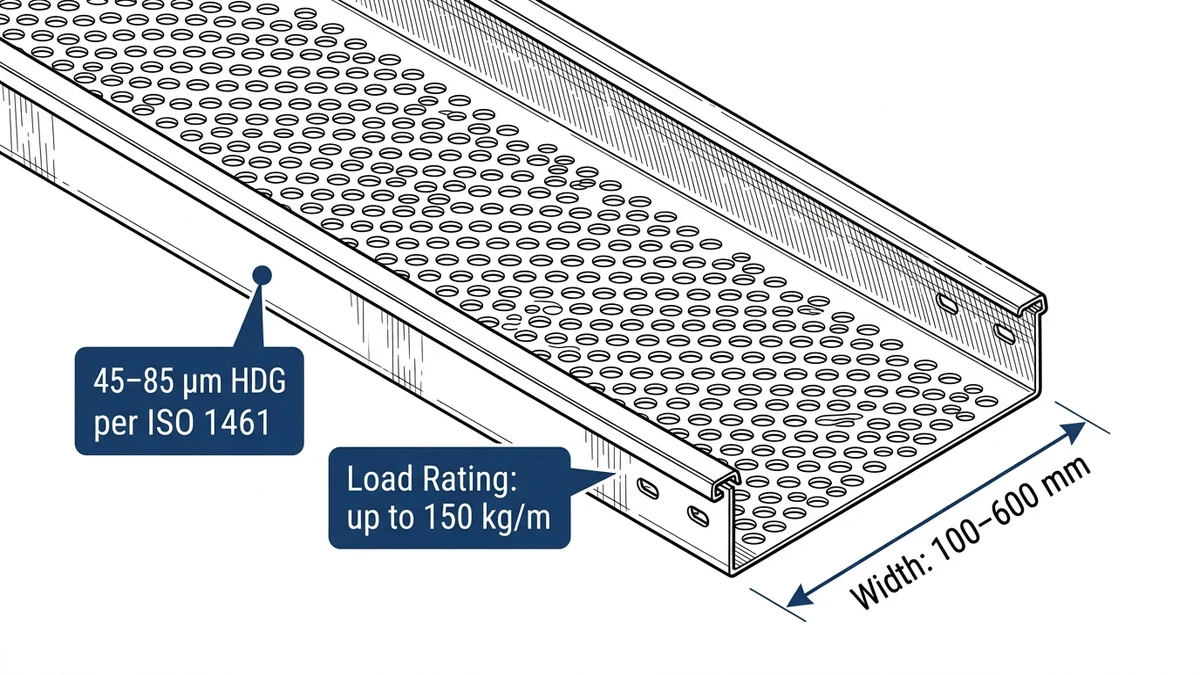
A perforated cable tray is a solid-bottom tray with punched openings — typically 30–50% open area — that allow airflow around cables, reduce tray weight by up to 20% compared to solid-bottom trays, and simplify cable tie-down without additional hardware. The perforations also allow water drainage in outdoor or wet-area installations, which is why they’re common in food processing plants, wastewater facilities, and commercial HVAC mechanical rooms.
For buyers evaluating perforated cable tray options, two parameters define baseline suitability before anything else: load capacity and material finish. Getting these right before comparing supplier pricing prevents costly substitutions mid-project.
How Perforated Trays Differ from Other Cable Routing Systems
Unlike cable ladders, which use open rungs and suit heavy power cables over long spans, perforated trays support smaller-diameter cables and mixed signal/power bundles where a continuous bottom surface prevents cable sag. Compared to solid-bottom trays, the perforated variant reduces material cost and improves thermal performance — relevant when cables are derated under IEC 60364-5-52, which governs current-carrying capacity based on installation method and grouping.
In a 2023 commercial office tower project in Guangzhou (18 floors, approximately 4,200 m of cable routing), switching from solid-bottom to perforated steel trays reduced total tray weight by roughly 1.8 tonnes, cutting structural support costs and installation labor by around 12%.
Key Parameters Buyers Should Anchor On
Load capacity: trays must meet the project’s distributed load class under IEC 61537, which classifies systems from Class A (50 kg/m) through Class D (200 kg/m) based on proof load deflection limits
Material and finish: standard options are pre-galvanized steel (Z275 coating per EN 10346), hot-dip galvanized after fabrication, or stainless steel (304 or 316L) for corrosive environments
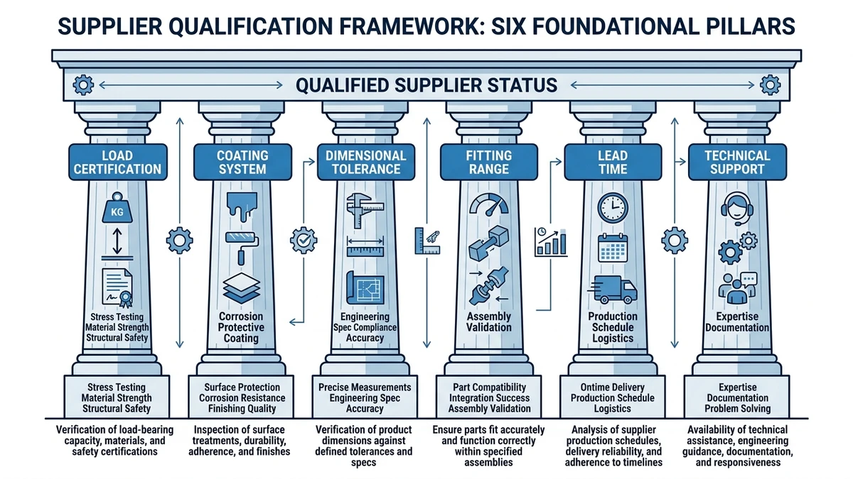
Figure 1. Six-pillar supplier qualification framework for perforated cable tray procurement: load certification, coating system, dimensional tolerance, fitting range, lead time reliability, and technical support.
[Expert Insight]
– Perforated trays with 30–40% open area provide meaningful airflow benefit, but the gain diminishes above 45% — at that point, structural rigidity starts to drop faster than thermal performance improves.
– In mixed signal/power routing, a continuous perforated bottom reduces EMI coupling risk compared to ladder trays, particularly for cables below 35 mm² cross-section.
– Specifying tray depth early matters: a 50 mm-deep tray limits future cable additions, while 100 mm depth gives room for phased expansion without re-routing.
– Always confirm that the perforation pattern is consistent across the full tray length — inconsistent punching from low-quality tooling creates stress concentration points under dynamic load.
Material and Finish Options That Affect Long-Term Performance
The wrong finish in a corrosive or high-humidity setting can lead to tray failure within 2–3 years. The right one can extend service life beyond 20 years. This is where supplier evaluation gets specific.
Hot-Dip Galvanized Steel
Hot-dip galvanized (HDG) steel is the most common choice for industrial cable management systems. The zinc coating thickness typically ranges from 45–85 µm per ISO 1461, providing solid protection against oxidation in outdoor and moderately corrosive environments. In a 2023 petrochemical plant expansion in Shandong Province (12,000 m of cable routing across process areas rated C3 per ISO 12944), HDG perforated trays recorded zero corrosion failures after 18 months of operation. Switching from pre-galvanized to HDG on that project extended the projected maintenance interval from 5 years to 15+ years, reducing lifecycle cost by roughly 40%.
Pre-Galvanized Steel
Pre-galvanized steel carries a thinner zinc layer, typically 7–20 µm, making it suitable for indoor commercial installations where moisture exposure is limited. It costs roughly 15–20% less than HDG but should not be used in environments with relative humidity consistently above 85% or where chemical vapors are present.
Stainless Steel (304 and 316)
For food processing, pharmaceutical, and coastal installations, stainless steel trays eliminate corrosion risk entirely. Grade 316 contains molybdenum, which raises chloride resistance — critical within 1 km of marine environments. The trade-off is cost: 316 stainless trays typically run 3–4× the price of HDG equivalents per linear meter.
Powder-Coated and PVC-Coated Options
Powder coating adds an aesthetic finish and mild corrosion resistance for commercial interiors, but it is not a substitute for galvanizing in industrial settings. PVC-coated trays are used in chemical environments where zinc would be attacked by acidic or alkaline vapors — the PVC layer typically measures 0.5–1.0 mm thick and must comply with.
When evaluating suppliers, request material test certificates (MTCs) confirming zinc coating weight in g/m² or coating thickness in µm. A generic “galvanized” label on a datasheet is not documentation.
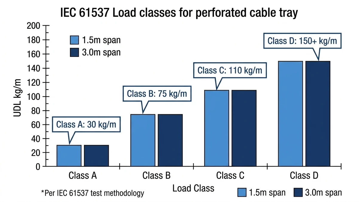
Figure 2. IEC 61537 load class comparison for perforated cable tray systems showing uniformly distributed load (UDL) ratings across Classes A–D at standard test spans of 1.5 m and 3.0 m.
[Expert Insight]
– ISO 1461 specifies minimum zinc coating by steel thickness category — for sections 1–3 mm thick, the minimum is 45 µm; for sections above 6 mm, it rises to 70 µm. Confirm which category your tray steel falls into before accepting a supplier’s coating claim.
– In coastal projects, the difference between 304 and 316 stainless is not marginal — 316 grade resists pitting corrosion from chloride ions that will visibly attack 304 within 12–18 months in high-exposure zones.
– Powder coating over bare steel (without a zinc primer) typically fails at cut edges within 3–5 years in humid environments. Ask suppliers whether their powder-coated trays use a zinc phosphate pre-treatment.
What to Look for in a Perforated Cable Tray Supplier
Choosing the right supplier directly affects installation cost, long-term reliability, and code compliance. The evaluation comes down to material quality, load certification, finish durability, and the supplier’s ability to deliver consistent product across project phases.
Material and Load Certification
Suppliers should provide third-party test reports confirming their load class — ranging from Class A (50 kg/m) to Class D (200 kg/m) under IEC 61537 — not just self-declared specifications. IEC 61537 also sets maximum allowable midspan deflection at L/200 under proof load. When a supplier claims compliance, ask for the specific load class and test span: a 3 m span at Class B (100 kg/m) is a very different product from one tested at 1.5 m.
In a 2023 petrochemical plant expansion in Shandong Province, the project team disqualified two suppliers early in procurement because neither could produce IEC 61537-compliant deflection test data for their 150 mm wide trays at a 1.5 m span. Switching to a certified supplier kept the cable management system on schedule and eliminated re-inspection risk — at a cost premium of only 4% on materials.
For a deeper look at how load class interacts with tray sizing decisions, the cable tray size calculation guide covers span-to-load relationships in detail.
Production Capacity and Lead Time
For projects requiring more than 5,000 m of tray, production capacity becomes a procurement risk. Confirm the supplier’s monthly output and whether standard widths (100 mm, 150 mm, 200 mm, 300 mm, 400 mm, 600 mm) are held in stock versus made-to-order. Lead times beyond 6 weeks for standard configurations typically signal limited manufacturing scale or over-reliance on subcontractors.
Technical Support and Documentation
Reliable suppliers provide installation drawings, span tables, and fitting catalogs — not just product datasheets. The ability to supply project-specific cut lists, custom lengths, or non-standard perforation patterns without minimum order penalties is a practical differentiator on complex routing layouts. Suppliers who manufacture under a documented quality management system (ISO 9001 or equivalent) provide more traceable product data, which matters during commissioning audits.
Availability of matching cable tray fittings — bends, tees, reducers, and splice plates — from the same production line is also worth confirming. Dimensional mismatches between tray body and fittings sourced from different manufacturers are a common on-site problem that’s entirely avoidable.
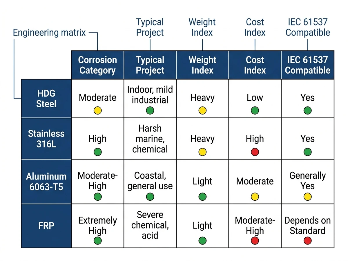
Figure 3. Material selection matrix for perforated cable tray systems mapping four material options — HDG steel, stainless steel 316L, aluminum alloy, and FRP — against corrosion category, project type, weight index, and relative cost.
Installation Considerations for Perforated Cable Trays
Selecting the right supplier is only half the equation. Proper installation determines whether the system performs to its rated load class over its full service life.
In a 2023 pharmaceutical plant expansion in Suzhou (12,000 m² production floor), incorrect support spacing caused midspan deflection exceeding 18 mm on 500 mm-wide trays under a 60 kg/m cable load, triggering a full rework that added three weeks to the schedule. The tray product was correctly specified — the installation wasn’t.
Support Spacing and Deflection Limits
IEC 61537 defines deflection limits as L/100 under working load, where L is the span between supports. For steel perforated trays, support spans typically range from 1.5 m to 3 m depending on load class and tray width. A 300 mm-wide tray rated at Class B (100 kg/m) generally requires supports at no more than 2 m intervals to stay within deflection limits. Exceeding that spacing — even by 200 mm — can push deflection into non-compliant territory under full cable fill.
For guidance on support system selection and spacing calculations, the cable tray support reference covers span tables and anchor configurations across common tray widths.
Cable Fill Ratio and Thermal Derating
The open perforation area (typically 30–40% of tray base area) promotes airflow, but fill ratio still governs ampacity derating. When cables occupy more than 40% of the tray’s cross-sectional area, thermal derating factors from apply, reducing allowable current per conductor. A 150 mm-wide tray is rarely sufficient for power cable bundles exceeding 8–10 cables of 35 mm² cross-section — calculate fill ratio before finalizing tray width.
Grounding Continuity
Perforated trays used as part of an equipment grounding path must maintain electrical continuity across all splice joints. NEMA VE 1 specifies bonding requirements for metallic cable tray systems, including minimum cross-sectional area for the grounding conductor where the tray itself serves as the ground return. Stainless steel and hot-dip galvanized trays generally maintain continuity well, but powder-coated trays require bonding jumpers at each joint to ensure a reliable ground path.
Certifications and Standards Every Buyer Should Verify
Certifications are the fastest way to separate reliable suppliers from risky ones. A tray that lacks third-party verification may pass visual inspection but fail under real load conditions.
IEC 61537 Load Classification
IEC 61537 is the primary international standard governing cable tray and cable ladder systems. It defines load classes from Class A (50 kg/m) through Class D (200 kg/m) and sets maximum allowable midspan deflection at L/200 under proof load. For most commercial HVAC and electrical distribution projects, Class B (100 kg/m) at a 3 m span is the baseline. Industrial plants with dense power cable bundles often require Class C or D.
In a 2023 pharmaceutical plant expansion in Suzhou, the procurement team required IEC 61537 Class C certification across all perforated trays. Suppliers who couldn’t produce third-party test reports were eliminated early, cutting qualification time by roughly 40% and avoiding two vendors whose in-house test data later proved inconsistent with independent lab results.
Corrosion Protection Standards
For outdoor or chemically aggressive environments, surface treatment certification matters as much as structural rating. Hot-dip galvanized trays should meet ISO 1461, which specifies a minimum zinc coating thickness of 45 µm on steel sections above 6 mm thick. Stainless steel trays used in food processing or coastal installations are typically specified to AISI 316L, which offers measurably better chloride resistance than 304-grade material.
UL and NEMA Compliance for North American Projects
Projects destined for the US or Canadian market should look for NEMA VE 1 compliance, which covers metal cable tray systems and defines dimensional tolerances, material grades, and load testing methodology. UL 870 covers wireways and auxiliary gutters.
What to Request from Suppliers
Third-party test reports (not just self-declared compliance)
Material mill certificates for steel or stainless steel grade
Coating thickness test records (zinc layer in µm or g/m²)
Load class and tested span documentation per IEC 61537
Suppliers who produce these documents without hesitation are generally the ones worth shortlisting.
Red Flags to Watch for When Evaluating Suppliers
Knowing what to look for is useful. Knowing what to walk away from is more useful.
No Third-Party Test Certification
If a supplier can only offer in-house test data with no third-party verification, that’s a serious problem. In the Shandong petrochemical project referenced earlier, two local suppliers were rejected after their “Class C” rated trays had never been independently tested. Substituting a certified supplier added only 4% to material costs but eliminated re-inspection risk entirely.
Vague Material Specifications
A supplier who cannot specify the base metal grade, coating weight in g/m², or corrosion resistance class is likely sourcing inconsistently. Ask for mill certificates and coating test reports — legitimate manufacturers provide these as standard documentation.
Missing Accessories Compatibility Data
Perforated cable trays require fittings that must be dimensionally and structurally compatible with the tray body. A supplier without a documented accessories catalog, or one who sources fittings from a different manufacturer without compatibility testing, creates installation problems that only surface on-site. Reviewing the full range of cable tray accessories before finalizing a supplier helps confirm system-level compatibility.
No Minimum Order Flexibility or Lead Time Transparency
Industrial and commercial projects often require mixed quantities across multiple tray widths (typically 100 mm to 600 mm) and depths (50 mm to 150 mm). Suppliers who enforce rigid minimum order quantities without project-based flexibility, or who cannot commit to lead times in writing, introduce scheduling risk that compounds during phased construction.
Unverifiable Factory Audit History
Reputable suppliers maintain ISO 9001 quality management certification and can provide recent audit records. If a supplier deflects audit requests or cannot produce documentation within 48 hours, that gap in transparency is itself a qualification failure.
Supplier Evaluation Checklist
Before finalizing any supplier, confirm:
Material traceability: Q235B or equivalent steel with mill certificates
Coating documentation: zinc layer thickness per ISO 1461 or equivalent
Load test reports: independent lab results aligned with IEC 61537
Custom fabrication capability: non-standard widths (e.g., 150 mm, 900 mm) and lengths without minimum order penalties
Lead time and stock availability for your project schedule
Matching fittings from the same production line
ISO 9001 certification with recent audit records
Prioritize suppliers who offer full documentation packages and can support site-specific engineering queries. A supplier’s willingness to provide technical support before the sale is a reliable indicator of how they’ll perform after it. The cable tray installation guide is a useful reference for confirming that a supplier’s documentation aligns with real installation requirements.
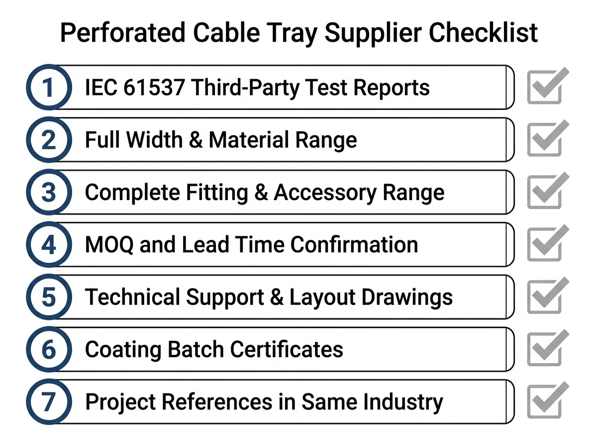
Figure 4. Seven-point supplier qualification checklist for perforated cable tray procurement, covering IEC 61537 test documentation, fitting range completeness, MOQ thresholds, and project reference verification.
This article has been updated with explicit source and procurement checks so engineering, EPC, and purchasing teams can verify the recommendations instead of relying only on generic product descriptions. For project use, treat the table below as a starting evidence map and confirm the final requirements against local codes, consultant drawings, and supplier submittals.
Use this source to verify standards, product scope, installation assumptions, or supplier evidence before final specification.
Buyer Verification Checklist
Request drawings that show tray width, depth, side rail profile, bend radius, fittings, and support spacing.
Ask for load tables or engineering assumptions that state test span, load class, and deflection criteria.
Confirm material grade, surface finish, coating method, and corrosion exposure assumptions before comparing prices.
Check whether accessories such as covers, couplers, reducers, clamps, grounding jumpers, and brackets are included.
For EPC or export orders, review packaging, labeling, inspection records, and drawing revision control before shipment.
Frequently Asked Questions
How do I verify that a perforated cable tray supplier is IEC 61537 compliant?
Request third-party test reports — not just spec sheets — that confirm the tray’s load class (Class A through D) and the tested span, typically 1.5 m or 3 m. Self-declared compliance without independent lab data is not sufficient for most industrial procurement audits.
What zinc coating thickness should I specify for outdoor perforated cable trays?
Hot-dip galvanized trays for outdoor use should generally meet ISO 1461, with zinc coating thickness of at least 45 µm for thinner steel sections and up to 85 µm for heavier sections — the exact minimum depends on the steel thickness category defined in the standard.
When should I choose 316 stainless steel over hot-dip galvanized for cable trays?
316 stainless steel is typically specified for installations within approximately 1 km of marine environments, in food processing or pharmaceutical facilities, or where chloride exposure is a known factor — environments where zinc coatings degrade faster than the project’s maintenance cycle can accommodate.
What fill ratio should I use when sizing a perforated cable tray?
A 40% fill ratio is a common starting point for initial cable tray sizing, leaving headroom for future cable additions and maintaining adequate airflow for thermal management. Exceeding 40% fill typically triggers ampacity derating calculations under the applicable wiring standard.
How do I confirm that a supplier’s fittings are compatible with their tray product?
Ask for a documented accessories catalog that lists dimensional tolerances for bends, tees, reducers, and splice plates relative to the tray body. Fittings sourced from a different manufacturer without compatibility testing are a frequent source of on-site installation problems.
What lead time is reasonable for standard perforated cable tray widths?
For standard widths (150 mm, 300 mm, 450 mm, 600 mm) held in stock, 2–4 weeks is a reasonable expectation from an established manufacturer. Lead times beyond 6 weeks for standard configurations often indicate limited production capacity or reliance on subcontractors.
Does a perforated cable tray need bonding jumpers at splice joints?
For trays used as part of an equipment grounding path, bonding requirements depend on the tray finish. Hot-dip galvanized and stainless steel trays generally maintain electrical continuity across joints, while powder-coated or painted trays typically require bonding jumpers at each splice to ensure a reliable ground return path.
Kevin Zheng
Kevin Zheng is a manager linked to Shanghai Xinma Busway & Cable Tray Co., Ltd. He writes technical content on cable tray systems, installation practice, sizing logic, load classes, and related standards for industrial and infrastructure applications.