Perforated Cable Tray Applications Across Industrial and Commercial Projects
Perforated cable trays are among the most versatile cable management systems in use today, suited to environments ranging from commercial office builds to heavy industrial plants. The solid base with punched openings — typically 30–50% open area — provides continuous cable support while allowing airflow, drainage, and visual inspection without removing cables from the tray. That combination of structural support and openness is what makes the perforated format the default choice across so many project types.
Understanding field conditions upfront determines whether a perforated tray is the right cable routing solution or whether a ladder cable tray or solid-bottom variant better fits the application.
Where Perforated Cable Trays Are Used: Key Application Environments
Perforated cable tray applications span industrial and commercial environments where controlled cable routing, ventilation, and cost efficiency are all required simultaneously. The perforated base — typically 30–50% open area — allows heat dissipation from power cables while keeping smaller instrumentation and data cables organized within a single cable management system. For most mixed-cable routing scenarios, it’s the first format engineers reach for.
Commercial Buildings and Office Fit-Outs
In commercial construction, perforated cable trays are the standard choice for above-ceiling cable routing in HVAC-accessible plenum spaces. A 2023 fit-out of a 12-floor office tower in Guangzhou used 150 mm wide perforated steel trays throughout raised floor and ceiling void zones, reducing installation labor by approximately 22% compared to conduit runs — primarily because tray systems allow multiple cables to be laid simultaneously without individual conduit pulls.
Routing flexibility drives that efficiency. Perforated trays accept 90° bends, tees, and reducers without field fabrication. On a mid-size commercial floor plate of 2,000–3,000 m², a zone might require 8–12 tray direction changes; prefabricated fittings cut installation time per change from roughly 45 minutes (conduit) to under 15 minutes.
For low-voltage data and communications cabling, tray widths of 100–300 mm are typical, with load capacities in the 15–30 kg/m range. Cable fill ratios are kept below 40% of cross-sectional area to maintain ampacity derating margins and satisfy applicable wiring regulations for enclosed spaces.
Industrial Facilities and Process Plants
In petrochemical plants, food processing facilities, and manufacturing environments, perforated cable trays handle both power distribution and instrument signal cables. The open base supports natural convection cooling — critical when cables carry sustained loads near their rated ampacity.
IEC 61537 governs cable tray system performance and specifies deflection limits. A 500 mm wide tray spanning 3 m must not exceed L/200 midspan deflection under proof load, which translates to a maximum of 15 mm for that span. Stainless steel or hot-dip galvanized perforated trays are selected in corrosive environments, where salt spray or chemical exposure would degrade standard pre-galvanized finishes within 2–5 years.
Data Centers and Server Rooms
Perforated trays are widely deployed in data center underfloor and overhead cable routing zones. The open area supports airflow management strategies aligned with hot-aisle/cold-aisle containment layouts. Tray fill ratios are kept below 40% of cross-sectional area to maintain cable accessibility and thermal performance — consistent with NEMA VE 1 guidance on cable tray fill. For a deeper look at how these systems are deployed across building types, see how cable tray systems are used.
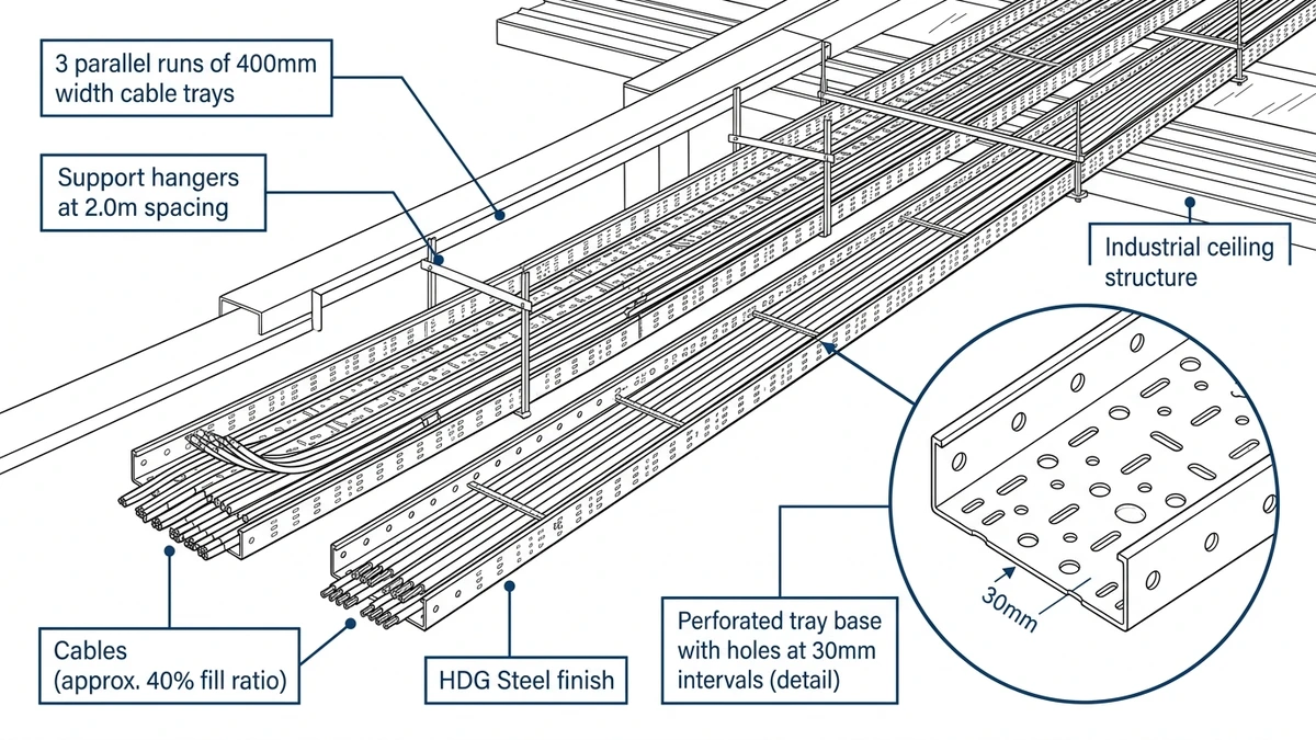
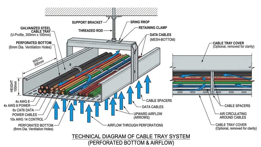
Figure 1. Cross-sectional detail of perforated cable tray showing 25–50 mm perforation intervals, base plate, sidewall return flange, and convective airflow path through perforations under loaded conditions.
[Expert Insight]
– In data center overhead routing, perforated trays with ≥ 35% open area measurably reduce cable bundle temperatures compared to solid-bottom trays under equivalent fill conditions — a factor that affects both ampacity and long-term insulation life.
– NEMA VE 1 recommends a 40% fill ratio as the practical ceiling for initial installation, leaving headroom for future cable additions without a full tray redesign.
– Segregating power and fiber runs into separate tray sections — even within the same overhead zone — reduces troubleshooting time during fault-finding and simplifies future upgrades.
– Hot-aisle/cold-aisle containment strategies depend on predictable airflow paths; tray fill discipline is as much an airflow management decision as a cable management one.
Industrial Facilities
Perforated cable tray applications in industrial facilities cover some of the most demanding routing conditions in any built environment. Manufacturing plants, petrochemical refineries, and heavy processing facilities share a common challenge: high cable density, aggressive ambient conditions, and the need for continuous airflow around power and control cables to prevent ampacity derating.
Power Distribution in Manufacturing Plants
In a motor control center (MCC) installation at a mid-scale automotive assembly plant in Guangzhou (2023), perforated steel cable trays rated at 150 kg/m load capacity routed 600 V power cables from MCCs to production line drives across a 120 m span. The perforation pattern — 30% open area — provided enough ventilation to maintain cable ampacity ratings without requiring derating factors beyond those already applied for ambient temperature. Cable fill was kept at 40% of tray cross-section, consistent with NEC 392.22 fill ratio guidelines, which helped maintenance crews identify and replace individual cables without disturbing adjacent runs.
Hazardous Area Routing
In petrochemical and oil refinery environments, perforated trays are typically specified in hot-dip galvanized or stainless steel to resist hydrogen sulfide and chloride exposure. Tray widths of 300–600 mm are common for instrument cable segregation, keeping signal cables physically separated from power runs by at least 200 mm — a spacing requirement referenced in IEC 61537 to reduce electromagnetic interference on low-voltage instrumentation circuits.
Ventilation and Thermal Management
The physics is straightforward: perforations allow convective airflow across cable jackets, directly affecting heat dissipation. In a steel mill auxiliary building in Hebei, engineers documented a 12°C reduction in cable surface temperature on perforated trays versus solid-bottom trays under identical load conditions. That thermal difference translates to measurable ampacity recovery — typically 5–8% depending on cable grouping — which can eliminate the need for oversized conductors in dense routing zones.
For facilities where cable routing intersects with process piping or structural steel, perforated trays also accept standard clamp-type cable cleats and tie-down hardware without modification, keeping installation straightforward even in congested overhead zones.
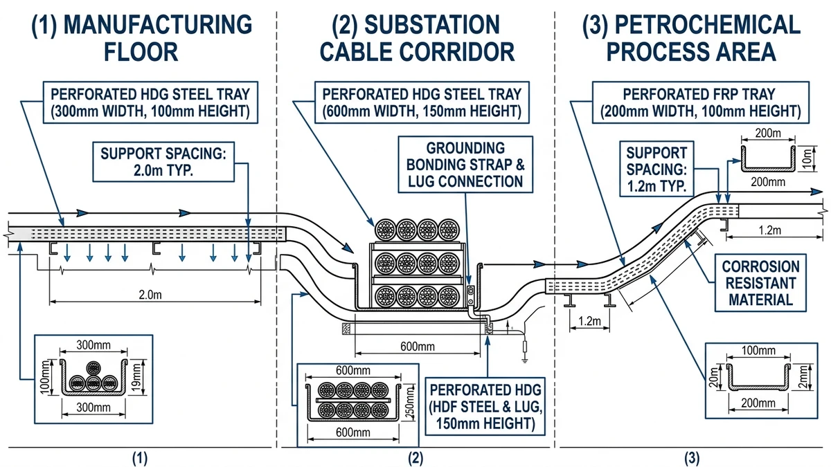
Figure 2. Schematic cross-section of an industrial facility showing perforated cable tray routing across three zones: manufacturing floor (HDG steel, 300mm), substation cable corridor (HDG steel, 600mm), and petrochemical process area (FRP, 200mm) with support spacing callouts.
[Expert Insight]
– The 12°C surface temperature reduction documented in the Hebei steel mill case is consistent with published convection modeling for perforated versus solid-bottom trays at 30–40% fill — not an outlier result.
– IEC 60364-5-52 provides correction factors for cables in ventilated versus enclosed trays; applying these correctly at the design stage often eliminates the need for conductor upsizing.
– In compressor rooms and press lines, vibration accelerates fastener loosening at tray splice joints — structural check intervals should be shortened to 18 months rather than the standard 36 months.
– Instrument cable segregation by 200 mm minimum spacing (per IEC 61537) is a practical EMC measure, but shielded cable may still be required in high-interference zones regardless of physical separation.
Commercial and Institutional Buildings
Perforated cable tray applications in commercial and institutional buildings shift priorities toward aesthetics, flexibility, and code compliance in occupied spaces. In a 2023 retrofit of a 12-story office tower in Guangzhou (approximately 45,000 m² total floor area), perforated steel trays reduced above-ceiling cable routing labor by 28% compared to the previous conduit-only approach, while maintaining the clean soffits required by tenant fit-out specifications.
Office and Mixed-Use Developments
In open-plan office environments, perforated cable trays typically run at 150–300 mm width in ceiling plenums, carrying low-voltage data, fire alarm, and lighting control cables in segregated compartments. The perforation pattern — usually 5 mm diameter holes at 20 mm centers — provides enough airflow to prevent heat buildup in densely packed horizontal runs, which matters when cable fill ratios approach the 40% threshold recommended under IEC 61537 for derating calculations.
The perforated base accepts cable ties at any point along the tray — no fixed tie-off positions as with ladder rungs — which is a practical advantage when cable routes change between tenant cycles.
Healthcare and Education Facilities
Hospitals and university buildings introduce stricter requirements around infection control and electromagnetic compatibility. Perforated trays in these environments are typically specified in 316L stainless steel or hot-dip galvanized carbon steel with a minimum coating thickness of 85 μm, both to resist cleaning agents and to meet requirements for surface hygiene.
In a university science building project in Chengdu (completed 2022, 18 laboratory suites), perforated trays separated IT backbone cabling from 230 V power feeds with a minimum 50 mm air gap between adjacent trays — a separation distance consistent with EMC guidance under IEC 61000-5-2 for cable routing in sensitive environments. This avoided shielded cable upgrades that would have added approximately 22% to the cabling material budget.
Institutional projects also benefit from the tray’s inspectability: maintenance teams can visually verify cable condition and identify unauthorized additions without removing covers, supporting ongoing compliance audits.
Perforated Cable Tray in Wet and Corrosive Environments
Perforated cable tray performs reliably in wet, chemically aggressive, and high-humidity environments — provided the material specification matches the exposure class. The perforated base allows water drainage and airflow simultaneously, preventing pooling and reducing corrosion initiation on cable jackets.
Material Selection by Exposure Class
In food processing plants and coastal facilities, hot-dip galvanized perforated trays (zinc coating ≥ 85 μm per ISO 1461) handle moderate corrosion loads. For harsher chemical exposure — chlorine atmospheres in water treatment plants or acid mist in battery rooms — 316L stainless steel trays are the standard choice, offering pitting resistance equivalent (PRE) values above 24, compared to 18 for 304 grade. Fiberglass reinforced plastic (FRP) trays are specified where both chemical resistance and electrical isolation are required, such as in electroplating facilities.
In a 2023 wastewater treatment plant expansion in Guangdong (12 pump stations, 4.2 km total cable routing), the project team switched from solid-bottom trays to hot-dip galvanized perforated trays. The change reduced standing water incidents across seasonal flooding cycles and cut cable jacket degradation complaints from maintenance staff to zero over the 18-month post-installation review.
Drainage and Ventilation Physics
Open area percentage directly governs drainage rate. A 150 mm wide perforated tray with 40% perforation ratio drains approximately 3× faster than a solid-bottom tray under equivalent rainfall ingress conditions. This matters in outdoor cable bridges and rooftop routing where standing water accelerates galvanic corrosion between dissimilar metals — cable armor, tray hardware, and support brackets.
Ventilation through the perforations also supports ampacity. IEC 60364-5-52 provides correction factors for cables installed in enclosed versus ventilated trays. In a perforated tray with ≥ 30% open area, cables can recover up to 10–15% of the ampacity derating applied to solid-bottom enclosed systems, depending on ambient temperature and fill ratio. The full standard is available through the IEC webstore.
Outdoor and Transitional Zones
Where cable routing transitions from indoor conditioned space to outdoor exposed runs, perforated trays with UV-stabilized FRP or powder-coated aluminum (coating thickness ≥ 60 μm) handle thermal cycling between -20°C and +60°C without delamination or coating failure. Expansion splice plates at intervals of 6–9 m accommodate linear thermal expansion — typically 1.2–2.4 mm per meter of aluminum tray across that temperature range.
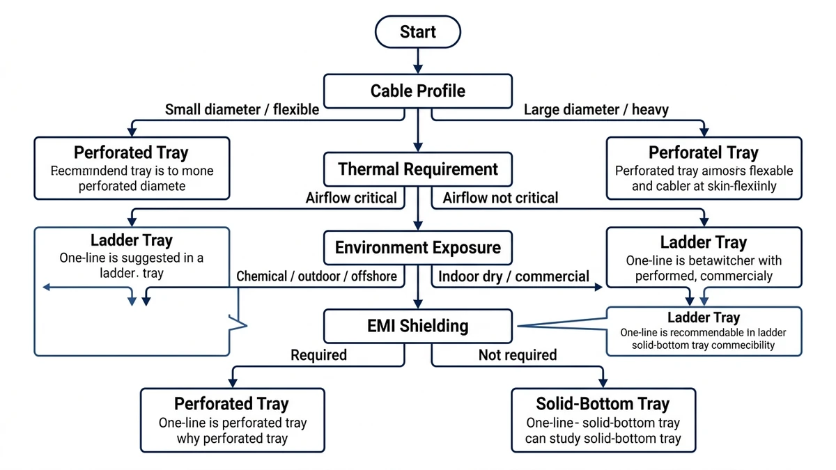
Figure 3. Engineering selection flowchart for cable tray format selection based on four decision criteria: cable diameter profile, thermal management requirement, environment exposure class, and EMI shielding need. Output nodes indicate recommended tray format per IEC 61537 application guidance.
Maintenance Access and Inspection in Perforated Cable Tray Systems
One advantage that compounds over a system’s service life is direct visual and physical access to cables without dismantling the cable management system. In a 2023 pharmaceutical plant expansion in Suzhou (approximately 4,200 m of cable tray installed), maintenance crews reduced fault-location time by 40% compared to the previous conduit-based layout, because technicians could trace cable runs and identify damaged insulation without pulling cables through enclosed conduit.
Visual Inspection Efficiency
The open top of a perforated tray allows infrared thermography scans to detect hotspots along cable runs during live operation — a technique increasingly required under IEC 60364-6 (verification of electrical installations). Thermographers can scan tray sections at walking pace, typically covering 50–80 m per hour, compared to 10–15 m per hour when working around solid-bottom enclosed systems. In facilities with maintenance windows of 4 hours or less, that difference is significant.
Cable Addition and Replacement
When load requirements change, perforated trays allow new cables to be laid in without disturbing existing runs. The perforated base makes it straightforward to secure additional cables with ties through the slots — standard 4.8 mm × 300 mm nylon ties fit most perforation patterns without tools. Adding cables to a fully enclosed wireway, by contrast, requires partial disassembly.
For replacement work, the open structure means a single damaged cable can be extracted laterally rather than pulled end-to-end through a conduit run. In a 2024 automotive assembly plant retrofit in Wuhan, this reduced average cable replacement time from 3.5 hours per run to under 45 minutes per run across a 600 V power distribution network.
Cleaning and Contamination Control
In food processing and cleanroom environments, perforated trays allow debris and condensation to fall through rather than accumulate. Maintenance teams can blow out dust or rinse tray sections without removing cables, provided the tray material is rated for the cleaning agents used. Routine inspection intervals in industrial settings are typically set at 12 months for visual checks and 36 months for load and fastener verification — though facilities operating under continuous vibration (compressor rooms, press lines) often shorten the structural check interval to 18 months.
Installation Considerations for Perforated Cable Trays in the Field
Perforated cable tray installation requires careful planning around support spacing, cable fill, and environmental exposure before a single bracket goes into the wall. Getting these parameters right at the design stage prevents costly rework and ensures the system performs within the limits set by IEC 61537 (cable management — cable tray systems and cable ladder systems). A practical reference for field teams is this cable tray installation guide, which covers support spacing, grounding, and fill ratio checks in sequence.
Support Spacing and Deflection
Support intervals directly control midspan deflection. For a 300 mm wide perforated steel tray spanning 1.5 m under a 75 kg/m distributed cable load, deflection typically falls between 5–8 mm — within the IEC 61537 Class B limit of L/200. Extending the span to 2.4 m without adjusting the load class pushes deflection beyond acceptable limits and risks permanent deformation.
In a 2023 pharmaceutical plant fit-out in Suzhou (approximately 8,400 m² of cable routing), the project team standardized on 1.5 m support centers for 200 mm perforated trays carrying instrumentation cables, achieving zero deflection failures across 14 months of post-installation inspection.
Cable Fill and Ampacity Derating
Perforated trays allow airflow through the base, which helps dissipate heat from loaded cables — but fill ratio still governs ampacity derating. NEC 392.22 and equivalent national standards generally limit single-layer fill to 50% of the tray’s usable cross-sectional area for power cables. Exceeding this threshold forces a derating factor on cable ampacity, typically reducing allowable current by 15–25% depending on cable grouping and ambient temperature.
Corrosion Protection Selection
Field environment determines finish. Hot-dip galvanized trays (coating thickness ≥ 85 μm per ISO 1461) suit outdoor and moderately corrosive industrial zones. Epoxy-coated or stainless steel variants are specified where chemical exposure or humidity exceeds the tolerance of standard zinc coatings. Matching the finish to the actual site classification — rather than defaulting to the cheapest option — is where most field errors originate.
Grounding Continuity
Perforated trays used as equipment grounding conductors must maintain electrical continuity across all splice joints. Bonding jumpers or listed splice plates with verified contact resistance below 0.1 Ω per joint are required where the tray serves a grounding function. Skipping this step is a common oversight during fast-track installations and creates compliance issues during final inspection. Properly specified cable tray accessories — including listed splice plates and bonding hardware — are the practical fix.
Sizing Perforated Cable Trays for Real-World Load Conditions
Selecting the right perforated cable tray size starts with two numbers: total cable fill weight in kg/m and tray span between supports. Get either wrong and you’re looking at excessive deflection, code violations, or a costly retrofit.
Fill Ratio and Cable Weight
IEC 61537 sets the framework for load classification, ranging from Class A at 50 kg/m up to Class D at 200 kg/m. In practice, perforated trays in commercial office buildings typically carry 20–60 kg/m of low-voltage data and power cables, landing in Class A or B territory. Industrial plants running heavier instrumentation and power cables can push 80–120 kg/m, requiring Class C trays with reinforced side rails.
Fill ratio — the percentage of tray cross-section occupied by cables — should stay at or below 40% for single-layer fills per NEMA VE 1 guidelines. Exceeding this threshold restricts airflow through the perforations, which defeats one of the primary thermal management advantages of the perforated design.
Span and Deflection Limits
A 300 mm wide perforated tray spanning 1.5 m under a 60 kg/m load typically deflects 4–6 mm — well within the IEC 61537 limit of L/200 (7.5 mm at that span). Extending the same tray to a 2.4 m span under identical load pushes deflection toward 15–18 mm, exceeding the allowable limit and requiring either a heavier load class tray or an additional support.
In a 2023 pharmaceutical manufacturing facility fit-out in Suzhou (approximately 18,000 m² of production floor), the engineering team standardized on 400 mm wide perforated trays at 1.5 m support intervals. This configuration kept deflection under 8 mm across all runs while maintaining the 40% fill ratio needed for cleanroom cable ampacity derating compliance. Zero tray replacements were recorded during the 14-month construction phase — a direct outcome of front-loading the sizing calculation.
Tray Width Selection
Width selection follows cable grouping logic. Route power and data cables in separate trays wherever possible; when combined runs are unavoidable, a 500 mm wide tray with a center divider keeps separation distances compliant with local wiring regulations. Standard widths of 100, 150, 200, 300, 400, and 500 mm cover the majority of commercial and light industrial applications, with 600 mm reserved for high-density cable routing zones like main distribution frames or motor control center feeders. For a full breakdown of width-to-load relationships, the cable tray size calculation guide walks through the method step by step.
Xinma’s perforated cable tray range covers the full width spectrum from 100 mm to 600 mm in pre-galvanized, hot-dip galvanized, and stainless steel finishes, with load classes matched to IEC 61537 requirements.
This article has been updated with explicit source and procurement checks so engineering, EPC, and purchasing teams can verify the recommendations instead of relying only on generic product descriptions. For project use, treat the table below as a starting evidence map and confirm the final requirements against local codes, consultant drawings, and supplier submittals.
Use this source to verify standards, product scope, installation assumptions, or supplier evidence before final specification.
Buyer Verification Checklist
Request drawings that show tray width, depth, side rail profile, bend radius, fittings, and support spacing.
Ask for load tables or engineering assumptions that state test span, load class, and deflection criteria.
Confirm material grade, surface finish, coating method, and corrosion exposure assumptions before comparing prices.
Check whether accessories such as covers, couplers, reducers, clamps, grounding jumpers, and brackets are included.
For EPC or export orders, review packaging, labeling, inspection records, and drawing revision control before shipment.
Frequently Asked Questions
What environments are perforated cable trays best suited for?
Perforated cable trays work well across a wide range of environments — from commercial ceiling plenums and data centers to industrial process plants and outdoor cable bridges — wherever a combination of cable support, airflow, and visual access is needed. The material finish (pre-galvanized, hot-dip galvanized, stainless steel, or FRP) determines suitability for corrosive or wet conditions.
How do I calculate the correct perforated cable tray size for my project?
Start with the total cable fill weight in kg/m and the planned span between supports, then match those values to an IEC 61537 load class. Keep fill ratio at or below 40% of the tray’s usable cross-sectional area to preserve airflow and ampacity margins, and verify that midspan deflection stays within L/200 at the chosen span.
What is the recommended cable fill ratio for a perforated cable tray?
NEMA VE 1 and IEC 61537 both point toward 40% of the tray’s cross-sectional area as a practical ceiling for initial installation. Staying below this threshold maintains airflow through the perforations and leaves room for future cable additions without triggering a full ampacity recalculation.
How does a perforated cable tray differ from a ladder cable tray?
A perforated tray has a continuous punched base sheet that supports cables along their full length, making it better suited for smaller-diameter cables and mixed power/signal runs. A ladder tray uses open rungs, which provides greater airflow and easier cable installation for large-diameter power cables but offers less support for lightweight or flexible cables.
What material should I specify for a perforated cable tray in a corrosive environment?
Hot-dip galvanized steel (zinc coating ≥ 85 μm per ISO 1461) handles moderate corrosion in coastal or industrial settings. For chlorine atmospheres, acid mist, or aggressive chemical exposure, 316L stainless steel is the standard choice. FRP is appropriate where both chemical resistance and electrical isolation are required simultaneously.
Can perforated cable trays be used as equipment grounding conductors?
Perforated trays can serve as equipment grounding conductors in many jurisdictions, provided electrical continuity is maintained across all splice joints with bonding jumpers or listed splice plates, and contact resistance at each joint stays below 0.1 Ω. This requirement is frequently overlooked during fast-track installations and tends to surface as a compliance issue at final inspection.
How often should perforated cable tray systems be inspected?
In most industrial settings, visual inspections are typically scheduled at 12-month intervals, with load and fastener verification at 36 months. Facilities with continuous vibration sources — compressor rooms, press lines — generally benefit from shortening the structural check interval to around 18 months to catch fastener loosening before it affects tray integrity.
Kevin Zheng
Kevin Zheng is a manager linked to Shanghai Xinma Busway & Cable Tray Co., Ltd. He writes technical content on cable tray systems, installation practice, sizing logic, load classes, and related standards for industrial and infrastructure applications.