Fast Overview: How to Install Cable Trays Correctly in 2026 Projects
Cable tray installation in 2026 projects starts with a coordinated layout, verified support spans, and correct fixation to structure. In practice, that means keeping level or graded runs, proving load and deflection for each span, then installing trays straight, bonded, and clear of clashes so cables can be pulled safely and derating stays predictable.
On real sites, the sequence that avoids rework is:
Mark tray routes on walls/soffits from latest BIM or issued-for-construction drawings, maintaining required clearances (typically ≥150 mm from sprinkler mains and ≥300 mm from gas pipes, or as per local code).
Fix supports first: wall brackets or trapeze hangers at 1.5–3.0 m spacing, checked against tray load class. For a 300 mm-wide cable ladder carrying 50 kg/m of cables, spans over 2.5 m often exceed L/200 deflection if you use light-duty channel.
Install straight tray sections, then fittings (bends, tees, risers), ensuring joints are square and bolted per manufacturer torque guidance. Keep step changes in level smooth; for risers over 45°, add extra supports within 300–600 mm of the fitting.
Bond each tray section with continuity links or serrated washers so the metallic system can serve as an equipment bonding conductor where permitted.
The key standards to check are IEC 61537 (mechanical load tests and electrical continuity for cable tray and ladder systems) and NEMA VE 2 (installation guidelines), plus any relevant national wiring code for separation, fire, and earthing requirements. IEC 61537 load and deflection criteria are a good baseline, even where local codes reference other documents or national annexes.
External reference: IEC cable tray requirements are summarized in IEC 61537 (see publication overview at IEC 61537 publication page).
Planning Cable Tray Layout, Levels, and Segregation on Site
Correct cable tray layout is decided long before the first bracket is drilled. The practical goal is simple: routes that can actually be installed and maintained without rework, while keeping EMC, fire, and access constraints under control.
In 40–60 words: plan cable tray layout by fixing main corridors, tray levels, and segregation distances early in coordination. Maintain minimum clearances to other services, control bends to respect cable radius, and design for 40–50 % initial fill so future circuits can be added without ripping out supports or failing derating checks.
Route Planning Checklist (Field-Focused)
Use this checklist during coordination walks and layout drawings:
Define main corridors
Mark primary routes along structural grids; aim for straight runs ≥10 m where possible.
Keep minimum 600 mm clear above finished cable level for pulling and maintenance access.
Coordinate with structure and MEP
Check soffit levels, beams, and ducts; confirm tray top elevation at least 150 mm below the lowest obstruction on that route.
Verify that support fixings will anchor into structural concrete or steel, not into fireproofing or lightweight blocks.
Set tray levels and stacking order
Fix a reference elevation (e.g., main LV ladder tray at EL +4.200 m) and keep parallel trays within ±10 mm to avoid stepped supports.
Typical vertical order from top to bottom:
ELV/control tray
LV power tray
MV or generator/emergency tray (separate rack where possible)
Segregate by voltage, function, and EMC
Maintain horizontal separation: commonly 300 mm between LV power and ELV/control, 600 mm to MV or VFD-fed trays unless metallic barriers are used.
Avoid running sensitive signal or fiber directly beneath high-fault-level busway or VFD trays for extended distances without shielding.
Plan changes in direction and elevation
Check that bends and tees respect minimum cable bending radius (often 8–12× cable OD; verify per cable datasheet).
Reserve straight length before and after vertical drops for pulling grip clearance and to fit supports.
Allow for growth and maintenance
Design for max 40–50 % initial fill ratio; leave capacity for future circuits and redundancy.
Ensure every 15–20 m you have a safe access point (working platform or clear floor area) for cable additions and inspection.
Fire and escape route coordination
Keep trays at least 2.1 m above finished floor in escape routes, or protect them with fire-rated enclosures as required by local code.
Avoid routing heavy ladder trays directly over door heads where support span >2.5 m, to limit deflection and egress risks.
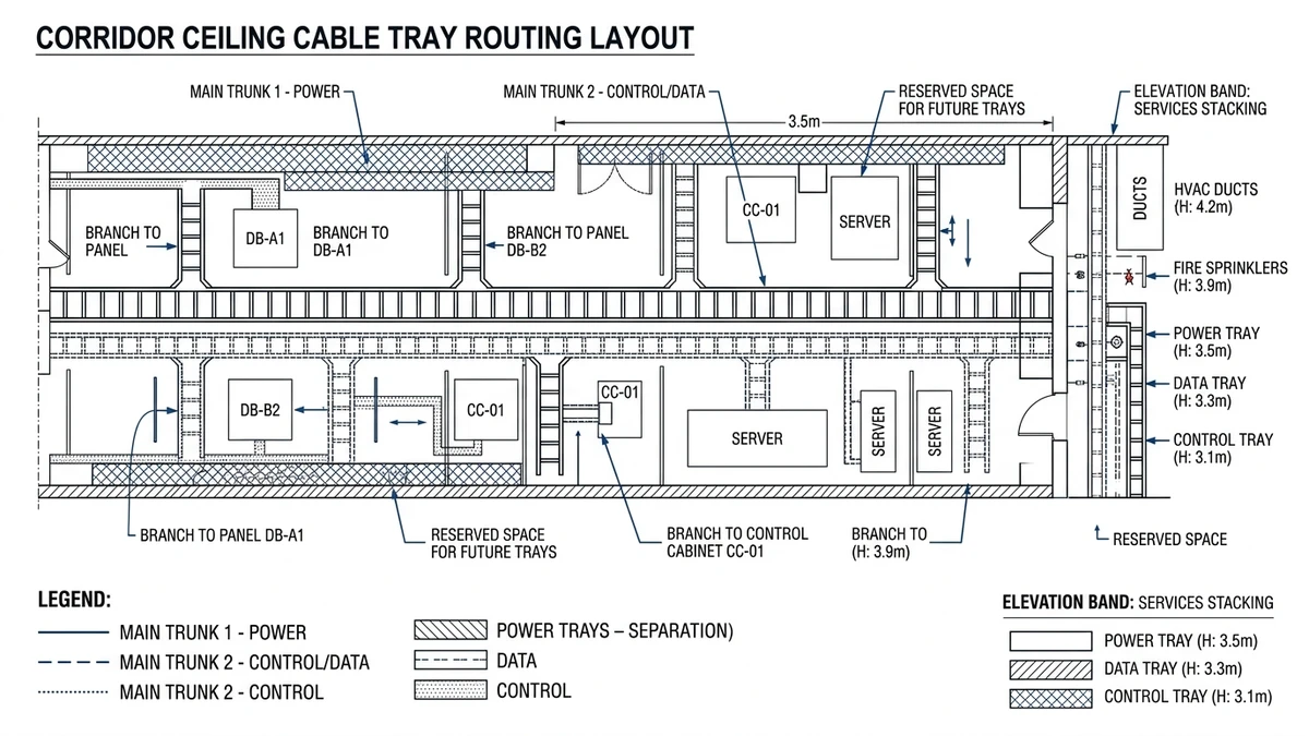
Figure 1. Plan view of cable tray layout showing main trunks, branches, and segregation between power, control, and data trays.
[Expert Insight] Layout Decisions That Prevent Rework
Fixing tray elevations early and coordinating other services around them significantly reduces clashes; keeping initial fill ≤40 % means later cable additions usually remain within original span and deflection limits, avoiding mid-project reinforcement.
Supports, Spans, and Load Basics for Safe Tray Installation
Support spacing is not just a catalog choice; it is a structural design decision. For most 300–600 mm ladder trays, you will end up with 2.0–3.0 m spans once you account for cable weight, self-weight, maintenance loads, and any seismic or wind actions and compare them to manufacturer tables and IEC 61537 proof-load criteria.
What Loads Really Control Span
Treat each tray run as a simply supported beam with uniform cable load, tray self-weight, and occasional concentrated loads (people leaning, junction boxes). Doubling cable load from 40 kg/m to 80 kg/m at the same 3.0 m span roughly doubles bending moment and can push deflection beyond L/200, especially once covers add 2–5 kg/m. As a field rule, keep light control-cable ladders to 3.0 m spans only when total design load is ≤75 kg/m, and otherwise use 2.0–2.5 m spans unless the vendor explicitly approves longer.
Support Configuration and Direction Changes
Place supports within about 300–600 mm of elbows, tees, and vertical drops so fittings do not behave as long levers. Vertical trays need bracing near the top and at intermediate levels, not just at the base, and in seismic areas small diagonal braces at roughly 3–6 m intervals are often more effective than simply choosing heavier ladder. Where trays share steel with busway, check combined reactions against the supporting member’s capacity.
Quick Field Checks Before Fixing Supports
Before drilling, estimate cable load using schedule data, not visual judgment; compare proposed spans with manufacturer load classes, defaulting to 2.0 m when in doubt for heavily loaded ladders. Confirm anchor bolts and threaded rods are rated for the total design load multiplied by a suitable safety factor (often 1.5–2.0), including any extra from covers, snow, or walkways.
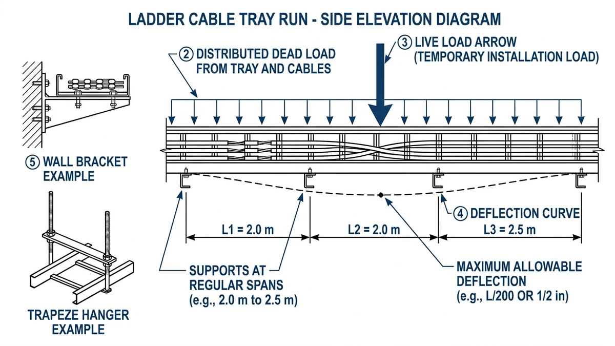
Figure 2. Side elevation of a ladder cable tray run illustrating support spacing, distributed load, and allowable deflection.
[Expert Insight] What Installers Actually Trip Over
Many deflection problems come from undersized support steel twisting or bending, even when the ladder itself is adequate, and joints at heavy risers stay tight far better when supports are placed close to the riser fittings rather than leaving long, lightly supported lever arms.
Step-by-Step Site Installation: From Marking Out to Cable Pulling
A repeatable installation sequence keeps support spacing, levels, and cable routing aligned with IEC 61537 and NEMA VE 2. The steps below assume indoor ladder or wire tray runs with 2.0–3.0 m support spans and 50–150 kg/m design loads.
Step 1 – Site Verification and Marking Out
Confirm the route against latest drawings, including clearances from sprinklers, lighting, ducts, and beams. Mark tray centerline and support positions at the chosen span, adding extra supports near bends, tees, and drops to prevent overstressed fittings.
Step 2 – Install Supports and Hangers
Drill anchors into verified structural material with the required embedment depth, then install threaded rods, cantilevers, or trapeze frames and level them within a few millimetres over typical spans. Torque anchors and bracket bolts to manufacturer values so supports remain stable during cable pulling and vibration.
Step 3 – Mount and Align Cable Trays
Place tray segments on supports starting from a fixed reference, join them with full splice plate bolt sets, and maintain electrical continuity per IEC 61537. After a sample cable load is installed, check midspan deflection; if it is excessive, add or relocate supports before full loading.
Step 4 – Bonding, Earthing, and Inspection
Install bonding jumpers across expansion joints and any non-conductive section, sizing bonding conductors (e.g., 16–35 mm² Cu) per the applicable wiring code and fault levels. Verify tray fill, fire barriers, and separation distances before starting cable pulling so corrections do not require rework of loaded trays.
Step 5 – Cable Pulling and Dressing
Use rated rollers and cable socks and ensure tray geometry respects cable bending radius, typically ≥10× cable OD for large power cables. Pull in a planned sequence (largest power first), then cleat or tie cables at 300–500 mm intervals and label trays and cable groups by voltage and destination for maintenance.
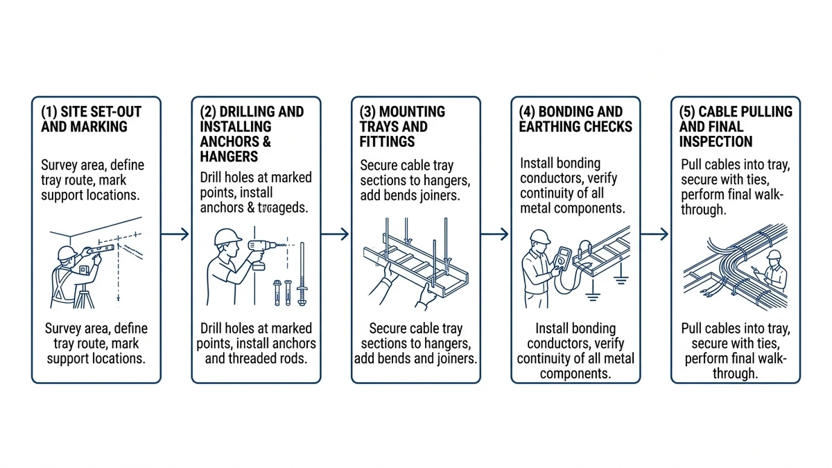
Figure 3. Installation sequence diagram summarizing key steps from site marking to bonding and cable pulling.
Choosing Tray Type, Covers, and Accessories for Field Conditions
Tray selection is a technical trade-off between structural capacity, environment, EMC, and access. The same route may need different tray types in different sections, depending on the field conditions.
Ladder vs. Perforated vs. Solid Trays
Mechanism → number → design consequence:
Ladder cable tray (rungs):
Best for heavy power cables and long spans (2.0–3.0 m) because most stiffness is in the side rails.
Open design improves heat dissipation, so ampacity derating is lower; large LV cables may carry 5–15 % more current than in enclosed supports at similar ambient.
Use for main power distribution, risers, and plant rooms; avoid for many small unsupported control cables or where fine dust must be contained.
Check compatibility of ladders and fittings across widths and support systems (example range at https://xmqj.com/ladder-cable-tray/).
Perforated cable tray:
Flat perforated bottom supports small cables well but usually needs shorter spans than ladder for the same gauge.
Ventilation is moderate, giving more derating than ladder but less than solid; suitable for mixed small control and power at short to medium spans.
Avoid for heavy mechanical loading or where walk-on capability is required; review perforation pattern vs. fixing options and EMC (see https://xmqj.com/perforated-cable-tray/).
Solid-bottom cable tray:
Offers strong physical protection and some shielding but traps heat unless carefully ventilated.
Expect higher derating; many designs assume roughly 10–20 % lower ampacity than open ladder for the same cable set.
Use where shielding or contamination protection is essential, and avoid where high current density exists without room to upsize cables or tray width; ensure thermal and mechanical impacts are reflected in design (see https://xmqj.com/solid-cable-tray/).
Covers, Fire Barriers, and EMC Accessories
Covers protect against falling objects, contamination, and UV outdoors, but they add mass and restrict heat dissipation, often requiring spans to be shortened by about 0.5 m and cable sizing rechecked. Metallic fire barriers or partitions can improve EMC and reduce required separation distances, though they make pulling more complex, so access points must be planned. Bonding accessories such as jumpers and serrated washers are essential, as surface finishes alone rarely guarantee low-resistance continuity where trays form part of the fault-return path.
How Xinma Helps Coordinate Loading, Access, and Support Details in Your Specification
Tray width, cable fill, covers, and support spans interact; changing any one of them affects structural behaviour, derating, and installation sequence. For example, a 400 mm cable ladder at 3.0 m spans with 120 kg/m live load behaves very differently from a 600 mm light wire tray at 2.0 m spans with 60 kg/m—even if both look acceptable on drawings.
Xinma’s role is to treat the cable management system as a coordinated dataset, not a list of catalog codes.
Coordinated Load and Span Validation
Checks for specifiers typically include verifying combined loading (cables, tray, covers, and any snow/wind/walkway) against IEC 61537 or NEMA VE 1 load classes, then adjusting spans (often from 3.0 m down to 2.0–2.5 m) when deflection is high instead of always upgrading tray size. Support type is also matched to load and width so wide multi-tier racks get trapeze frames or seismic bracing where needed (see options at https://xmqj.com/seismic-bracing/).
In corridors where tray schedules were reviewed before procurement, measured deflections on site generally stayed within about 70–80 % of the allowable values, leaving reserve capacity for unplanned additional circuits.
Access, Maintenance, and System Interfaces
Xinma helps coordinate access and maintenance by flagging tray runs above about 2.5 m where defined methods such as walkways or platforms are needed. Fittings and accessories are checked for compatibility with specified tray widths, heights, and corrosion classes so site substitutions are minimized (see https://xmqj.com/cable-tray-accessories/), and transitions between busway and tray take-offs are reviewed so structural and thermal assumptions for both systems stay valid (examples at https://xmqj.com/cable-tray-systems-used-for/).
How to Engage Xinma Technically
To use manufacturer support effectively, share cable schedules with estimated kg/m per route, proposed tray types and widths, allowable deflection, and target spans. Highlight critical circuits where EMC or fire performance is mandatory, and request a coordinated tray and support review rather than just a like-for-like material list, aligning route-specific advice with installation guidance such as https://xmqj.com/cable-tray-installation-guide/.
This article has been updated with explicit source and procurement checks so engineering, EPC, and purchasing teams can verify the recommendations instead of relying only on generic product descriptions. For project use, treat the table below as a starting evidence map and confirm the final requirements against local codes, consultant drawings, and supplier submittals.
Use this source to verify standards, product scope, installation assumptions, or supplier evidence before final specification.
Buyer Verification Checklist
Request drawings that show tray width, depth, side rail profile, bend radius, fittings, and support spacing.
Ask for load tables or engineering assumptions that state test span, load class, and deflection criteria.
Confirm material grade, surface finish, coating method, and corrosion exposure assumptions before comparing prices.
Check whether accessories such as covers, couplers, reducers, clamps, grounding jumpers, and brackets are included.
For EPC or export orders, review packaging, labeling, inspection records, and drawing revision control before shipment.
Frequently Asked Questions
How do I decide the correct cable tray span for my project?
Select span based on total design load (tray + cables + accessories) and allowable deflection, checking manufacturer load tables at the intended span and applying a safety factor; if data is uncertain, keeping ladder trays at 2.0–2.5 m spans usually keeps deflection within L/200–L/250 for typical indoor loads.
When should I use ladder trays instead of perforated or solid trays?
Use ladder trays when you have heavy power cables, longer spans, or critical derating constraints because the side rails carry load efficiently and the open design improves heat dissipation; perforated or solid trays are better reserved for lighter loads, smaller cables, or where additional mechanical protection and containment are needed.
How much spare capacity should I leave in a new cable tray run?
For new installations, designing for an initial fill of about 40–50 % usually provides enough room for future circuits without reworking supports, but for rapidly growing data or process plants you may want to lock in higher spare capacity on main corridors while tightening spans to keep deflection controlled.
How close can I run power and control cables on shared tray systems?
Where codes permit shared structures, maintaining 300 mm separation between LV power and ELV/control and 600 mm to MV or VFD-fed cables is a reasonable starting point, but metallic dividers, shielding, or separate racks should be considered wherever sensitive instrumentation or communication cables run parallel to high-fault-level circuits.
Do I need to bond every cable tray section to earth?
Each metallic tray system should generally be bonded to the protective earth network at regular intervals and across all expansion joints and non-metallic breaks, because relying on mechanical contact alone can leave high joint resistance and reduce the effectiveness of the fault-return path during an earth fault event.
What is the best way to coordinate cable trays with other building services?
During coordination, fix main tray corridors and elevations early, then check clashes and clearances with HVAC, sprinkler, and structural elements so that supports can be anchored into structure and access is preserved; adjusting tray levels by a small amount on the drawings often avoids expensive on-site rerouting later.
Related video: Cable Tray Support Distance: How to Get the Span Right Before You Order
Use this page as the implementation hub. It links the practical installation route to support distance, clamps, covers, data center support conditions, and seismic bracing.
Kevin Zheng is a manager linked to Shanghai Xinma Busway & Cable Tray Co., Ltd. He writes technical content on cable tray systems, installation practice, sizing logic, load classes, and related standards for industrial and infrastructure applications.