What Is Cable Tray Support? Core Definition and Role in the System
Cable tray support is the structural hardware that carries the combined weight of cable trays and cables, transfers loads to the building structure, and controls deflection and vibration. It includes brackets, hangers, trapezes, and frames designed for defined spans (typically 2.0–6.0 m) and working loads (often 75–300 kg/m).
In engineering terms, supports turn a cable tray from a loose cable management system into a predictable load-bearing element. The key parameters are span length, load class, allowable deflection, and attachment capacity to beams, slabs, or walls; for example, a 400 mm ladder tray carrying 120 kg/m of power cables may require 2.5 m spans to keep midspan deflection below L/200 and maintain clearances.
Supports also form part of the electrical safety system. Properly bonded metallic supports provide a continuous protective earth path and help manage fault currents and touch voltages, while support material and coating (e.g., hot-dip galvanized steel vs. stainless steel) strongly influence corrosion life in outdoor or industrial environments.
Standards such as IEC 61537 and NEMA VE 2 define how tray systems are tested, selected, and supported so that field installations run close to their rated mechanical and electrical performance, emphasizing a coordinated tray-plus-support system rather than tray strength alone.
What Does the Main Design Decision Look Like?
For most projects, selecting cable tray supports means choosing a support type and span that can carry the design load (typically 50–200 kg/m) within deflection limits (around L/200–L/300), anchor safely to the available structure with reserve for seismic or wind, and maintain access and clearances for the life of the installation.
The rest of this guide shows how different support types behave, how span and load interact, and how to choose and verify supports on real projects.
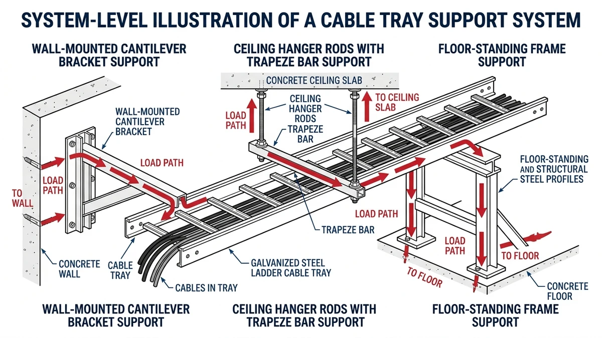
Types of Cable Tray Supports and Their Structural Behavior
Cable tray supports are the structural elements that transfer tray and cable loads into the building or steelwork. Their behavior is governed mainly by span length, connection fixity, and load path under gravity, seismic, and vibration forces.
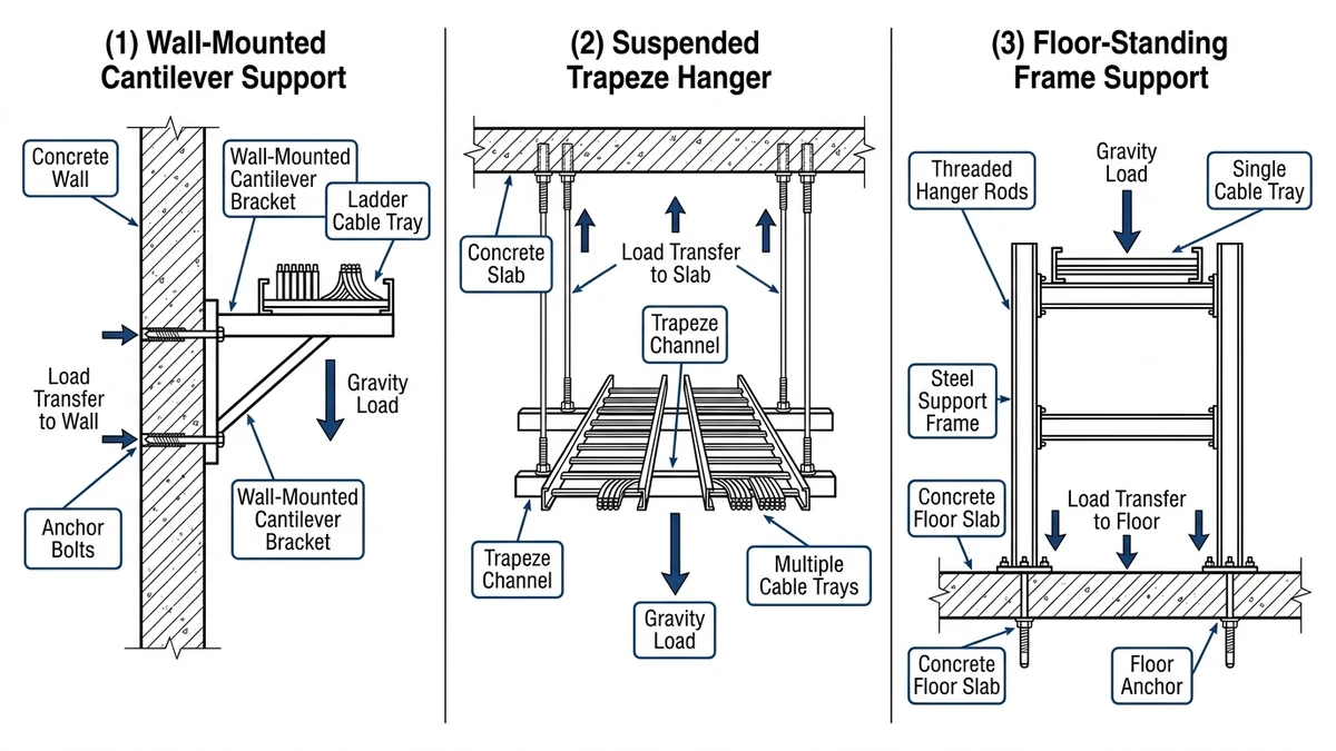
Wall-Mounted and Cantilever Brackets
Wall-mounted cantilever brackets carry tray loads as a horizontal beam fixed at one end and see maximum bending moment and anchor load at the wall. A typical bracket might support a 300 mm ladder over a 1.5 m span with up to 75 kg/m load, provided anchor pull-out/shear and bracket deflection (e.g., ≤7.5 mm at L/200) are within limits.
Use these where walls are strong and continuous; avoid weak blockwork or cracked concrete unless you add through-bolts or backing plates to restore capacity at the connection.
Ceiling-Suspended (Rod and Channel) Systems
Ceiling-suspended systems use threaded rods in tension and transverse channels to hang trays below slabs or beams, but rods must also resist buckling or sway if subject to uplift or lateral loads. Long rod drops (≥2.0–2.5 m) often need increased diameter or bracing, as undersized or unbraced rods allow noticeable sway and vibration when heavy equipment starts.
A transverse channel supporting a wide tray (e.g., 600 mm over 2.5 m) must be sized to limit midspan deflection under combined cable and tray weight, especially in multi-tier arrangements.
Floor-Mounted Racks and Tiered Support Frames
Floor-mounted frames carry one or more tray tiers between uprights, with posts anchored to slabs or foundations to resist vertical load and lateral actions. Design focuses on baseplate and anchor group capacity under combined shear, tension, and overturning, plus overall frame drift under seismic loads, which usually drives the need for cross-bracing on tall frames (e.g., 3.0 m high).
These supports are favored for heavy power routes (often 150–200 kg/m) and where overhead structure is unavailable or congested.
Trapeze and Multi-Tier Assemblies
Trapeze supports use two or more vertical rods with a transverse channel to carry several trays side by side, creating efficient grouped supports but higher concentrated loads on the host structure. Design must account for eccentric loading when trays are offset from the rod line and for unequal loading between tiers, with the heaviest tier (often the lowest) usually governing span (commonly 2.0–3.0 m).
On retrofit work, underdesigned trapezes often show excess sag or rod elongation once future cables are added, indicating a need for shorter spans or deeper channels.
Beam Clamps, Attachments, and Local Fixity
Where trays connect to steel beams, beam clamps or angles determine whether the support behaves closer to pinned or fixed, which in turn affects midspan deflection, vibration, and seismic load paths. A tray that meets deflection criteria at 3.0 m with a rigid end may need 2.0 m spans when connected with flexible clamps providing little rotational restraint.
Treat connection stiffness as a design variable, and in seismic design add bracing or struts where flexible, clamp-type connections would otherwise permit excessive sway.
[Expert Insight]
– For calculations, assume connections are closer to pinned unless you have test data or details proving fixity; this yields safer deflection predictions.
– Near rotating equipment, maintenance records show fewer loosening issues when beam clamps include anti-vibration washers and double nuts.
How Support Spacing and Loading Drive Design Decisions
Support spacing and loading are linked: for a given tray profile, increasing span sharply increases deflection and stress under the same load, so designers balance span, expected load (kg/m), and deflection limits to keep systems reliable.
In practice, once tray type is fixed, support spacing is the main lever: shorter spans cost more steel and labor; longer spans increase deflection, vibration, and risk of overloading.
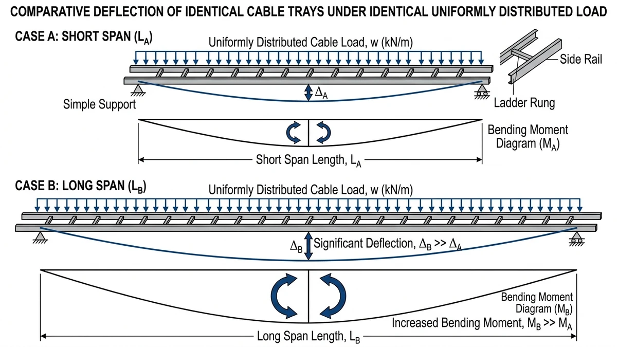
Span, Load, and Deflection: The Beam Behind the Tray
A cable tray behaves like a simply supported beam with uniformly distributed load, and midspan deflection is roughly proportional to w·L⁴/(E·I), so doubling span (2.0 m to 4.0 m) increases deflection 16-fold. A 300 mm steel ladder carrying 60 kg/m may meet IEC 61537 limits at 3.0 m but not at 4.0 m, even though the tray does not structurally “fail.”
Excessive deflection (e.g., >15 mm) can create low spots that trap water or dust, cause cables to bunch and alter fill ratio and ampacity, and overstress joints and splice plates, particularly in seismic areas.
Load Components That Set Spacing
When choosing spacing, include:
Dead load – tray (about 5–15 kg/m) plus cables (often 20–100 kg/m, higher for large MV).
Superimposed loads – temporary worker loads (800–1,200 N point), snow/ice outdoors, small mounted equipment.
As total load increases, you either shorten spans (e.g., 3.0 m to 2.0 m) or upgrade to a higher load class tray or stiffer support to keep stresses and deflections within allowable limits.
[Expert Insight]
– IEC 61537 tables are based on specific test loads and deflection criteria; if you do not recalc with your actual cable mass, real deflection can exceed catalog assumptions by 20–30 %.
– For long outdoor runs with large temperature swings (±30 °C), one fixed point every 30–40 m with sliding supports elsewhere usually keeps anchor forces and cracking under control.
Selecting Cable Tray Supports for Real Projects
Selecting supports means converting catalog data into spans, loads, and fixings that control deflection, vibration, and maintenance. Key inputs are tray type, load per metre, environment, and available structural fixing points.
Step 1 – Define Tray Route and Structural Fixing Points
Map tray routes and note actual beams, slabs, walls, or floors where supports can land; a nominal “3.0 m span” is irrelevant if structural gaps are 4.2 m. Your maximum support spacing must be no greater than the largest viable structural gap, or you must introduce secondary steel, cantilevers, or trapezes.
In multi-route corridors, aligning trays to common support lines often reduces hanger count significantly while simplifying coordination with other services.
Step 2 – Calculate Design Load per Metre
For each segment:
Sum cable masses from datasheets using the intended fill ratio (kg/m).
Add tray self-weight and a future allowance, typically 25–50 %.
Convert significant point loads (e.g., an 80 kg box) into an equivalent distributed load over about 1.0–1.5 m.
Compare with the tray’s rated kg/m at the proposed span (IEC 61537 or NEMA VE 1). If a tray is rated 150 kg/m at 2.5 m but you need 180 kg/m, either shorten the span (e.g., to 2.0 m) or upgrade to a higher load class tray/support.
Step 3 – Select Support Type and Configuration
Match support type to route and environment:
Vertical threaded rod hangers for indoor ceilings with typical 2.0–3.0 m spans, braced when rod drops exceed about 2.0 m.
Wall brackets for side-mounted trays; check wall capacity and anchor type for pull-out and shear.
Floor stands or strut frames when overhead steel is lacking or loads are heavy (150–200 kg/m).
Braced frames and sway restraints in outdoor or seismic zones where uplift or lateral movement is critical.
Stiffer supports lower midspan deflection and vibration, which is important for wide ladders (600–900 mm) with heavy power cables or sensitive control circuits.
For system-level choices between ladder, perforated, and solid trays, see Xinma’s guidance on complete cable tray systems.
Step 4 – Check Deflection, Clearance, and Maintenance
Before finalizing:
Confirm deflection stays within project limits (often L/200–L/250), so a 3.0 m span typically should not deflect more than about 12–15 mm.
Maintain clearances to other services, structural elements, fire barriers, and access routes.
Ensure maintenance access: technicians must be able to reach covers, supports, and junction points and pull additional cables without major rework.
If a typical span noticeably bounces under the brief load of an 80 kg person, support stiffness is marginal and usually requires shorter spans, deeper sections, or bracing.
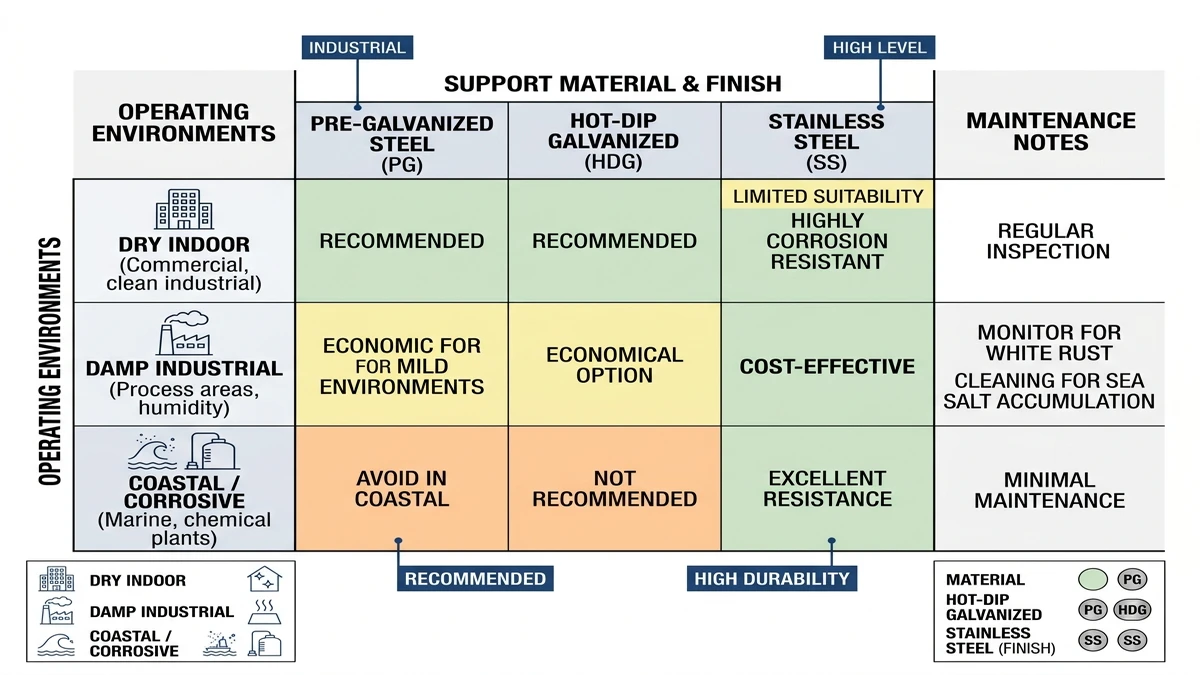
Step 5 – Coordinate Corrosion and Fire Requirements
Match support material and coatings to tray material and environment (e.g., hot‑dip galvanized, epoxy-coated, stainless), avoiding galvanic corrosion from incompatible metal pairings in damp or coastal areas. Where fire resistance is specified, ensure that supports, anchors, and spacing align with the tested assembly and configuration.
Applying These Trade-Offs with Xinma: Coordinating Loading, Spans, and Support Details
Cable tray support choices influence allowable spans (commonly 2.0–3.0 m for standard loads), working load (around 50–200 kg/m depending on class and span), deflection limits (often L/200–L/300), and ampacity derating where trays are densely filled, stacked, or covered.
Because Xinma designs and rates complete systems, the focus is on trays, fittings, and supports working together, including selecting tray profiles and materials that meet load class at target spans, checking that proposed spans stay within deflection and dynamic limits for the cable schedule, and confirming fittings, splices, and supports share consistent structural and corrosion specifications.
Reviews of large industrial runs often reveal hidden load increases from covers, future cable allowances, and multi-tier frames; adjusting span tables at design stage typically avoids on-site additions of unplanned hangers and reduces variation orders.
When fixing span tables, specifying support types, or checking combined loading, having Xinma review trays, fittings, and supports as an integrated design before IFC can also coordinate with busway supports—see the busway system page—and with seismic restraint design where required.
From there, detailed product choices follow:
Use ladder-type configurations with appropriate ladder cable tray designs for high-load or outdoor runs.
Apply seismic bracing solutions where design accelerations justify restraint or where rod sway/uplift is a concern.
For dimensioning and future load planning, Xinma’s guide on cable tray dimensions and sizing logic supports correct route and support selection.
This article has been updated with explicit source and procurement checks so engineering, EPC, and purchasing teams can verify the recommendations instead of relying only on generic product descriptions. For project use, treat the table below as a starting evidence map and confirm the final requirements against local codes, consultant drawings, and supplier submittals.
Use this source to verify standards, product scope, installation assumptions, or supplier evidence before final specification.
Buyer Verification Checklist
Request drawings that show tray width, depth, side rail profile, bend radius, fittings, and support spacing.
Ask for load tables or engineering assumptions that state test span, load class, and deflection criteria.
Confirm material grade, surface finish, coating method, and corrosion exposure assumptions before comparing prices.
Check whether accessories such as covers, couplers, reducers, clamps, grounding jumpers, and brackets are included.
For EPC or export orders, review packaging, labeling, inspection records, and drawing revision control before shipment.
Frequently Asked Questions
How do I decide the right span for cable tray supports?
Start from the manufacturer’s span table for your tray type and load class, then choose a span so your calculated cable load plus future allowance stays within the rated kg/m at that span while keeping deflection within L/200–L/300.
When should I use floor-mounted racks instead of ceiling hangers?
Use floor-mounted racks when ceiling steel is sparse or heavily loaded, or when tray plus cable loads exceed about 150–200 kg/m and would require impractically dense ceiling hangers.
How much future capacity should I allow in cable tray support design?
Many engineering teams allow 25–50 % extra cable mass compared with initial installation, provided the resulting total load still fits the tray’s tested load class at the chosen span.
Do seismic requirements change the choice of cable tray supports?
Yes. Seismic design usually drives shorter spans, braced frames, and detailing that prevents uplift or sway, especially in regions where design accelerations of about 0.3 g or higher are specified.
What checks are essential before specifying anchors for cable tray supports?
Verify base material type and strength, required edge distances, combined tension and shear from tray loads plus seismic or wind, and confirm the selected anchor has appropriate test data for that substrate and loading.
How does support design affect cable ampacity in tray systems?
Support design influences cable spacing, use of covers, and multi-tier arrangements; these affect cooling and may require ampacity derating compared with open-air assumptions.
Related video: Cable Tray Support Distance: How to Get the Span Right Before You Order
Engineer support guide: connect this article to the main implementation hub
This support introduction should work as a technical spoke, not a duplicate hub. Use the main installation and support guide for the full layout-to-installation path.
Kevin Zheng is a manager linked to Shanghai Xinma Busway & Cable Tray Co., Ltd. He writes technical content on cable tray systems, installation practice, sizing logic, load classes, and related standards for industrial and infrastructure applications.