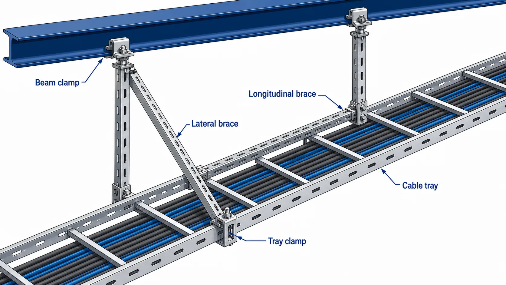
Cable tray runs in seismic zones need more than normal hanger spacing. A standard trapeze support carries gravity load; it does not reliably stop lateral sway, longitudinal movement, anchor pullout, or cable spill during ground motion. A coordinated seismic bracing system uses strut channels, clamps, connectors, anchors, and tray interfaces as one load path from the cable tray to the building structure.
Overview of a cable tray seismic bracing load path from tray rail to structure.
This guide is written for EPC engineers, MEP contractors, procurement teams, and site inspectors working on industrial plants, data centers, metro and tunnel projects, and commercial buildings. It explains when bracing is needed, how support layout should be reviewed, which components matter, and what must be checked before the ceiling is closed or the tray route is energized.
1. When Seismic Bracing Is Required for Cable Tray
Seismic bracing requirements usually come from the project building code, the structural design basis, local authority requirements, or the electrical and MEP specification. The correct starting point is the project seismic design category, site acceleration data, equipment importance, and the cable tray route height. A generic spacing rule is not enough.
For cable tray systems, restraint is commonly required when one or more of these conditions apply:
The tray carries high-density power cables or critical communication cables.
The route is suspended above occupied areas, equipment rooms, evacuation paths, or production lines.
The tray feeds emergency power, fire alarm, control, or data center systems that must remain available after an event.
The installation is in a facility where inspection requires documented brace location, anchor type, and component traceability.
Tray type also affects the calculation. A ladder cable tray carrying power cables has a different loaded weight and side-rail interface than a light-duty tray used for data cabling. Before selecting braces, confirm tray self-weight, cable fill, route elevation, support type, and the structural element that will receive the brace force.
IEC 61537 is a useful reference for cable tray performance classification and test methods, but seismic bracing still needs project-specific review by the engineer of record. Use published standards and local code requirements as verification sources rather than inventing a clause number.
2. Brace Layout: Direction, Interval, and Load Path
A good seismic brace layout answers three questions: which direction is being restrained, where does the force go, and can every connection in that path carry the design load?
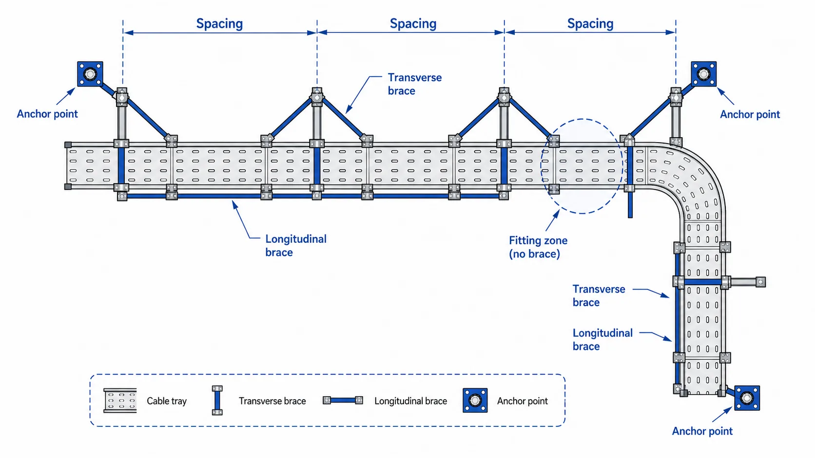
Brace layout should confirm direction, interval, and structural landing points.
Transverse braces control side-to-side motion across the tray route. Longitudinal braces control movement along the direction of the tray. Both directions matter on long suspended routes. If only transverse braces are installed, the tray can still shift along the run, stressing splice plates, fittings, and cable bend zones.
Brace intervals should be calculated from loaded tray weight, seismic force coefficient, support elevation, and allowable component capacity. In early design, engineers often mark preliminary brace zones on the route drawing, then adjust after coordination with ductwork, pipework, structural beams, and access panels. Field teams should not move a brace location simply because it is inconvenient. A moved brace changes the force path and may require engineering approval.
The load path should be visible in the drawing and inspectable on site:
Tray rail or rung to tray clamp
Tray clamp to brace connector
Brace connector to strut channel
Strut channel to beam clamp, anchor, or insert plate
Structural landing point to the building frame
Do not let the brace bear against a splice plate, cable tray cover, or unsupported fitting edge. For routes with elbows, tees, reducers, or vertical transitions, confirm the fitting geometry against the cable tray fittings schedule before fixing brace locations.
3. Components and Installation Sequence
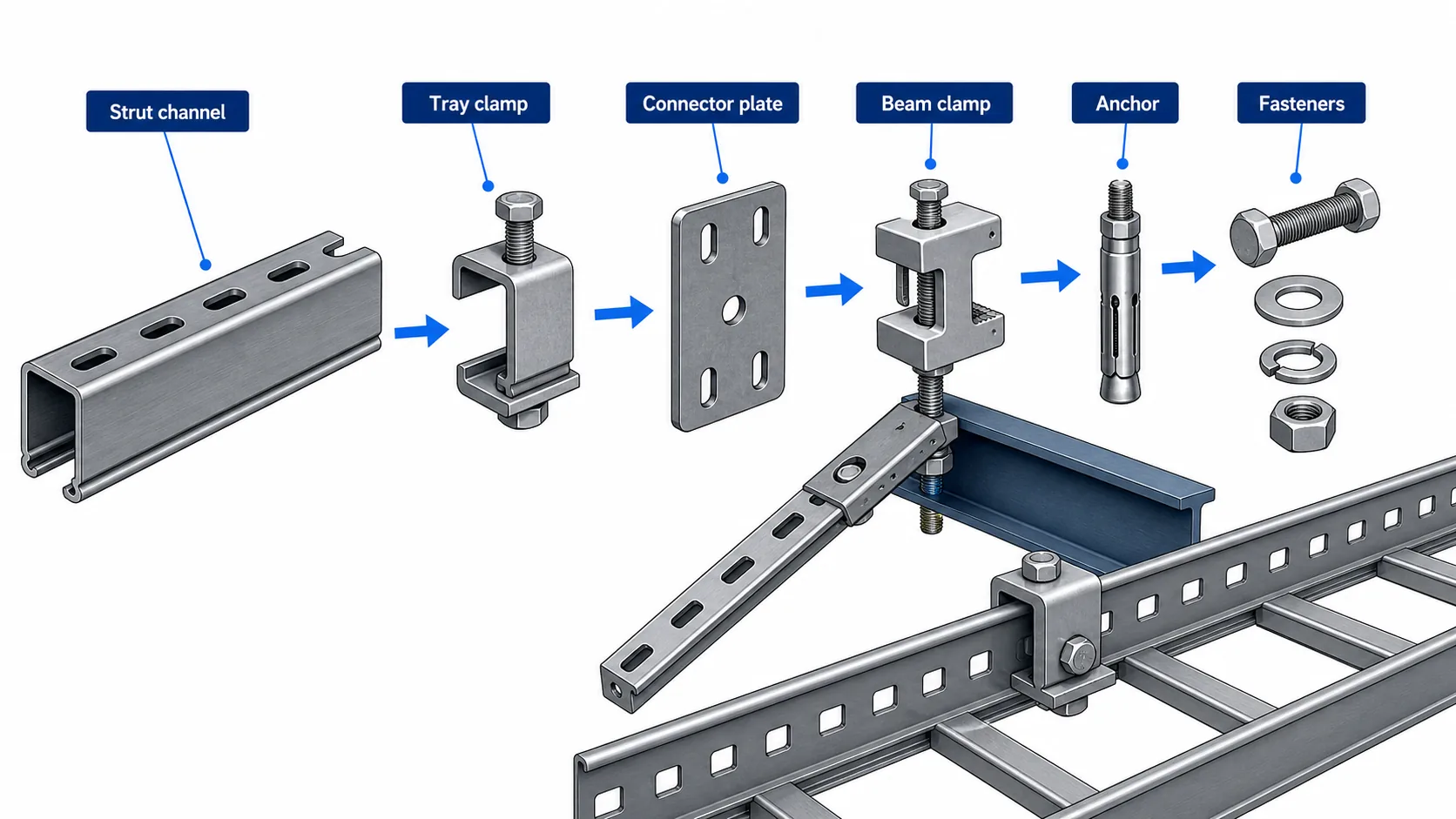
A seismic brace package is a coordinated assembly, not a collection of similar-looking parts. The common component groups are strut channel, beam or concrete anchors, tray clamps, connector plates, bolts, washers, and sometimes back-to-back channel members for higher force zones.
A seismic brace package depends on matched components, not isolated hardware.
Strut channels act as the primary tension and compression members. Channel depth, wall thickness, and finish should match the calculated brace load and installation environment. Back-to-back strut can be required where single-channel capacity or buckling resistance is not enough.
Beam clamps and concrete anchors transfer the brace force into structure. For steel beams, check flange thickness and clamp orientation. For concrete, verify anchor type, embedment depth, edge distance, concrete strength, and curing requirements for adhesive anchors. Anchor substitution is one of the fastest ways to fail inspection because the calculated capacity no longer matches the installed hardware.
Tray clamps must match the cable tray rail profile. A clamp that looks acceptable on one tray series may not seat correctly on another rail height or flange width. For projects using mixed tray types, review clamp compatibility with cable tray accessories before bulk procurement.
A practical installation sequence is:
Mark brace positions from the approved layout drawing.
Verify the structural landing point before drilling or clamping.
Install anchors or beam clamps with the specified orientation and torque.
Assemble strut members and connector plates.
Attach tray clamps without deforming the tray rail.
Align brace angle and geometry.
Torque bolts, mark completed fasteners, and record the hold point.
4. Common Mistakes and Field QA Checklist
Most bracing problems are not caused by missing hardware. They are caused by a broken load path, undocumented substitution, or a site adjustment that was never reviewed.
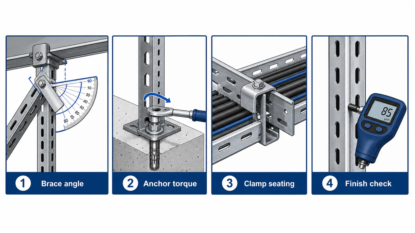
Brace angle, anchor torque, tray clamp seating, and finish continuity are key hold points.
Common mistakes include:
Installing a vertical hanger and calling it a seismic brace.
Using only transverse braces on a long route that also needs longitudinal restraint.
Moving brace locations around ductwork without engineering approval.
Mixing hot-dip galvanized strut with zinc-plated hardware in corrosive areas.
Attaching a brace to a weak fitting edge instead of a tray rail or approved bracket.
Leaving field-cut strut ends uncoated on outdoor or chemical-exposure routes.
Accepting unmarked anchors with no batch traceability.
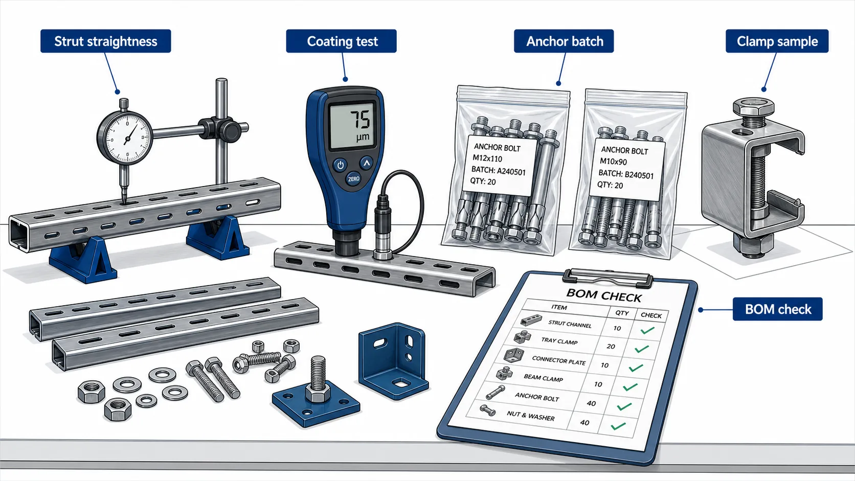
Before closeout, the site team should verify:
Brace angle is within the design drawing tolerance.
Anchor type, embedment, and torque are recorded.
Strut size and finish match the approved bill of materials.
Tray clamps seat fully without rail deformation.
Longitudinal and transverse brace intervals match the drawing.
Any field relocation is recorded and approved.
Critical routes are photographed before ceiling closure.
For broader tray support coordination, review the cable tray installation guide alongside the seismic brace drawing. Gravity support spacing and seismic restraint are related, but they are not the same design check.
5. Procurement Verification and Supplier Documentation
Procurement should treat seismic bracing as a matched system. Buying channels, clamps, anchors, and connectors from unrelated suppliers can create fit problems and documentation gaps even when each part appears acceptable by itself.
Procurement verification reduces substitution risk before site installation.
For EPC and contractor buyers, the purchase package should include:
Component model codes tied to the approved drawing revision
Material grade and finish for strut, clamps, and connector plates
Anchor certificates or mechanical property records
Dimensional drawings for clamp interfaces
Coating records for galvanized, epoxy-coated, or stainless components
Packing lists that separate brace sets by route or installation zone
Shanghai Xinma manufactures cable tray, fittings, accessories, and seismic bracing components within the same product ecosystem. That matters when the clamp interface must match the tray rail and when a project needs repeated deliveries across several phases. The value is not a marketing ranking; it is the ability to keep model codes, finishes, and geometry consistent from bill of materials to site inspection.
When specifying Xinma products, use the live seismic bracing product page as the primary landing page, and cross-check tray compatibility against the relevant cable tray system and accessory pages before finalizing the order.
Frequently Asked Questions
What is the difference between a cable tray support and seismic bracing?
A cable tray support carries gravity load. Seismic bracing restrains lateral and longitudinal movement during seismic motion. A tray may need both systems: normal hangers for vertical support and diagonal or rigid braces for horizontal restraint.
How far apart should seismic braces be installed on a cable tray route?
Spacing depends on the loaded tray weight, seismic design force, route elevation, brace direction, and component capacity. Use the engineer of record’s calculation and approved layout drawing rather than a universal distance.
Can seismic bracing be added after the cable tray is already installed?
Yes, but it requires route inspection. The installer must verify structural anchor points, tray rail condition, clearance around fittings, and whether existing supports can remain. Some anchor locations may need redesign if access is limited.
Which cable tray types can use seismic bracing clamps?
Ladder tray, perforated tray, and solid-bottom tray can all be restrained, but clamp compatibility depends on rail height, flange width, material, and finish. Confirm the clamp model against the tray section before ordering.
What documents should a supplier provide?
Ask for component data sheets, model code schedule, material and finish information, anchor documentation, dimensional drawings, and packing lists tied to the project BOM. For regulated projects, the engineer may also require calculation inputs.
Do seismic bracing components need corrosion protection?
Yes. Outdoor, tunnel, coastal, and chemical environments need finish selection that matches the exposure. Hot-dip galvanizing, stainless steel, or duplex coating may be required depending on the project specification.
How do fittings affect seismic brace layout?
Elbows, tees, reducers, and vertical transitions interrupt straight tray runs and create local stress points. Brace locations should be coordinated after fitting positions are fixed, and the brace should transfer load through approved tray rail or bracket interfaces rather than unsupported fitting edges.
Kevin Zheng
Kevin Zheng is a manager linked to Shanghai Xinma Busway & Cable Tray Co., Ltd. He writes technical content on cable tray systems, installation practice, sizing logic, load classes, and related standards for industrial and infrastructure applications.