What Cable Tray Dimensions Buyers Must Check First in 2026
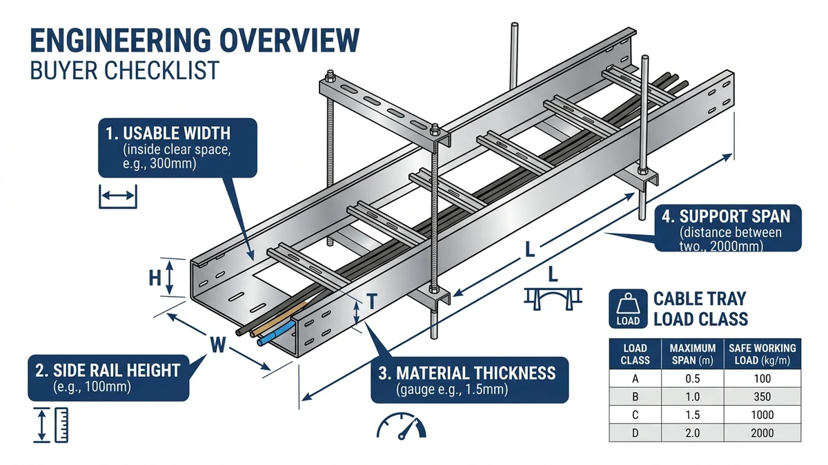
For cable tray dimensions in 2026, specifiers should first confirm tray width, side height, and working height under load, because these govern cable fill, ampacity, and structural safety. IEC 61537 and NEMA VE 1 require trays to be selected so deflection, clearances, and fill ratios remain within tested limits at the intended span.
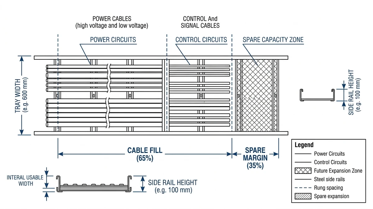
Start with tray width versus cable volume: a 300 mm ladder tray at 50 mm side height might safely carry about 40–60 control cables (Ø10 mm) at 40–50 % fill, while a 600 mm tray is often needed for mixed power and control. Side height (typically 50–150 mm) controls allowable cable stacking and containment during fault or seismic events.
Next, relate these dimensions to your planned support span (e.g., 2.5 m vs 3.0 m): a wider, high-sided tray of the same material will deflect more under the same 100 kg/m load, potentially breaching the L/200 deflection criterion in IEC 61537. In practice, this is where many projects either over-specify tray size or under-specify support spacing.
Choosing Cable Tray Width and Side Height from Real Cable Loads
Cable tray dimensions should be chosen from actual cable loads, not from catalogue habit. Width is driven by cable outside diameters and fill; side height is driven by stack height, bending radius, and future capacity. The fastest way to get this wrong is to skip the numbers.
Step 1 – Quantify the Real Cable Load
List each cable type on the route with:
Outside diameter (e.g., 3 × 240 mm² power cable, OD = 45 mm).
Mass per meter (e.g., 3.5 kg/m).
Count how many of each run in the tray segment (e.g., 6 power + 24 control).
Calculate:
Total cable width demand (ladder/wire tray): sum of cable diameters across the tray.
Total linear load: kg/m = Σ(cable mass per meter × quantity). Mixed power/control routes often reach 40–80 kg/m and occasionally 100 kg/m in dense industrial runs.
Then compare resulting kg/m against the tray’s rated load class from IEC 61537 or NEMA VE 1 for the chosen support span (e.g., 2.0 m vs 3.0 m). Do not assume a rating at 2.0 m applies at 3.0 m.
Step 2 – Select Tray Width from Fill and Routing
Set a maximum fill ratio for the usable width:
Power and control: typically 40–60 %.
Telecom/data: often limited to 30–40 % to control bending and heat.
Convert load to width:
Example: 6 × 45 mm power laid in one layer need ≈ 270 mm.
Add spacing (≈10–20 mm per cable) and side clearance (≥25 mm per side).
Result: 270 + 5×15 + 50 ≈ 395 mm → select next standard width, 400 mm or 450 mm.
Reserve at least 20–30 % free width for future circuits or rerouting. This is usually cheaper than adding a second tray later.
Step 3 – Choose Side Height from Stack and Radius
Side height must contain the cable stack and respect bending radius at edges and fittings:
Estimate maximum stack height:
If you accept 2 layers for 45 mm cables: stack ≈ 90 mm.
Add 10–15 mm clearance: ≈100 mm total.
Compare with standard side heights (e.g., 50 mm, 75 mm, 100 mm, 150 mm):
For 1 layer of ≤25 mm control cables, 50 mm sides are usually adequate.
For multi-layer power or mixed services, 75–100 mm sides are typical.
150 mm sides are usually reserved for heavy industrial runs, high stacking, or where covers must stay in place under fault conditions.
Check minimum bending radius:
Many power cables require 8–12 × OD (e.g., 45 mm × 10 = 450 mm).
Side height must not force cables to kink over the edge or fittings; otherwise insulation stress and local heating increase.
Step 4 – Iterate with Load Class and Supports
Once provisional width and side height are chosen:
Re-check load rating: a 600 mm tray at 3.0 m span may drop from 150 kg/m to 100 kg/m if a lighter side rail profile is used.
If tray capacity is insufficient:
Reduce support span (e.g., from 3.0 m to 2.0 m).
Move to a higher load class or thicker profile.
Split the route into parallel trays to reduce kg/m on each.
In our deployments, projects that accepted a 0.5 m reduction in span often avoided moving to a heavier tray series, saving both material cost and seismic bracing complexity.
Step 5 – Apply Consistency Along the Route
Each width/height change introduces fittings, extra supports, and more coordination checks. Designers typically standardize on:
150–300 mm width, 50 mm sides for light control and instrumentation.
300–450 mm width, 75–100 mm sides for mixed runs.
600–900 mm width, 100–150 mm sides for dense power or data highways.
Change sizes only where load, cable type, or environment shifts enough to justify a new tray size; otherwise installers will spend more time adapting than installing.
Figure 1. Plan view illustrating how cable tray width and side height are chosen from cable fill, spare capacity, and segregation needs.
[Expert Insight]
– In field reviews, most “mystery hot spots” in trays trace back to underestimated cable count or future additions, not to the original sizing. Reserve width early.
– For long production lines, grouping cables by load type (motors vs instrumentation) on separate trays often improves both thermal performance and troubleshooting.
Structural Dimensions: Thickness, Span, and Load Class Explained
For a cable tray, thickness, span, and load class are three sides of the same structural problem: how much the tray bends under load. Stiffer trays (thicker metal, deeper section, shorter spans) deflect less for the same cable weight, directly affecting support spacing, vibration, and long‑term safety.
How Thickness Controls Stiffness
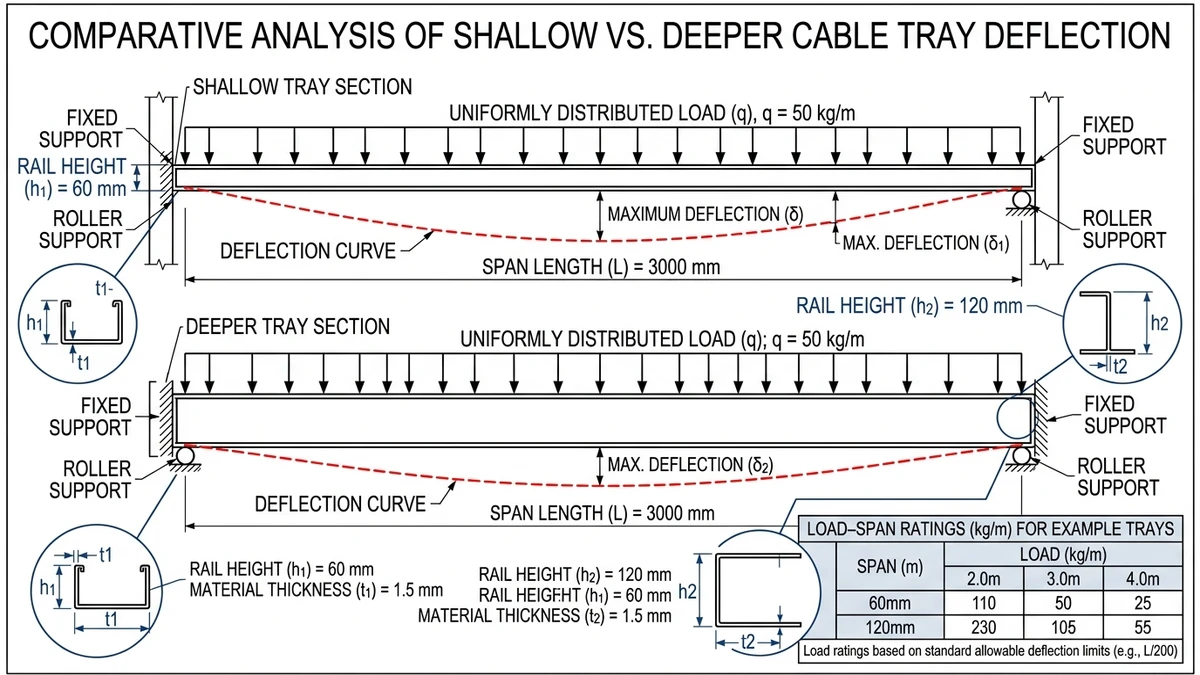
Most cable ladder side rails behave like beams. Their bending stiffness is proportional to E·I, where E is the elastic modulus and I is the section moment of inertia. For the same profile and span, increasing steel thickness from 1.5 mm to 2.5 mm can roughly double I, cutting deflection by about half.
Design consequence:
Thinner trays (≈1.2–1.5 mm) suit light control cables and short spans ≤1.5 m.
Heavier trays (≈2.0–3.0 mm) are needed for power cables, wider trays (≥600 mm), or spans ≥2.5 m.
On site, undersized thickness shows up as visible sag after cables are pulled or as noticeable vibration when nearby machinery runs. Maintenance teams often flag these sections long before a formal inspection.
Span vs. Deflection: Why 3 m is Not “Just 50% More” Than 2 m
For a uniformly loaded tray, midspan deflection δ scales roughly with span³ (L³). If you increase span from 2 m to 3 m:
L increases by 1.5×.
δ increases by ≈1.5³ ≈ 3.4×.
So a tray that deflects 4 mm at 2 m could deflect around 14 mm at 3 m under the same 100 kg/m load. This is why manufacturers publish different load ratings for 1.5 m, 2.0 m, or 3.0 m support spacing, even with identical tray profiles.
Selection trade‑off:
Longer spans reduce hanger and labor count, but increase deflection and may demand thicker trays.
Shorter spans increase hanger count but allow lighter tray sections and often make seismic bracing simpler.
Interpreting Load Class in Real Design
IEC 61537 load classes couple three parameters:
Test span (e.g., 1.5 m, 2 m, 3 m)
Proof load (e.g., 75, 100, 150, 200 kg/m)
Maximum allowable deflection (often L/200–L/250)
Example: a tray tested at 3 m span and 200 kg/m, with deflection below L/200 (≈15 mm), is not intended to be run at 200 kg/m in permanent service. A pragmatic approach:
Compute cable weight per meter and add 10–20 kg/m for future additions.
Compare to the tested load at your actual span.
Use 60–80 % of the test load as a working design value, depending on your risk posture.
If you change thickness, span, or cable loading, you must re‑check the load class curve for that tray series. IEC and NEMA type tests do not automatically transfer across these changes.
Figure 2. Comparison of cable tray structural dimensions showing how span length and side rail profile affect load capacity and deflection.
[Expert Insight]
– When we review installations that have developed excessive sag, almost all were originally sized from “rule-of-thumb spans” without checking the load class table for that exact tray profile.
– For critical routes (e.g., data center main runs), specifying maximum allowable deflection in millimeters at design stage forces the project team to coordinate support spacing instead of accepting whatever fits the structure.
Fittings, Clearances, and Site Constraints That Change “Correct” Dimensions
Even if cable tray dimensions are correct on paper for load and fill, fittings, clearances, and building geometry can force changes at specific locations. Selection becomes a coordination task across disciplines, not just a catalog pick.
Fittings That Expand the Required Envelope
Elbows, tees, crosses, and reducers often need more space than straight tray:
A 600 mm wide horizontal elbow can require 900–1 000 mm of plan width when you include side rails, splice bars, and minimum bend radius for 90 mm diameter power cables.
Vertical risers may need 300–500 mm extra height to respect cable bend radius and maintain cover continuity.
Checklist:
Confirm every major direction change has a matching fitting size and type (inside/outside vertical, horizontal, tee, cross).
Check fitting lengths against available corridor space; many 90° bends approach 1 m in developed length.
Plan reducers where congestion forces you to narrow tray width, and confirm capacity still meets cable load.
Electrical and Safety Clearances
Codes and standards require minimum separations to control interference, access, and safety:
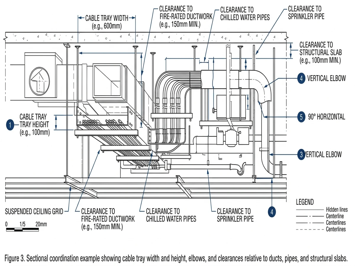
Maintain typical 300 mm horizontal separation between power trays and sensitive control/IT trays unless you use metallic barriers or separate levels.
Keep at least 50 mm from sprinkler mains or process pipes; increase separation for hot piping (>60 °C) to avoid thermal derating of cables.
Checklist:
Identify fire alarm and communication routes and reserve vertical separation or metallic dividers.
Check that tray, supports, and covers do not obstruct access panels, luminaires, or AHU doors.
Validate that finished tray height still leaves code working space around switchboards and panels (often 1 000–1 200 mm in front).
Architectural and Structural Constraints
Beams, ducts, and ceiling height frequently dictate the practical combination of tray width and stack configuration:
In a 2.7 m ceiling corridor with 600 mm deep ducts, available space for tray and supports might only be 250–300 mm. That can cap tray side height at 50–75 mm and force multiple 300 mm trays instead of a single 600 mm tray.
Checklist:
Cross-check tray widths against corridor widths, door heads, and planned cable drops; minimize last‑minute transitions.
Coordinate hanger types and spacing with structural steel or slab inserts; verify that 3 m spans are actually buildable along the route.
Mark congested pinch points (above MCC rooms, near risers) and decide where to stack trays or run side‑by‑side instead of increasing single-tray width.
Maintainability and Access
Dimensions that work on day one must also support years of maintenance:
Leave at least 150–200 mm side access to open covers, clamp new cables, and inspect the tray.
Avoid tray stacks beyond realistic reach; top trays above 2.2 m are easier to maintain with hinged or removable covers.
Checklist:
Confirm fittings and stacked trays do not obstruct junction boxes, dampers, or valves.
Identify sections where spare capacity is mission‑critical and confirm there is physical space to widen or add another tray later.
Figure 3. Sectional coordination example showing cable tray width and height, elbows, and clearances relative to ducts, pipes, and structural slabs.
How Xinma Helps Coordinate Dimensions, Loading, and Support Details
Across real projects, three patterns have consistently caused rework on cable tray systems: width mismatched to fill (e.g., 300 mm trays pushed to 80 % fill), support spans not aligned with load class (e.g., 3.0 m span on a tray tested for 150 kg/m but carrying close to 200 kg/m), and fittings that disrupt the intended support pattern. Xinma focuses directly on these interactions during specification.
Xinma’s engineering team can take your cable schedule, routing sketches, or BIM model and check:
Required tray width versus cable list, applying realistic fill ratios (typically 40–60 % for power, 60–70 % for control) and reserving spare capacity based on project growth assumptions.
Load and span compatibility against the tray’s IEC 61537 or NEMA VE 1 load class, confirming whether 1.5 m, 2.0 m, or 3.0 m support spacing remains within deflection limits for your 100–200 kg/m design loads.
The added mass of covers, dividers, and splice plates, which can add 5–10 kg/m and push a marginal design across the test deflection threshold.
Fitting geometry (tees, offsets, vertical elbows) so hanger locations at corners still respect maximum allowable span and required clearances.
On several industrial layouts we reviewed, a simple re‑spacing of supports around heavy vertical drops reduced midspan deflection by more than 30 %, avoiding a late redesign of tray gauge and side height.
Because tray dimensions, loading, and supports interact, it is risky to “pick a 400 mm ladder tray at 3 m spacing” in isolation. Use your internal standards plus IEC guidance, then have the specific tray series checked against your layout. Xinma can help you translate cable lists and site constraints into a coordinated tray, support, and accessory specification before you lock the design.
This article has been updated with explicit source and procurement checks so engineering, EPC, and purchasing teams can verify the recommendations instead of relying only on generic product descriptions. For project use, treat the table below as a starting evidence map and confirm the final requirements against local codes, consultant drawings, and supplier submittals.
Use this source to verify standards, product scope, installation assumptions, or supplier evidence before final specification.
Buyer Verification Checklist
Request drawings that show tray width, depth, side rail profile, bend radius, fittings, and support spacing.
Ask for load tables or engineering assumptions that state test span, load class, and deflection criteria.
Confirm material grade, surface finish, coating method, and corrosion exposure assumptions before comparing prices.
Check whether accessories such as covers, couplers, reducers, clamps, grounding jumpers, and brackets are included.
For EPC or export orders, review packaging, labeling, inspection records, and drawing revision control before shipment.
Frequently Asked Questions
How do I size cable tray width from a cable schedule?
Sum the outside diameters of cables laid in parallel, add spacing between cables and side clearances, then divide by your target fill ratio (typically 40–60 %) and select the next standard tray width above that result.
What support spacing is typical for ladder cable tray?
Support spacing is often 1.5–3.0 m, but the correct value depends on tray profile, metal thickness, and total cable load in kg/m, so it should be taken from the manufacturer’s load table rather than a fixed rule.
When should I choose a deeper cable tray side height?
Use 75–150 mm sides when you expect multi-layer stacking, higher fault forces, or the need to keep covers secure under vibration; shallow 50 mm sides are usually reserved for light single-layer control runs.
How much spare capacity should I allow in a new tray installation?
Many engineers plan 20–30 % spare tray width and 10–20 kg/m spare load capacity to accommodate future circuits, provided that structural supports and clearances can accept the additional cables later.
Do data and power cables need separate cable trays?
It is generally advisable to separate high-voltage power from data and control cables, either with different trays or metallic dividers, to reduce electromagnetic interference and simplify selective shutdowns during maintenance.
Related video: Cable Tray Load Capacity: What Actually Governs It
Buyer checklist: connect dimensions back to the sizing workflow
Use this checklist after the sizing calculation is complete. It helps buyers verify supplier drawings, width/depth, support span, and load class without duplicating the main formula.
Kevin Zheng is a manager linked to Shanghai Xinma Busway & Cable Tray Co., Ltd. He writes technical content on cable tray systems, installation practice, sizing logic, load classes, and related standards for industrial and infrastructure applications.