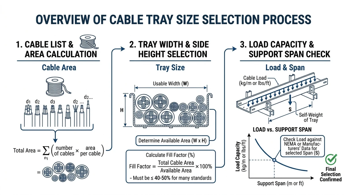
To size a cable tray, first add the outside diameters of all cables on the route and apply a 40–50% fill ratio, then pick the next standard width (typically 150, 300, 450, or 600 mm). Next, check the tray’s load rating (for example, 75–150 kg/m under IEC 61537 test spans) against the total cable weight plus 20–30% margin for future additions.
Step 1 – List Cables and Estimate Fill Area
Before deciding what size cable tray you need, you must know how much cable cross‑sectional area you are carrying and what fill ratio is acceptable. Tray width is effectively the required cable area divided by the allowable fill, plus margin for future circuits.
1. Make a Simple Cable Inventory
Create a short table or spreadsheet, one row per cable type on the route with quantity, service, outside diameter, and planned future spares. Use catalogue data or measure samples; for flat or composite assemblies, use the manufacturer’s “equivalent diameter” so all entries can be treated as round cables in the next step.
2. Convert Diameters to Area
For round cables, approximate the cross‑sectional area as:
Area per cable ≈ π × (D/2)²
Example:
D = 18 mm → area ≈ 3.14 × 9² ≈ 254 mm²
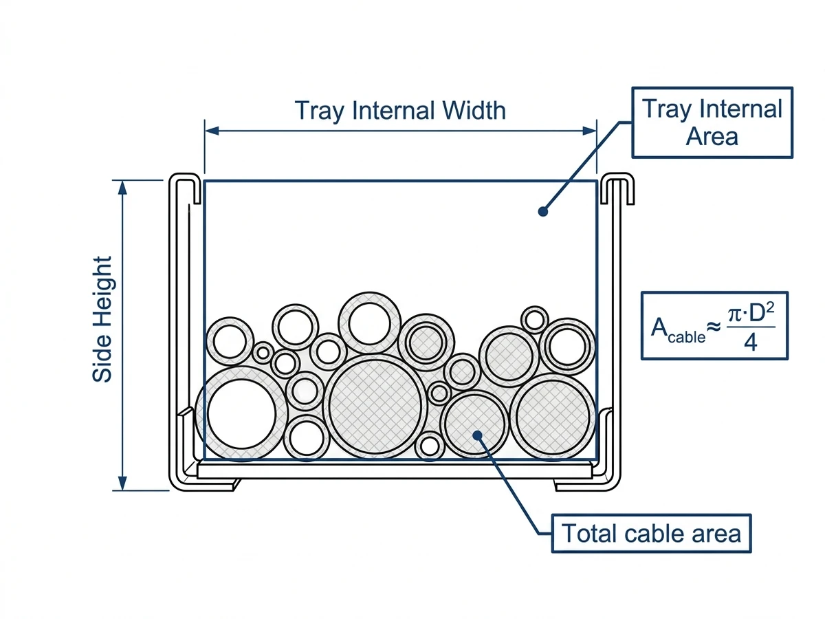
Multiply by the number of cables to get area per type, then sum to obtain total cable area on the tray. This represents the material actually occupied by cables, not the voids between them, which is why the tray’s internal area must be larger than this number.
3. Apply a Fill Ratio and Margin
Typical working fill is 30–45% of the internal tray cross‑section to manage heat, derating, and access. For example, if total cable area = 20 000 mm² and design fill = 40%, required internal area ≈ 20 000 ÷ 0.40 ≈ 50 000 mm², then add 10–25% extra area for future cables depending on how stable the installation is expected to be.
Figure 1. Cable tray cross-section illustrating internal width, side height and how total cable area relates to the chosen fill percentage for initial sizing.
Step 2 – Match Fill and Loading to a Standard Tray Size
Once you know the cable bundle area, you convert it to a standard cable tray width and depth that satisfies both fill and load. The governing checks are:
Fill ratio: typically ≤40–45% on day one
Allowable uniformly distributed load (UDL): kg/m at your chosen span
Convert Cable Bundle to Required Internal Width
Estimate the “packed” cable belt width from the total cable area by dividing by an assumed effective depth of 50–75 mm, then divide by your target fill. If that calculation gives an effective width of 525 mm at 40% fill, you would choose the next standard size, usually a 600 mm tray, and if you are within 5–10% of a breakpoint it is prudent to step up one width for future margin.
Pick an Appropriate Tray Depth
Tray depth mainly helps control stacking and bend radius rather than total area: 50–75 mm depth is usually enough for control and data, while LV power cables ≥50 mm diameter often need 75–100 mm depth to maintain bend radius (commonly ≥8×D) at fittings, especially where frequent additions or re‑routing are expected.
Check Load Class Against Your Calculated kg/m
Sum cable weights per meter (for example, 18 kg/m power + 7 kg/m control = 25 kg/m), apply a factor of about 1.2–1.3 for future additions, and compare the result with catalog UDL at your chosen span (for example, 75 kg/m at 3.0 m under IEC 61537). If the design load exceeds about 60–70% of the rated load, either increase tray load class or shorten the support span so that both fill and structural capacity are satisfactory.
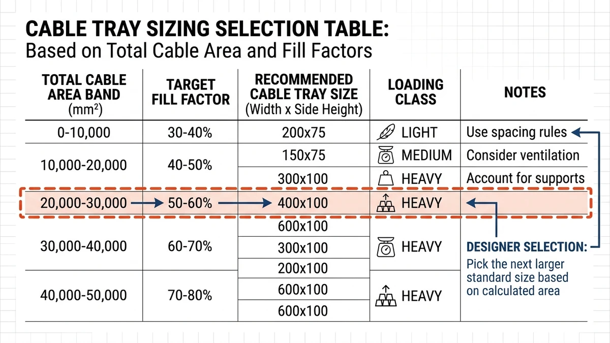
Figure 2. Mapping of required internal cable area and target fill factor to common standard cable tray widths and side heights for different loading levels.
Step 3 – Adjust for Application and Installation Conditions
A tray size that works in one environment may be marginal in another. After initial sizing from fill and load, adjust for location, access, and routing constraints.
Environment and Protection Level
Outdoor, corrosive, or dusty environments often justify wider and sometimes heavier trays: extra width (+10–20%) simplifies drip loops and pulling in cold conditions, heavier‑gauge or coated trays increase self‑weight and can reduce available capacity at a given span, and covers or fire barriers effectively reduce usable height so a lower working fill (around 30–40%) is often more realistic.
Routing, Access, and Supports
Long spans or elevated pipe racks may favor several narrower trays instead of one wide tray for handling and deflection control, while maintenance areas benefit from avoiding “just enough” width so cables can be moved without damage. On vertical runs and risers, many designers limit fill to about 40% and may select the next tray width up to keep pulling forces and side access reasonable.
In Xinma’s industrial deployments, revisiting span and tray class after route optimization has often prevented on‑site changes, particularly at long outdoor runs where support locations shift during steel coordination.
[Expert Insight]
– When trays share supports with process pipes, confirm the chosen width still fits between structural elements with at least 25–50 mm installation tolerance.
– For multi‑tier tray stacks, size from the heaviest lower tier upward so support options remain workable for all levels.
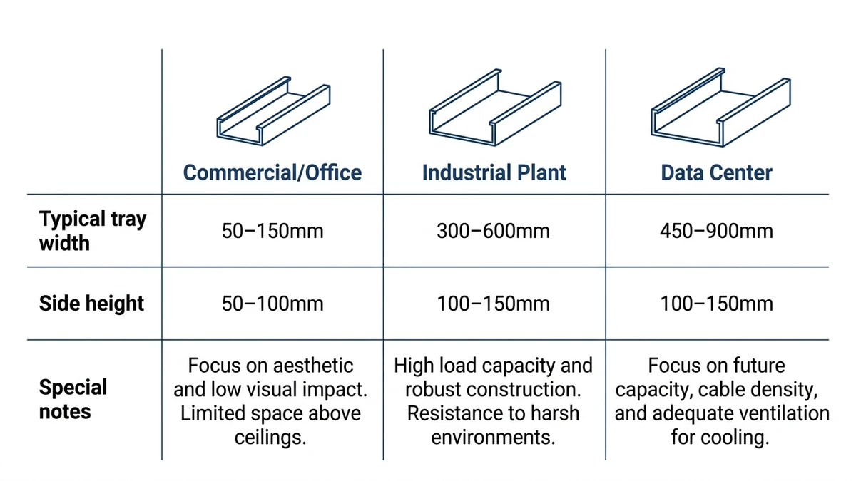
Figure 3. Application matrix showing typical cable tray width and side height ranges for commercial branches, industrial corridors and data center cabling routes.
Allowance for Future Cables, Support Spans, and Accessories
Sizing only for day‑one cables typically underestimates the tray width you will actually need. A realistic design reserves spare fill and verifies that tray strength, support spans, and accessories remain adequate if that spare space is eventually used.
Engineering Margin for Future Cables
For relatively static power systems, many designers keep ultimate fill within about 60–70% of internal cross‑section, while light control and instrumentation can sometimes go higher if derating and segregation rules are satisfied. Confirm that adding several kg/m of cable in the future still keeps total load under the tray’s rated UDL and recognize that ampacity derating depends strongly on the number of current‑carrying conductors in proximity, so a modest increase in width or depth can improve cooling.
Rule of thumb: if day‑one fill is already above about 60%, it is usually better to step up one tray size than to assume future circuits can be squeezed in later.
Support Span and Deflection
Support spacing (often 1.5–3.0 m indoors, sometimes up to 4.0 m outdoors if rated) directly affects allowable load and midspan deflection. Check deflection at ultimate load (current plus future cables and covers) against project limits such as L/200; if future loading brings you close to the tray’s class rating, either reduce span or select a higher load class so the installed system does not approach visible or functional deflection limits.
Accessories, Fittings, and Add‑Ons
Covers, dividers, tees, reducers, and vertical drops add weight and can concentrate loads at fittings and connections, often requiring shorter spans or extra brackets. Drop‑outs, bonding jumpers, and earth clamps also need edge clearance; if the tray is sized too tightly, these accessories can force non‑compliant bend radii and make cable handling difficult, so always validate sizing against a “fully accessorized” condition.
Cable Tray Size, Type, and System Coordination
Tray size is only one dimension of a cable management system. Tray type and how it integrates with busway, supports, and fittings will change the optimal width and depth.
Ladder vs. Perforated vs. Solid for a Given Size
For the same nominal size, ladder trays usually carry higher loads and achieve longer spans, perforated trays offer continuous support for smaller cables at moderate load, and solid‑bottom trays improve containment and EMC but tend to need lower fill or larger sizes due to heat build‑up. At a typical 300 mm width, ladder trays often tolerate roughly 20–40% higher UDL than perforated trays at the same span because more steel is concentrated in the side rails.
Use when / avoid when / check before specifying:
Ladder tray: use for heavier power loads and spans ≥2.5 m, avoid when many small flexible cables need continuous support, and check rung spacing against minimum cable size.
Perforated tray: use for mixed control and light power, avoid for very heavy single‑core power on long spans without confirming load class, and check hole patterns for tie‑wraps and clamps.
Solid‑bottom tray: use for shielding and cleanliness, avoid in hot environments unless derating is calculated, and consider that covers and limited ventilation usually demand lower working fill.
[Expert Insight]
– In Xinma’s testing, changing from perforated to ladder tray at the same width and span has reduced midspan deflection by roughly 25–35% at equivalent load, giving more capacity for later cables.
– Underspecified stiffness often first appears as difficulty aligning fittings at joints due to sag, rather than immediate structural failure.
Coordination with Busway and Major Equipment
Near busway tap‑off points, tray width must allow for cable bends from tap boxes while respecting minimum bend radius, which may require a wider or flared section for a short distance. Similarly, where trays drop to MCCs or switchboards, gland plate clearances can force transitions from a wider upstream tray to a narrower one, so a coordinated layout will standardize a small set of tray widths and use reducers and fittings locally rather than many unique sizes.
Standards, Testing, and Verification for Cable Tray Sizing
To validate your chosen cable tray size and span, use manufacturer test data referenced to recognized standards. For metallic trays, IEC 61537 is a common basis for load testing and deflection limits in many markets. The publication is available through the IEC webstore: IEC 61537 publication page
What to Check in Standards and Catalog Data
When reviewing data, confirm UDL ratings at your intended support span, review deflection information at different percentages of test load, and check any stated limits on fill or separation between power, control, and data cables. IEC 61537 clauses on load testing define test setups and deflection criteria so trays from different suppliers can be benchmarked consistently at the same span and load.
Experience from Field Deployments
Across industrial and commercial projects, trays sized purely by nominal width without span‑specific load checks often require extra supports during construction, increasing steel and labor, while projects that define a “design load per tray route” in kg/m and size trays specifically to that figure see fewer late changes and less oversizing. Treating cable tray size as a calculated parameter tied to area, load, and span improves both technical performance and cost control.
How Xinma Helps Turn Sizing Rules into a Buildable Tray Layout
Cable fill, load class, support spans, and derating interact quickly once you move from a cable schedule to real routes. Xinma’s role is to turn those calculations into a coordinated cable management system that installers can build and inspectors can verify.
Xinma’s engineers typically start from your cable list, one‑line, and preliminary routes, then check tray width and depth against target fill and future spare, verify structural ratings against calculated distributed loads plus 20–30% margin, align support spacing and fittings with IEC/NEMA deflection criteria, and flag routes where ampacity derating is sensitive to coverage, stacking, or proximity to heat sources. On several large industrial projects, early review of tray size, type, and span has reduced the number of support variations by more than a third.
If you are defining a new system or revising an existing one, Xinma can work from your routes to propose standardized tray widths and types, compatible covers and fittings, and support spacing matched to design loads, turning “what size cable tray do I need?” into a consistent, drawing‑ready specification instead of isolated catalog choices.
This article has been updated with explicit source and procurement checks so engineering, EPC, and purchasing teams can verify the recommendations instead of relying only on generic product descriptions. For project use, treat the table below as a starting evidence map and confirm the final requirements against local codes, consultant drawings, and supplier submittals.
Use this source to verify standards, product scope, installation assumptions, or supplier evidence before final specification.
Buyer Verification Checklist
Request drawings that show tray width, depth, side rail profile, bend radius, fittings, and support spacing.
Ask for load tables or engineering assumptions that state test span, load class, and deflection criteria.
Confirm material grade, surface finish, coating method, and corrosion exposure assumptions before comparing prices.
Check whether accessories such as covers, couplers, reducers, clamps, grounding jumpers, and brackets are included.
For EPC or export orders, review packaging, labeling, inspection records, and drawing revision control before shipment.
Frequently Asked Questions
How do I calculate cable tray width from a cable schedule?
Add the cross‑sectional area of every cable on the route, divide by your target fill ratio (for example, 0.4), and then select the next higher standard tray width whose internal cross‑section meets or exceeds that required area.
What support spacing should I use for cable trays?
Choose support spacing based on the tray’s tested span in the catalog, typically 1.5–3.0 m, and verify that deflection at your combined cable and accessory load remains within project limits such as L/200 of the span.
Can I run power and control cables in the same cable tray?
You can often route power and control together if you respect minimum separation distances, use dividers where needed, and keep noise‑sensitive circuits away from high‑current or switching conductors to reduce electromagnetic interference.
How much spare capacity should I leave in a cable tray?
A common approach is to design day‑one fill around 40% and allow future additions up to about 60–70% for power and slightly higher for light control cables, as long as structural load limits and ampacity derating remain acceptable.
When should I choose ladder tray instead of perforated tray?
Ladder tray is usually preferred for heavier power cables and longer support spans because it offers higher load capacity and better ventilation, while perforated tray suits mixed smaller cables where continuous support is more important than maximum span.
Do covered cable trays need a different sizing approach?
Covered trays typically require either a lower working fill ratio or a larger size because the cover restricts heat dissipation and access, so you should explicitly check ampacity derating and maintenance needs before finalizing dimensions.
Kevin Zheng
Kevin Zheng is a manager linked to Shanghai Xinma Busway & Cable Tray Co., Ltd. He writes technical content on cable tray systems, installation practice, sizing logic, load classes, and related standards for industrial and infrastructure applications.