Quick Answer: The Main Factors Behind Cable Tray Load Capacity
Cable tray load capacity is mainly governed by tray type and geometry, material properties, span length between supports, and installation environment. Mechanically, deflection and yield strength limit how many kilograms per meter (kg/m) the tray can carry at a given span. Standards such as IEC 61537 define test methods, load classes (often 50–200 kg/m over 2–3 m spans), and deflection limits that manufacturers use to rate their systems.
How Tray Type, Geometry, and Material Shape Load Capacity
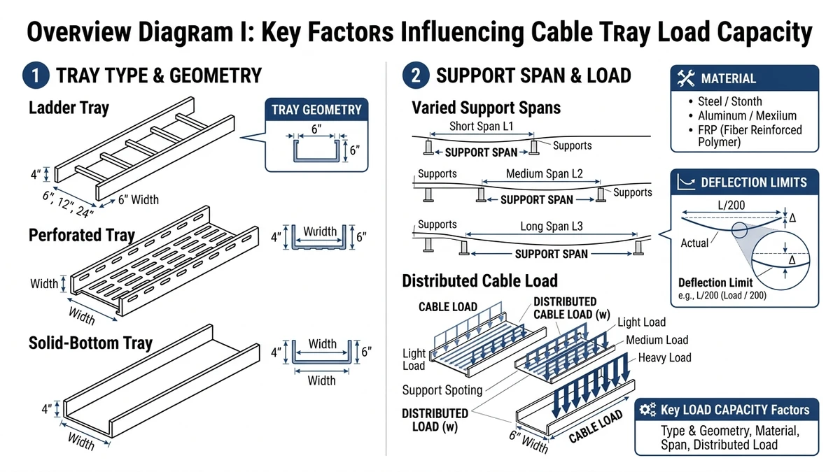
Cable tray load capacity is set by basic beam mechanics: how the cross‑section resists bending and how stiff the system is over the support span. Tray type, geometry, and material control these properties, so the same 300 mm‑wide cable route can safely carry 50 kg/m or 200 kg/m depending on those choices.
Tray Type and Structural Action
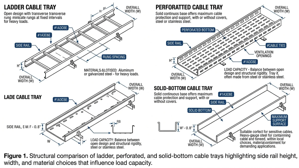
Ladder trays use two longitudinal side rails and rungs; their load capacity mainly scales with rail height and thickness, so a 100 mm‑deep ladder tray at 3.0 m span may carry around 150–200 kg/m, while a 60 mm‑deep tray at the same span may be limited to about 75–100 kg/m. Perforated and solid‑bottom trays have shallower, less efficient sections and are typically rated for lower loads or shorter spans, while wire mesh trays share load among many wires but usually fall in the 30–75 kg/m range or need shorter spans. In a continuous route, the section with the lowest rating at its actual span governs system capacity, so mixing types requires checking each section’s load class and support spacing.
Geometry: Depth, Width, and Side Rail Profile
Depth (tray height) has the strongest effect on bending strength, which increases roughly with the square of depth, so increasing side rail height from 75 mm to 125 mm can nearly double allowable load or permit span growth from about 2.0 m to 3.0 m at similar load. Wider trays carry more cables but generate higher bending stress, so a 600 mm‑wide tray usually needs substantially higher section modulus than a 300 mm tray to support the same kg/m at the same span. Folded flanges, return lips, and box‑like edge profiles can lift stiffness by 20–40% between trays of the same nominal depth, often more efficiently than simply increasing sheet thickness; more detail is outlined in the cable tray dimensions and stiffness overview.
Material: Strength, Stiffness, and Long‑Term Behavior
Steel (carbon or stainless) has high modulus (~200 000 MPa) and yield strength (~235–350 MPa), so it offers high stiffness and tends to control deflection well at typical spans, which is why many heavy‑duty IEC 61537 and NEMA VE 1 systems are steel. Aluminum’s lower modulus (~70 000 MPa) means around three times the deflection of steel at the same geometry and load, so aluminum trays are often deeper or thicker, and FRP/GRP trays generally need shorter spans (around 1.5–2.5 m) or lower working loads because of lower stiffness and creep under sustained load. Thermal expansion is also higher for aluminum and FRP (about 23 µm/m·°C) than for steel (~12 µm/m·°C), so long runs require expansion details; comparative implications by material are summarized in the ladder cable tray selection notes.
Figure 1. Structural comparison of ladder, perforated, and solid-bottom cable trays highlighting side rail height, width, and material choices that influence load capacity.
Span, Supports, and Deflection Limits in Real Installations
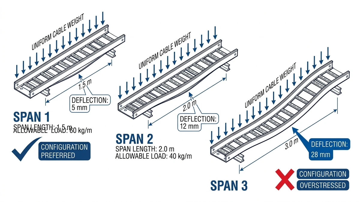
Span and support spacing determine how a cable tray behaves under load. For a given tray profile, longer spans increase deflection and reduce allowable uniformly distributed load (UDL), and on real sites support spacing often drives tray size more than catalog load class.
How Span Changes Capacity
Cable tray ratings are always tied to a specific test span, typically 2.0–3.0 m under IEC 61537 or NEMA VE 1, and midspan deflection grows roughly with the cube of span length. Increasing span from 2.0 m to 3.0 m can raise deflection by about 3–4 times at the same UDL, so allowable working load must be reduced or the tray must be stiffened. In practice, spans of about 1.5–2.0 m are common for light indoor runs, 2.0–3.0 m for standard industrial routes, and 1.5–2.5 m where loads or seismic demands are higher; if a tray is rated only 100 kg/m at 3.0 m but you require 150 kg/m, either shorten the span or select a stiffer tray section, as heavier hangers do not increase tray capacity.
Deflection Limits and Serviceability
Standards often use deflection limits such as L/200 or L/250 to control serviceability, meaning a 3.0 m span limited to L/200 must not deflect more than 15 mm at working load. If tested or calculated deflection exceeds that value, the span, tray section, or working load must be adjusted even if material strength is not exceeded. Excessive deflection reduces side‑rail freeboard, promotes ponding in solid‑bottom trays, and increases vibration and joint movement, which can contribute to fatigue or maintenance issues over time.
[Expert Insight]
– In retrofit projects, noticeable sagging usually reflects spans extended 0.5–1.0 m beyond the tested value rather than overload alone.
– Reducing span from 3.0 m to 2.0 m on existing steel ladder trays often cuts midspan deflection by more than half without changing tray type.
Practical Field Checklist
When laying out supports:
Confirm the manufacturer’s load rating at the exact span you intend; changing from 2.0 m to 3.0 m can alter capacity by 30–50%.
Set a design deflection limit (for example L/200) and confirm deflection at working load using tables or simple beam calculations.
Include cable weight, tray self‑weight, covers, environmental loads, and at least 20–30% future margin in the line load.
Shorten spans near heavy terminations, vertical drops, and major direction changes.
In seismic or vibration‑sensitive zones, use shorter spans and bracing to control dynamic deflection instead of relying only on heavier tray profiles.
Further examples of how support patterns influence tray behavior are illustrated in the cable tray support design article.
Figure 2. Illustration of identical cable tray sections at different support spans demonstrating how longer spans increase deflection and reduce allowable load.
Standards, Testing, and How to Read Load Tables
Cable tray load capacity in catalogs comes from standardized tests that apply a known load over a defined span with an allowable deflection. Understanding these test conditions is essential before using any load table for design.
What the Main Standards Actually Govern
IEC 61537 and its national adoptions (such as BS EN 61537) define requirements and mechanical test methods for metallic cable tray and ladder systems, including test spans, deflection limits, and some durability checks (see IEC webstore: IEC 61537 publication page). NEMA VE 1 covers similar topics for metal cable tray systems in North America, while BS EN 50085 addresses trunking and ducting systems, and GB 31251 sets test and classification rules in China. Typical mechanical tests place a uniformly distributed load of about 100–300 kg/m over a 2.0–3.0 m span and limit midspan deflection to values such as L/200, so a 3 000 mm span must not deflect more than about 15 mm at its rated working load.
How Laboratory Tests Translate to Catalog Load Tables
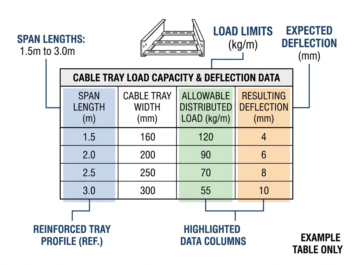
Catalog load tables generally list tray type and width, test span, working load (kg/m), and associated midspan deflection, and these values are valid only for that specific span and configuration. If you increase span beyond the test value, the same working load no longer complies with the deflection and strength criteria, and new calculations or ratings are needed. For safe design, your actual support spacing must not exceed the listed span, your combined cable, cover, and tray self‑weight must stay below the working load with margin, and you should not extrapolate IEC or NEMA load classes to longer spans at unchanged kg/m ratings.
Step‑by‑Step: Reading a Load Table Correctly
Step 1 – Fix your design span
Determine support spacing from the building structure or support steel, and only use table entries with test spans at or below that spacing.
Step 2 – Calculate cable load
Sum cable masses (kg/m) at target fill, then add 20–30% growth allowance plus cover or accessory weight; for example, 55 kg/m of cables becomes about 72 kg/m after a 30% margin before adding covers.
Step 3 – Compare to working load
Ensure cables + covers + tray self‑weight do not exceed roughly 70–80% of the catalog working load so that installation tolerances, uneven loading, and environmental effects are covered.
Step 4 – Check deflection
Compare catalog deflection to your limit (for example L/200 or L/250), tightening criteria for sensitive systems such as fiber‑optic cables where excessive sag may affect bending radius.
Design takeaway: treat load tables as sets of span–load–deflection combinations and keep all three aligned with your project conditions.
Figure 3. Example cable tray load and deflection table with span, allowable load, and deflection columns highlighted to guide engineers in using manufacturer data correctly.
Applying Load Capacity Factors to Project Design and Purchasing
Turning load capacity into a project specification means linking tray class, span, and width to realistic installed loads with margin, so that engineering intent is preserved through procurement and installation.
Step 1 – Define Realistic Design Loads
Estimate per‑meter load for each route by summing current cable weights, then adding allowances such as 20–30% for future cables and 5–10% for accessories and maintenance activity. As an example, 40 kg/m of power cables plus 15 kg/m of control cables becomes a design load of about 75 kg/m after adding common contingencies on a 300 mm‑wide tray. If you are unsure how to obtain cable masses or apply margins, the cable tray size calculation guide outlines typical data sources and steps.
Step 2 – Select Load Class and Span Together
Using IEC 61537 or NEMA VE 1 data, compare allowable loads and deflections at candidate spans (for example 2.0 m, 2.5 m, 3.0 m) for your tray type and width. If your 75 kg/m design load exceeds capacity at 3.0 m but is acceptable at 2.0 m, either retain the tray profile and tighten support spacing or choose a higher load class or deeper profile that meets 75 kg/m at 3.0 m. Because tray profile and allowable span are coupled, procurement should not substitute one without re‑checking load and deflection for the specific project conditions.
Step 3 – Check Width, Fill, and Future Growth
Select tray width from cable count and permissible fill (often 40–60% initial fill for power trays), then verify that the needed load class is available at that width. Recalculate line load using the heaviest likely cable mix and any planned upgrades so that the tray rating at actual support spacing exceeds both current and forecast loads with agreed margin; for instance, if you expect an extra 20 kg/m of future cables, ensure catalog capacities comfortably cover today’s load plus that increase.
Step 4 – Align Engineering Specs and Procurement Data
Specify quantitative performance, such as “Tray shall support ≥100 kg/m uniformly distributed load at 3.0 m span with maximum deflection ≤L/200, tested per IEC 61537,” and require supporting manufacturer load tables. During bid evaluation, treat changes to span, duty class, material, or tray type as design changes needing verification, rather than assuming products labeled similarly are interchangeable.
This approach keeps load capacity as a verifiable criterion from design through tendering and installation.
How Xinma Helps Coordinate Loading, Supports, and Fittings in Cable Tray Design
Cable tray load capacity decisions affect support spacing, fitting placement, cable fill, and sometimes thermal performance, so the tray system is best engineered as a continuous structure instead of isolated items. For instance, a 300 mm‑wide ladder tray carrying about 80 kg/m of cables may require spans reduced from 3.0 m to roughly 2.0 m to maintain an L/200 deflection limit unless a higher‑stiffness profile is chosen. Added covers typically increase self‑weight by 3–6 kg/m and must be included in vertical and seismic checks, while large fittings such as 600 mm tees or elbows often dictate hanger locations and may need extra supports within about 300–500 mm of each branch or direction change to control local deflection and joint stress.
Xinma’s technical team can help verify that selected tray models meet required load and deflection at specified spans using IEC 61537 or NEMA VE 1 data, recommend support hardware and spacing where hanger capacity or accessories change, and confirm that elbows, tees, reducers, and vertical drops maintain both load capacity and minimum bend radii for LV, MV, and data cables. They can also review thermal and ampacity impacts when ventilation style, tray depth, or covers change for EMC or fire‑protection reasons, and coordinate tray and busway loads and clearances in shared corridors as outlined in the busway system overview; the cable tray systems guide summarizes broader system options and configurations.
How this page differs from related XMQJ guides
This page focuses on its stated search intent. For product-level selection, start from Xinma Cable Tray Systems and then compare the related engineering guides linked above.
Engineering Evidence and Verification Sources
This article has been updated with explicit source and procurement checks so engineering, EPC, and purchasing teams can verify the recommendations instead of relying only on generic product descriptions. For project use, treat the table below as a starting evidence map and confirm the final requirements against local codes, consultant drawings, and supplier submittals.
Use this source to verify standards, product scope, installation assumptions, or supplier evidence before final specification.
Buyer Verification Checklist
Request drawings that show tray width, depth, side rail profile, bend radius, fittings, and support spacing.
Ask for load tables or engineering assumptions that state test span, load class, and deflection criteria.
Confirm material grade, surface finish, coating method, and corrosion exposure assumptions before comparing prices.
Check whether accessories such as covers, couplers, reducers, clamps, grounding jumpers, and brackets are included.
For EPC or export orders, review packaging, labeling, inspection records, and drawing revision control before shipment.
Frequently Asked Questions
How do I estimate cable tray load capacity from cable data?
Add the mass per meter of every cable planned in the tray, include a growth allowance (often 20–30%), and compare the total kg/m against the manufacturer’s rated working load at your intended span, ensuring a further safety margin where seismic or outdoor loads are expected.
Can I increase cable tray load capacity just by adding more supports?
Reducing span by adding supports usually increases allowable load and reduces deflection, but the tray’s tested rating at that shorter span must still be checked rather than assumed, particularly for aluminum and FRP systems where stiffness is lower.
When should I choose ladder tray instead of perforated or wire mesh?
Ladder tray is generally preferred for higher cable masses, longer spans (around 3.0 m), and routes with frequent vertical drops, while perforated or wire mesh trays can be suitable for lighter control and data runs with shorter spacing and lower mechanical loads.
How does adding tray covers affect load and support spacing?
Covers increase self‑weight by several kilograms per meter and can raise wind, snow, or ice loads outdoors, so load checks should be redone with the new line load, and in some cases support spacing needs to be reduced or hanger sizes increased.
Are catalog load tables enough to approve a cable tray design?
Catalog tables provide essential starting data, but a complete design also checks real support spacing, combined cable and accessory weight, deflection limits, environmental loads, and any additional project requirements such as seismic or fire performance.
What happens if I exceed the specified deflection limit on a cable tray span?
If deflection goes beyond the chosen limit (such as L/200), cable bending radius, freeboard, and joint stresses can deteriorate over time, so engineers typically respond by shortening the span, upgrading to a stiffer tray profile, or reducing the installed cable load.
Kevin Zheng
Kevin Zheng is a manager linked to Shanghai Xinma Busway & Cable Tray Co., Ltd. He writes technical content on cable tray systems, installation practice, sizing logic, load classes, and related standards for industrial and infrastructure applications.