Address
304 North Cardinal St.
Dorchester Center, MA 02124
Work Hours
Monday to Friday: 7AM - 7PM
Weekend: 10AM - 5PM
Address
304 North Cardinal St.
Dorchester Center, MA 02124
Work Hours
Monday to Friday: 7AM - 7PM
Weekend: 10AM - 5PM
Get premium quality cable management systems directly from the manufacturer.
Fill out the form below to receive our catalog and pricing.
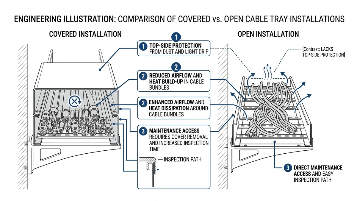
Cable tray covers change three design conditions at once: protection, heat dissipation, and maintenance access. Under IEC 61537, a cover is not just an accessory; it changes what reaches the cables, how heat leaves the bundle, and how quickly technicians can inspect or modify the run. In practice, solid steel covers can improve protection against dust, debris, and drips, but they can also raise cable temperature by several °C and slow access along each tray section.
For specifiers, the question is not whether a cover is “better,” but whether it solves the main site hazard without creating a bigger thermal, structural, or maintenance penalty elsewhere. IEC 61537 governs cable tray and ladder mechanical requirements, while cable thermal rating still has to be checked at system level using the applicable cable rating method. For reference, see the IEC 61537 publication page.
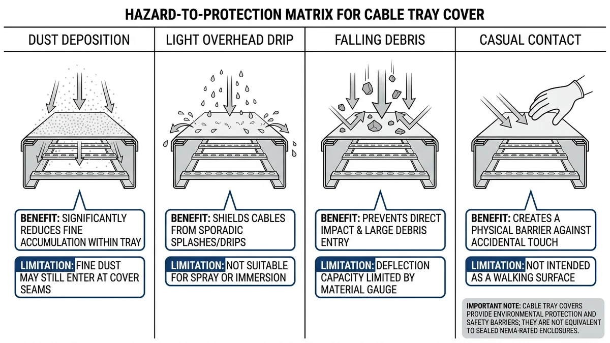
Cable tray covers protect against external exposure, but they do not turn a tray into a sealed enclosure unless the full assembly is designed and tested that way. In most projects, the real benefits are against falling debris, dust, UV exposure, wind-blown contamination, incidental contact, and light splash or dripping water.
A cover should be matched to the actual hazard. Solid covers give the strongest barrier against fallout and sunlight, while ventilated covers mainly block larger debris and preserve more airflow.
| Hazard / exposure | How the cover helps | Typical limit or condition | Design consequence |
|---|---|---|---|
| Falling debris from overhead steel, piping, or ceiling work | Solid covers intercept dropped nuts, scale, concrete dust, and light tools before they strike cable jackets | Most effective for small vertical impact; not a substitute for guards against heavy dropped loads above about 2 kg | Favor covered tray below mezzanines, pipe racks, and retrofit zones with active overhead work |
| Dust and dirt accumulation | Reduces settling on cable surfaces and inside the tray | Useful in cement, mining, woodworking, and warehouse environments with continuous airborne particulates | Cleaning intervals may extend from monthly to quarterly, but inspection becomes slower |
| UV exposure and weathering | Shades polymeric cable jackets from direct sunlight | Most relevant on outdoor runs with multi-year exposure | Helps limit jacket aging and can reduce direct solar heating by several °C |
| Wind-blown debris and leaves | Limits entry of litter and coarse debris | Long outdoor runs above 20 m tend to collect more material | Reduces blockage around cable bundles and lowers cleaning frequency |
| Incidental personnel contact | Adds a barrier against casual touching of cable surfaces | Not equivalent to a touch-safe enclosure under all codes | Useful on walkways and service platforms, but lockout and guarding rules still apply |
| Splash or drip contamination | Blocks vertical drips from process lines or roof leaks | Works for occasional drips, not liquid-tight service | Good below HVAC condensate lines; poor choice for frequent washdown |
| Rodents and birds | Partially deters entry by reducing open access | Depends heavily on splice gaps and open sides | Requires end closures and fit-up discipline if pest exclusion matters |
Cable tray covers usually do not provide a tested ingress protection rating unless the tray-cover assembly is specifically certified as an enclosure system. They also do not prevent internal cable problems such as overload heating, short-circuit damage, or insulation aging from excessive conductor temperature.
Use covers where the dominant risk is external and repetitive. They are a poor substitute for solving internal thermal loading, frequent cable changes, or fast inspection needs.
[Expert Insight]
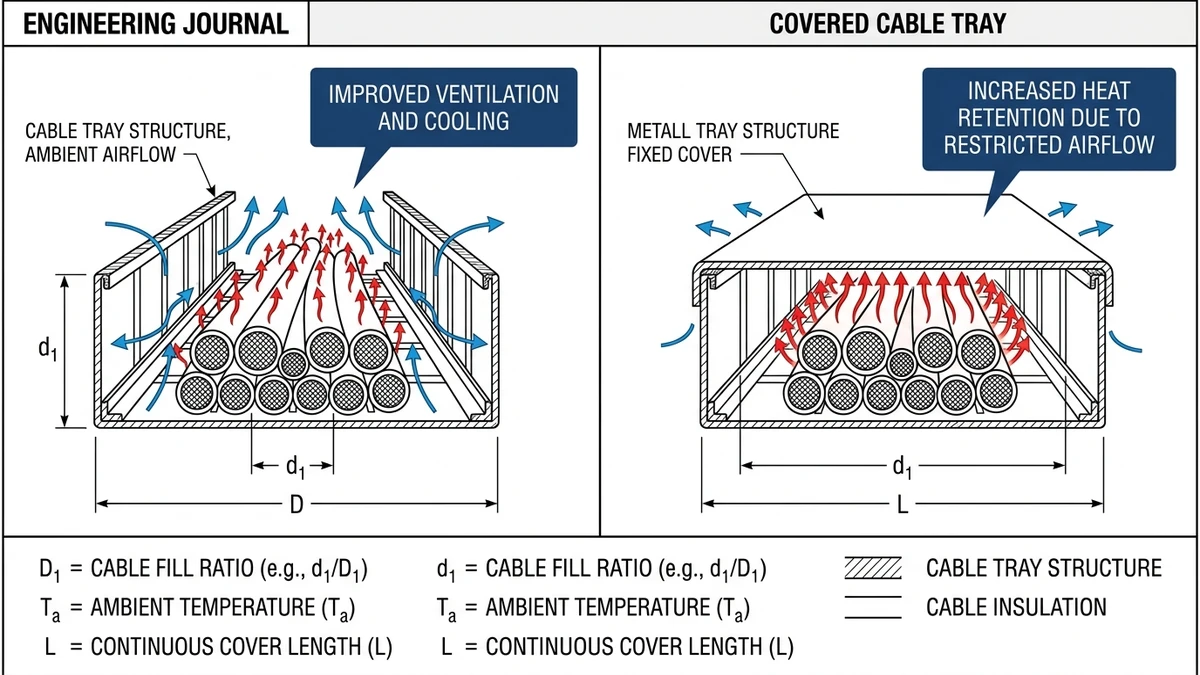
A cable tray cover reduces convective cooling, so it can raise cable temperature and shrink ampacity margin. The effect is usually modest on lightly loaded signal trays, but it matters on power runs with high fill, warm ambient conditions, or limited spacing between circuits.
This is the main trade-off: better environmental protection, less natural ventilation. If covers are added after cable sizing was based on open-tray conditions, the installed system may no longer match the original rating assumptions.
Adding a cover reduces air exchange above the cable bundle and can increase local heat buildup, especially at dense cable clusters or long covered spans. Outdoor metallic covers may also add solar heat gain on exposed routes.
Review load current, conductor temperature rating, tray fill, tray geometry, cover type, ambient temperature, solar exposure, loaded conductor count, spacing, ventilation gap, and covered run length. Thermal performance depends on the combination, not one parameter in isolation.
Use solid covers where debris, dust, or drips are the main hazard and the tray still has thermal margin after review. Avoid long solid-covered runs on high-fill feeders unless the cable rating method confirms acceptable conductor temperature; in many cases, a wider tray, lower fill, ventilated cover, or local shielding is a cleaner solution.
Consider a 600 mm ladder tray carrying several loaded power circuits at about 50% fill in a 45 °C process area. If a solid cover raises cable temperature by only a few °C, that may consume the remaining design margin and make the covered section the thermal worst case.
[Expert Insight]
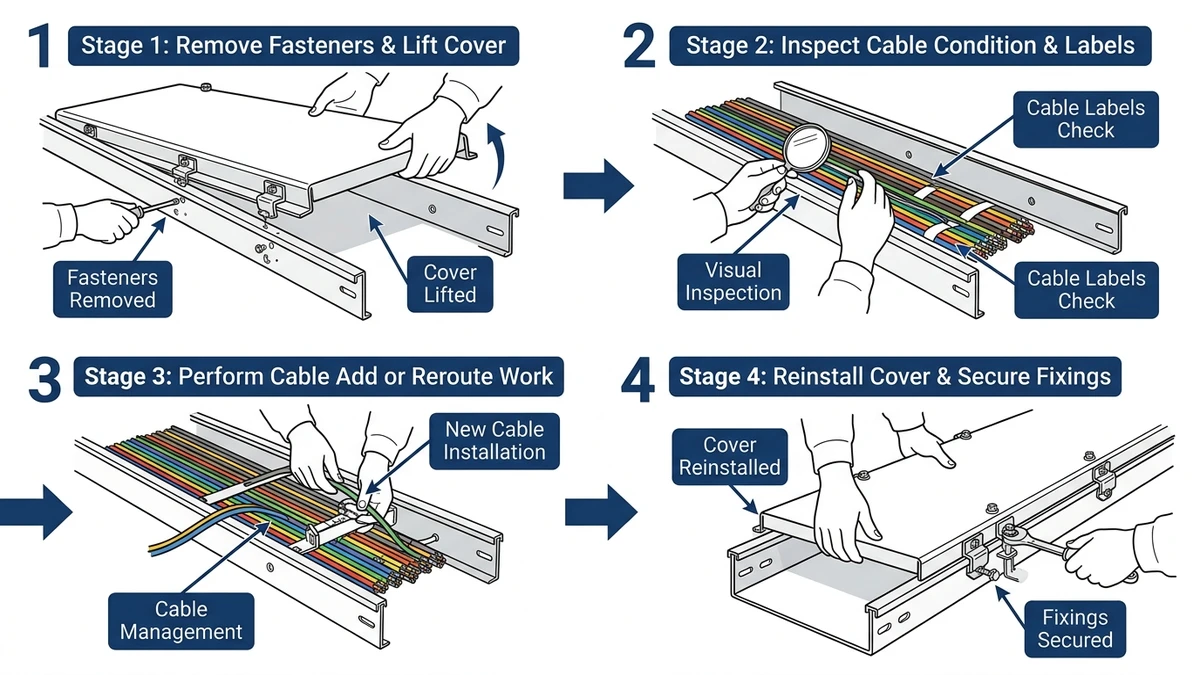
Covered tray improves protection but slows maintenance because inspection, cable additions, testing, and fault tracing all start with cover removal and reinstallation. What looks minor in design review often becomes a labor, clearance, and outage issue in the field.
The practical impact depends on tray location and how often the route changes. Stable feeder paths tolerate covers better than instrumentation, control, or data routes that need regular intervention.
Open tray allows direct viewing of routing, fill, and jacket condition, while covered tray requires overhead removal clearance and handling space for each section. In tight spaces, the available clearance above the tray often determines whether maintenance is routine or disruptive.
Covers are usually acceptable where contamination is the main failure driver and cable changes are rare. Where troubleshooting speed or frequent modifications matter, repeated opening and refastening can become the dominant maintenance penalty.
Covered vs open cable tray is mainly an environmental and thermal choice. Covered tray is stronger against dust, debris, UV, and dripping water, while open tray gives better airflow, faster inspection, and easier cable changes.
The right answer depends on the most credible failure mode on that route: external contamination or internal heat buildup.
| Parameter | Covered cable tray | Open cable tray |
|---|---|---|
| Environmental protection | Better against dust, debris, dripping liquids, and UV | Limited barrier protection |
| Heat dissipation | Lower natural ventilation; thermal review is usually required in warmer or high-fill runs | Better airflow and more ampacity margin |
| Maintenance access | Slower; each intervention needs cover removal or opening | Fast inspection and cable tracing |
| Mechanical loading | Higher dead load; cover mass typically adds about 2-8 kg/m depending on width and material | Lower dead load and simpler support checks |
| Outdoor suitability | Strong option where weathering or falling objects are credible risks | Better only where contamination risk is low and ventilation or drainage is the priority |
| Security and contact limitation | Better resistance to casual interference | Lower barrier to incidental contact |
| Best fit | Dusty process areas, tunnels, rooftops, pipe rack zones | Data halls, indoor service corridors, frequently modified control routes |
Use covered tray when external exposure is likely to shorten cable life, increase cleaning burden, or create avoidable maintenance risk. Use open tray when thermal margin is tight, tray fill may grow over time, or inspection access is operationally important.
Avoid one blanket rule across a mixed route. A 30-100 m run often crosses different exposure zones, so selective coverage usually performs better than continuous cover throughout.
For route planning and tray type coordination, see Xinma’s overview of cable management system options, and where ladder geometry is preferred for ventilation, review the ladder tray configuration page.
Cable tray covers should be specified as part of the system, not added after the main design is complete. Once a cover is introduced, environmental protection, thermal derating, support loading, and maintenance access all need to be checked again.
Good specifications usually define where covers are needed, what type is required, and what consequences must be verified before issue.
Identify the actual hazard zones first, such as outdoor sections, runs below process piping, or dusty plant areas, and specify whether covers are continuous or local. Where dimensions and fill growth are still being developed, cross-check tray sizing assumptions early against tray width and sidewall selection guidance.
A steel cover can add about 3-8 kg/m depending on width and thickness, affecting hanger sizing, support spacing, and seismic review; include that weight in the same support model used for tray support and bracing coordination. Electrically, reduced convection may require derating review, especially on high-fill power trays where a small loss of thermal margin can matter.
Straight sections are usually simple to cover, but bends, tees, reducers, and offsets are where fit-up problems appear. Outdoor runs also need hold-down coordination for wind uplift, so confirm compatibility at bends, tees, and other tray fittings and compare field access assumptions against this practical tray installation guide.
Before final issue, ask whether the cover solves a defined exposure problem without creating a hidden thermal or maintenance penalty elsewhere. That answer is most reliable when tray, cover, supports, and access points are reviewed together rather than as separate details.
Cable tray covers are not neutral accessories. A 0.8-1.5 mm steel cover or a 3-5 mm FRP cover can change dead load, ampacity margin, and intervention time across the cable management system.
Start with the real exposure. If the route is outdoors, under process equipment, or exposed to falling debris, UV, or recurring dust, a cover may materially improve protection; in a clean indoor electrical room, it may add little reliability value.
Confirm whether the cover reduces thermal margin enough to justify derating review. Covered horizontal runs above roughly 40-50% fill deserve closer attention, especially when ambient temperature is around 40 °C or higher and cable loading is already near design current.
Check maintenance and structure together. Covers slow inspection and modifications, and even an added 2-6 kg/m over a long run can affect support spacing, fitting loads, or seismic restraint, so specify them only where the hazard clearly justifies the thermal and access trade-off.
A solid cover is usually the better choice where dust, falling debris, UV exposure, or dripping contamination is the main concern. A ventilated cover is often easier to justify when some protection is needed but cable heat rejection still matters.
They can, because covers usually restrict airflow and increase heat retention around the cable bundle. The effect depends on fill ratio, load current, ambient temperature, and whether the cover is solid or ventilated.
They often work well outdoors where debris, weathering, and sunlight exposure are credible risks. The specification still needs to account for wind uplift, corrosion of fasteners, and possible thermal penalty on sun-exposed runs.
The added load varies with material, width, and thickness, but it is commonly several kilograms per meter rather than negligible weight. That extra dead load should be included in support spacing and restraint checks, especially on wider trays.
They usually make access slower rather than impossible. The real impact depends on clearance above the tray, cover section length, fastening method, and how often the route needs cable changes or troubleshooting.
Not in most standard tray applications. If a project needs enclosure-level sealing, the designer should verify whether the full assembly is tested for that duty rather than assume the cover alone provides it.
