Address
304 North Cardinal St.
Dorchester Center, MA 02124
Work Hours
Monday to Friday: 7AM - 7PM
Weekend: 10AM - 5PM
Address
304 North Cardinal St.
Dorchester Center, MA 02124
Work Hours
Monday to Friday: 7AM - 7PM
Weekend: 10AM - 5PM
Get premium quality cable management systems directly from the manufacturer.
Fill out the form below to receive our catalog and pricing.
Choosing between perforated and solid bottom cable tray comes down to three engineering variables: thermal management, mechanical protection, and load capacity. Neither type is universally superior — the right choice depends on cable type, environment, and the load class required under IEC 61537 (cable management — cable tray systems and cable ladder systems). This article works through each variable directly, using real project data to show where each design earns its place.
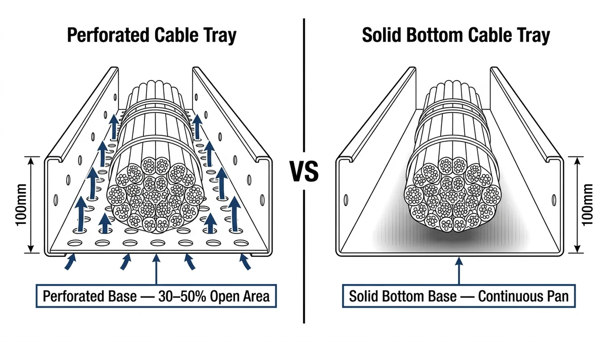
A perforated bottom cable tray has punched openings across its base, typically covering 30–50% of the tray floor area. These openings allow natural airflow around cables, which directly affects ampacity derating. A solid bottom tray has a continuous, unbroken base that encloses cables from below — blocking airflow but shielding cables from dripping liquids, falling debris, and electromagnetic interference.
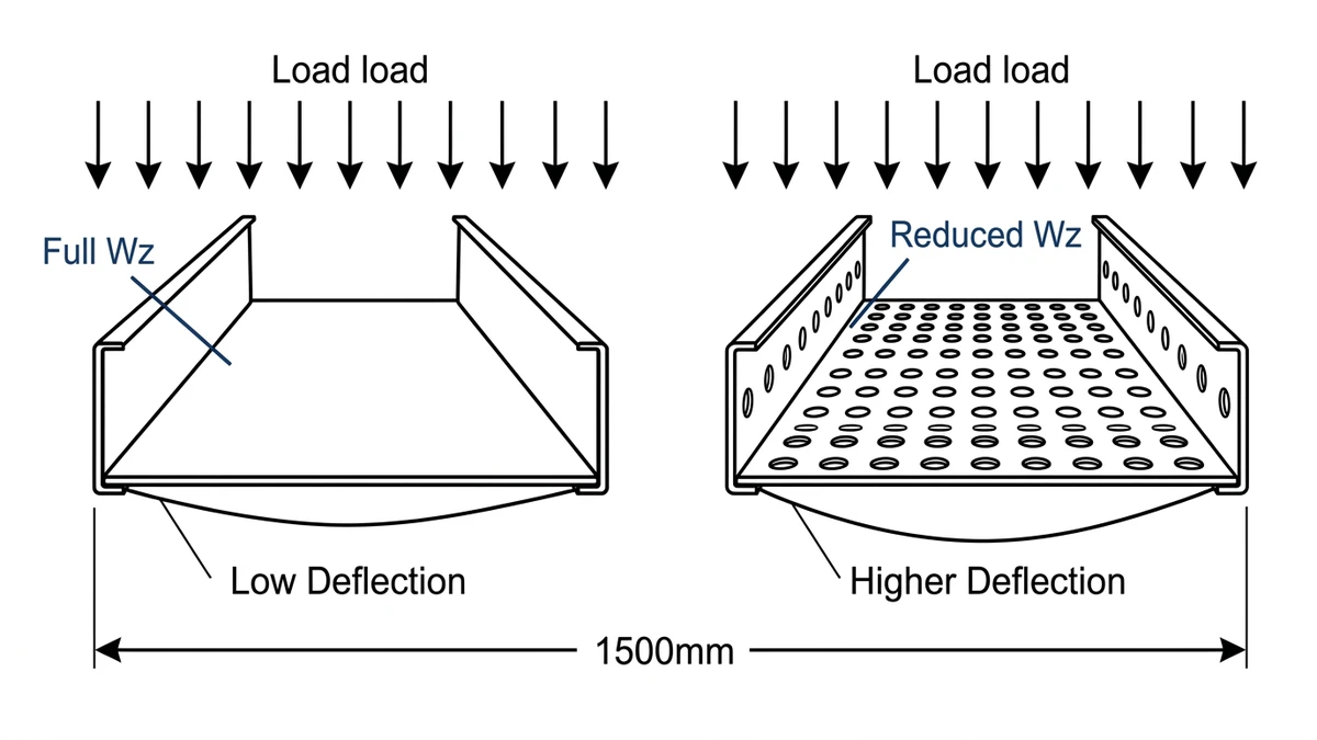
The structural difference is not cosmetic. Solid bottom trays carry a higher section modulus due to the uninterrupted base plate, which generally increases their rated load capacity by 10–20% compared to equivalent perforated trays of the same gauge and width. That margin matters when routing heavy power cables at spans of 1.5 m or greater.
IEC 61537 classifies cable tray load capacity from Class A (50 kg/m) through Class D (200 kg/m), with deflection limits set at L/200 under proof load. Solid bottom trays more consistently achieve Class C and D ratings at standard 1.5 m spans, while perforated trays are more commonly specified at Class A and B for lighter cable management applications.
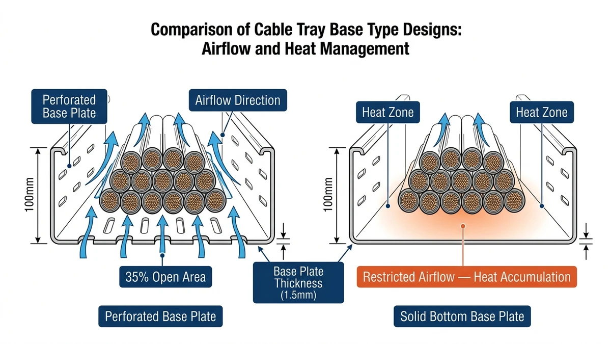
Perforated vs solid bottom cable tray performance diverges most sharply when heat dissipation is the design constraint. Perforated trays allow airflow through the base openings — typically 30–50% open area — which directly supports ampacity ratings for bundled cables. Solid bottom trays trap heat beneath the cable bundle, which can force engineers to apply derating factors under IEC 60364-5-52 (electrical installations — selection and erection of electrical equipment).
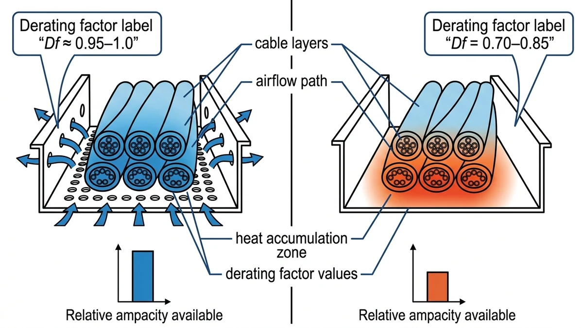
When cables are grouped in a tray, mutual heating reduces each cable’s current-carrying capacity. A perforated tray with ≥ 30% open area is treated similarly to a cable ladder for derating purposes — the airflow path prevents heat accumulation at the tray floor. In a 2023 industrial plant project in Guangdong (12,000 m² facility, 480 power cables routed across three floors), switching from solid to perforated trays in the main cable routing corridors reduced the required derating factor from 0.65 to 0.79. That shift allowed engineers to use a smaller conductor cross-section, cutting cable material costs by approximately 14%.
Solid bottom trays act as a partial thermal barrier. Heat generated by cables on the lower layer has no downward escape path, raising the ambient temperature within the bundle. This effect compounds with fill ratio — at 40% fill, the temperature differential between perforated and solid bottom trays can reach 8–12°C under continuous full-load conditions.
In cable tunnels, basement cable rooms, or enclosed riser shafts, the tray type interacts directly with the room’s ventilation system. Perforated trays allow passive convection to carry heat away from cable surfaces, reducing reliance on forced-air cooling. Solid bottom trays in the same environment require either increased mechanical ventilation capacity or a reduced cable fill ratio — typically capped at 30% versus 40% for perforated — to maintain safe operating temperatures.
For outdoor installations exposed to direct solar radiation, solid bottom trays provide a measurable shielding benefit. Surface temperature measurements on unshielded perforated trays in direct sun have recorded tray floor temperatures up to 15°C above ambient, partially offsetting the ventilation advantage in high-irradiance climates.
[Expert Insight]
– Ampacity derating in grouped cable installations is governed by IEC 60364-5-52, Table B.52.17 — the correction factors differ meaningfully between open (perforated/ladder) and enclosed (solid) tray configurations.
– At fill ratios above 40%, solid bottom trays in enclosed spaces can require conductor upsizing by one or two cross-section steps to maintain the same current rating — a cost that compounds across long runs.
– Passive convection through perforated bases is most effective when tray runs are oriented horizontally with unobstructed airspace below; vertical runs or trays installed tight against ceilings see reduced benefit.
– In data centers with hot-aisle/cold-aisle containment, perforated trays above raised floors allow cold air to reach cable bundles directly, which is a meaningful thermal management advantage at rack densities above 8 kW/rack.
Perforated and solid bottom cable trays share the same structural framework — side rails, cross members, and mounting hardware — so their load ratings under IEC 61537 are largely equivalent when comparing the same material gauge and span. The real difference shows up in how each tray behaves under combined mechanical and thermal stress over time, and in how engineers respond to the environments each type is typically deployed in.
A standard 500 mm wide perforated steel tray spanning 1.5 m typically carries 75–100 kg/m without exceeding the L/200 midspan deflection limit — meaning a 1,500 mm span allows no more than 7.5 mm of sag under full load. Solid bottom trays of identical dimensions and steel thickness perform within the same deflection envelope. However, because solid trays are often specified in environments with heavier cable fills — power cables, armored cables — engineers frequently select a heavier gauge: 1.5 mm versus 1.2 mm. That increases the tray’s self-weight by roughly 15–20% and must be factored into support structure calculations.
In a 2023 petrochemical plant expansion in Shandong Province (approximately 4,200 m of tray installed), solid bottom trays rated at 150 kg/m were installed on 1.2 m spans to support 35 mm² armored power cables. The shorter span was chosen specifically to keep deflection under 6 mm, preventing cable jacket abrasion at tray edges — a failure mode that had caused insulation damage in an earlier installation using 1.8 m spans.
Perforated trays in the same facility handled instrumentation and control cables on 1.5 m spans at 60 kg/m, well within Class B limits. The perforation pattern — typically 50–60% open area — does not meaningfully reduce the cross-sectional moment of inertia of the side rails, so structural performance remains comparable to solid trays at equivalent gauge.
In seismic zones classified under ASCE 7-22 or GB 50981, both tray types require bracing at intervals no greater than 3.7 m (12 ft) for horizontal runs. Solid bottom trays, carrying denser cable fills, generate higher inertial forces during seismic events, which shifts the design burden to the support structure rather than the tray itself. This is a critical distinction when specifying anchorage in Zone 3 or higher applications — the tray may be rated correctly, but undersized anchors will still fail. Properly engineered seismic bracing is non-negotiable in those zones regardless of tray type.
[Expert Insight]
– IEC 61537 proof load testing is conducted at 1.7× the rated working load — a tray rated at 100 kg/m must survive 170 kg/m without permanent deformation exceeding specified limits.
– Span selection is not just a deflection calculation: cable jacket abrasion at tray edges under sustained load is a real failure mode, particularly for armored cables on spans above 1.5 m.
– Solid bottom trays in seismic zones require careful inertial load calculations because the enclosed cable fill adds significant mass — a 500 mm wide tray fully loaded at 150 kg/m on a 3.7 m braced run carries over 550 kg of cable between brace points.
– For perforated cable tray installations in mixed-use facilities, specifying a consistent gauge across all tray widths simplifies procurement and reduces the risk of mismatched load ratings during installation.
Choosing between perforated and solid bottom cable tray affects more than cable protection — it directly shapes installation time, hardware requirements, and long-term maintenance access. In a 2023 pharmaceutical plant project in Suzhou (12,000 m² facility), switching from solid to perforated tray in dry process areas reduced installation labor by approximately 22% and cut tray weight per meter from 4.8 kg/m to 3.1 kg/m, meaningfully lowering support structure costs.
Perforated trays, being lighter (typically 3–6 kg/m for 300 mm wide steel trays), allow wider support spans and faster bracket installation. Solid bottom trays in the same width range run 5–9 kg/m. Perforated trays typically allow support spans of up to 1.5 m under standard load conditions, while solid bottom trays carrying equivalent fill often require supports at 1.2 m intervals to stay within IEC 61537 deflection limits. That 300 mm difference compounds across long cable runs — a 60 m run needs 10 fewer hangers with perforated tray, which adds up in both hardware cost and ceiling penetration count.
Solid trays also require more careful alignment during installation because any slope or twist traps liquid rather than draining it. Perforated trays are more forgiving on minor alignment variation since drainage is distributed across the base.
The open base of a perforated tray gives installers visual confirmation of cable position during pull-through, which reduces errors in multi-cable routing scenarios. Solid trays obscure the tray floor, making it harder to verify cable lay without lifting covers.
For systems requiring frequent reconfiguration — common in data centers or R&D facilities — perforated trays allow tie-wrap anchoring directly through the base perforations without drilling. Solid trays need adhesive mounts or drilled anchor points, adding time per cable change. For vertical drops and transitions, solid bottom trays provide a cleaner containment path — cables don’t shift laterally during pulling because the solid floor acts as a guide surface, which matters on runs exceeding 30 m where cable weight causes sag and lateral drift.
Both tray types accept standard conduit knockouts and fittings, but solid trays more readily accommodate liquid-tight conduit entries at the base — relevant in wet or washdown environments. Perforated trays in those same environments need sealed fittings or transition to solid sections at entry points, a detail that’s easy to miss during design and costly to retrofit. Perforated trays also require additional grommets or bushings at cable entry points to prevent abrasion against perforated edges.
Both types support standard splice plates, reducer sections, and cover systems from manufacturers like Legrand and OBO Bettermann, so fitting availability is rarely a constraint in either direction. For a detailed walkthrough of fitting selection and tray assembly, the cable tray installation guide covers the key steps across both tray types.
Maintenance access is one of the most practical differentiators between perforated and solid bottom cable trays, and it directly affects labor costs over the system’s service life.
Perforated bottom trays allow visual inspection of cable condition from below without removing any cables. Technicians can spot insulation wear, heat discoloration, or moisture ingress through the openings without disturbing adjacent cables. In the same 2023 petrochemical plant expansion in Shandong, maintenance crews reported a 40% reduction in inspection time compared to their previous solid tray installation — cables could be visually assessed in place rather than partially lifted.
Solid bottom trays require technicians to work from above, moving cables aside to inspect those underneath. In densely filled trays — fill ratios approaching the 40% limit — this becomes a significant labor burden and increases the risk of mechanical damage to adjacent cables during the process.
Perforated trays offer more flexibility when adding cables mid-run. The open structure makes it easier to thread new cables through existing bundles and to identify routing paths without full tray access. Solid trays require more deliberate cable management from the outset because rerouting later is more disruptive. Understanding cable tray support spacing requirements before installation helps avoid situations where adding cables later pushes the tray past its rated load class.
Solid bottom trays accumulate dust, oil mist, and particulate debris — a real concern in food processing, pharmaceutical, and heavy industrial environments. Cleaning typically requires removing cables or using compressed air, which can redistribute contaminants. Perforated trays allow debris to fall through, though in environments with corrosive liquids or dripping fluids, this becomes a liability rather than an advantage.
Both tray types use similar splice plates and support hardware, but perforated trays allow faster visual confirmation that fasteners are properly seated. Torque values for splice connections typically range from 8 to 12 N·m depending on bolt size and manufacturer specification — a detail that matters during post-installation inspection audits under IEC 61537.
The comparison above points to a consistent pattern: perforated and solid bottom trays are not competing products so much as complementary tools. Most large installations use both.
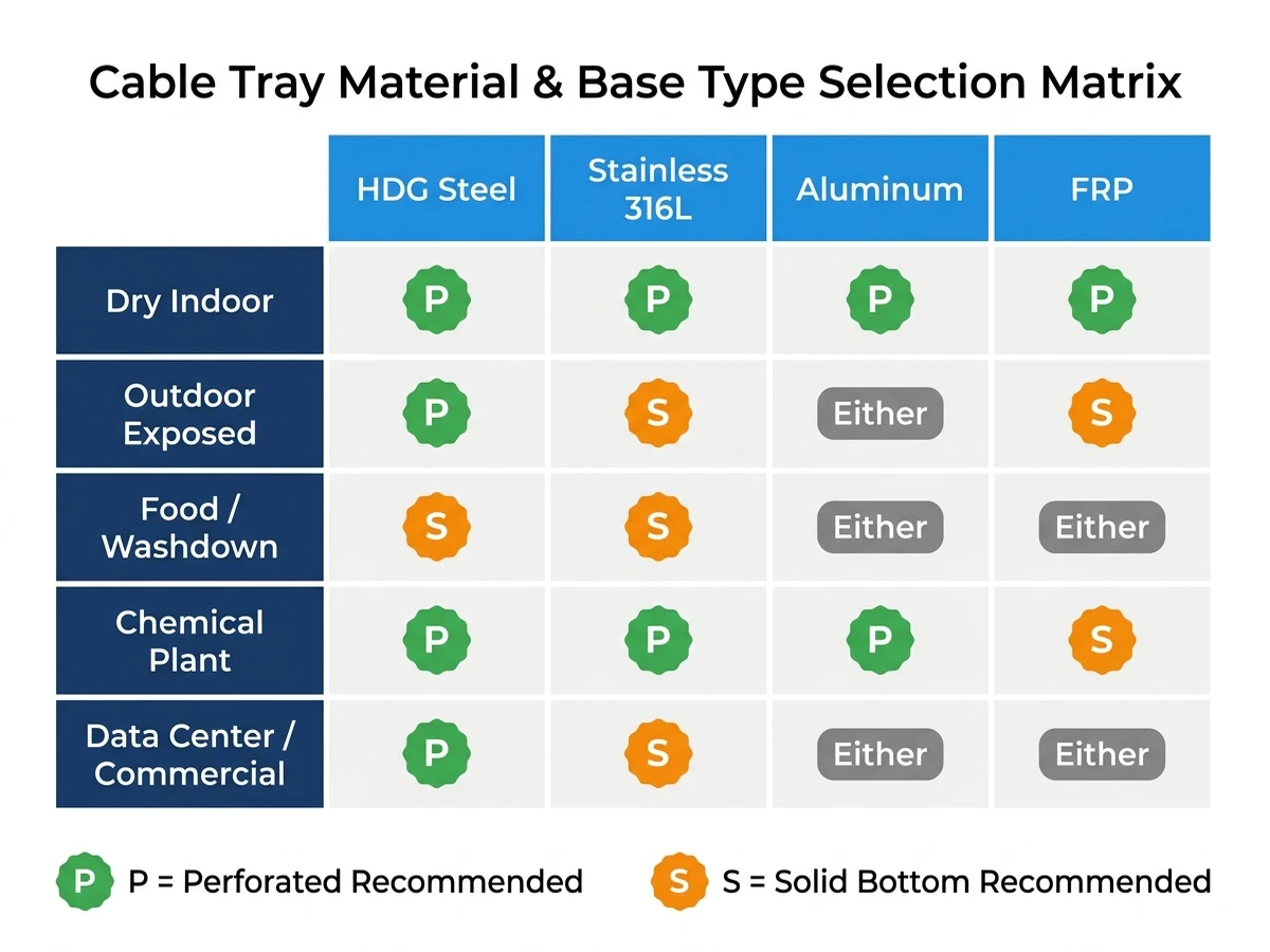
Map your environment first. A food processing facility with washdown zones needs solid bottom tray rated for appropriate IP enclosure, while a data center hot aisle with 8–12 kW/rack heat loads needs the 40–60% open area that perforated tray provides. In the Suzhou pharmaceutical project referenced earlier, both types were used on the same floor — solid in process areas with daily wash-down cycles, perforated in electrical rooms where ambient temperatures reached 38°C and ventilation was needed to keep cable surface temperatures within the 70°C limit for the installed PVC-insulated cables.
If your cables generate heat above 40°C ambient or carry currents requiring ampacity derating per IEC 60364-5-52, perforated tray is typically the right call. If your environment exposes cables to dripping liquids, falling debris, or corrosive particulates, solid bottom tray earns its place. When both conditions exist in the same run, transition fittings between tray types are standard practice — not a workaround.
For projects where cable tray size calculation is still in progress, locking in the tray type first simplifies the fill ratio and derating calculations that follow. The IEC 61537 load class framework — Class A through D — gives you a structured way to match cable fill weight to tray rating before procurement, which prevents the costly rework that comes from undersized trays discovered during installation.
Xinma’s engineering team works with contractors and specifiers on cable management system selection across industrial, commercial, and infrastructure projects. Whether you’re comparing material grades for a corrosive environment, sizing a solid bottom cable tray for a heavy power cable run, or working through a split-tray specification for a mixed-use facility, reach out with your project details — cable type, environment, span length, and load estimate — and we’ll point you toward the right configuration. You can also explore the full range of cable tray systems to see how perforated and solid options fit within a complete cable management design.
This page focuses on perforated tray selection. For adjacent topics, compare it with Perforated Cable Tray Systems, Perforated Cable Tray Guide, and Wire Mesh vs Perforated Cable Tray.
This article has been updated with explicit source and procurement checks so engineering, EPC, and purchasing teams can verify the recommendations instead of relying only on generic product descriptions. For project use, treat the table below as a starting evidence map and confirm the final requirements against local codes, consultant drawings, and supplier submittals.
| Reference or Xinma Resource | How Buyers Should Use It |
|---|---|
| IEC 61537 cable tray systems | Use this source to verify standards, product scope, installation assumptions, or supplier evidence before final specification. |
| NEMA VE 1 metal cable tray systems | Use this source to verify standards, product scope, installation assumptions, or supplier evidence before final specification. |
| NFPA 70 National Electrical Code | Use this source to verify standards, product scope, installation assumptions, or supplier evidence before final specification. |
| Xinma perforated cable tray systems | Use this source to verify standards, product scope, installation assumptions, or supplier evidence before final specification. |
| Xinma perforated cable tray guide | Use this source to verify standards, product scope, installation assumptions, or supplier evidence before final specification. |
| Xinma cable tray systems | Use this source to verify standards, product scope, installation assumptions, or supplier evidence before final specification. |
Perforated cable tray is generally the better choice when cables require ampacity derating management, ambient temperatures are elevated, or the installation is in a dry indoor environment like a data center or electrical room. The open base area — typically 30–50% — allows passive airflow that can reduce the derating factor from around 0.65 to 0.79 in high-density cable runs, which directly affects conductor sizing and material cost.
Solid bottom tray is well-suited for outdoor use, particularly where cables run beneath pipe racks, in areas with falling debris, or where direct solar shielding is needed. In high-irradiance climates, unshielded perforated trays have recorded tray floor temperatures up to 15°C above ambient, which can partially offset their ventilation advantage.
Solid bottom trays are typically limited to around 30% cable fill to maintain safe operating temperatures, while perforated trays can accommodate up to 40% fill under the same thermal constraints. Exceeding these thresholds in solid trays generally requires either conductor upsizing or increased mechanical ventilation in the cable routing space.
At the same material gauge and span, load ratings are broadly comparable — both types are classified from Class A (50 kg/m) through Class D (200 kg/m) under IEC 61537. Solid bottom trays are more often specified at heavier gauges because they tend to carry denser cable fills, which increases self-weight and shifts the load calculation toward the support structure.
Perforated trays allow visual cable inspection from below without disturbing existing cables, which can reduce inspection time considerably in dense installations. Solid bottom trays require working from above and moving cables aside, which increases labor time and the risk of incidental damage to adjacent cable jackets during routine checks.
In facilities with both high cable heat loads and exposure to dripping liquids — certain pharmaceutical or chemical processing areas — a split approach is common practice. Perforated tray handles the ventilation-critical runs, solid tray covers the wet or contaminated zones, and standard transition fittings connect the two sections without requiring custom fabrication.
Calculate the total cable fill weight per meter for your heaviest loaded run, then match that figure to the IEC 61537 load class — Class A at 50 kg/m, Class B at 75 kg/m, Class C at 100 kg/m, Class D at 200 kg/m. Confirm the selected tray’s rated span matches your actual support spacing, since load class ratings are span-dependent and a tray rated at Class C on 1.5 m spans may only achieve Class B at 1.8 m.
