Bus duct is an enclosed electrical power distribution system that carries current through copper or aluminum busbars inside a protective housing. In many projects, the same product family is also called busway or busbar trunking. The name changes by market and specification habit, but the practical question is the same: how should high-current power be routed safely, compactly, and inspectably through a building or industrial site?
Use this guide as a foundation before moving into detailed current rating, feeder/plug-in selection, installation checks, or supplier comparison. It explains the terms, the main components, where electrical bus duct fits, and what buyers should verify before issuing a purchase order.
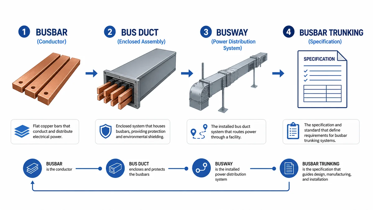
Bus duct, busway, and busbar trunking usually describe the enclosed power distribution system; busbar can refer only to the conductor.
What Is Bus Duct?
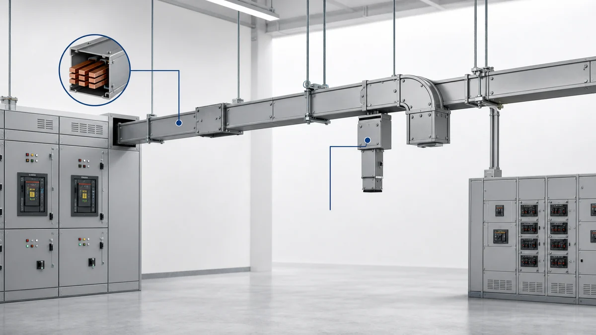
Bus duct, or electrical bus duct, is a prefabricated assembly that uses insulated busbars inside a metal enclosure to distribute power from one electrical point to another. A complete busway system normally includes straight sections, joints, elbows, flanges, end feed units, tap-off interfaces, hangers, covers, and accessories.
The simplest definition is this: bus duct is a routed power path built around enclosed busbars instead of many separate parallel power cables. It may connect transformer to switchgear, switchgear to a main distribution board, a riser to each floor, or a plug-in route to production equipment or data hall loads.
Bus duct is usually evaluated when a project needs high current, a compact route, repeatable section geometry, clear joint locations, or easier future load access. It is not automatically better than cable distribution. It becomes useful when the electrical rating, route density, tap-off plan, and installation access justify a complete busbar-based system.
In an anonymized Shanghai commercial riser coordination review in 2025, checking busway section IDs and joint access before procurement removed eight hidden joint locations from the draft route across an 18-floor riser. That type of review is a good example of how bus duct selection is both electrical and spatial.
Bus Duct, Busway, Busbar, and Busbar Trunking
The terms overlap, but they are not identical.
A busbar is the conductive bar itself, usually copper or aluminum. Busbars can be inside switchgear, panelboards, distribution boards, or an enclosed bus duct route. By itself, busbar does not necessarily mean the complete assembly.
Bus duct and busway normally refer to the enclosed system: conductors, insulation, enclosure, joints, fittings, supports, and access points. “Busway” is common in product catalogs and engineering discussions. “Bus duct” is still widely used by contractors, buyers, and site teams.
Busbar trunking system is common in IEC-style or international project documentation. When specifications refer to busbar trunking, engineers should confirm the exact product boundary: conductor material, enclosure, joint pack, tap-off units, end feed units, accessories, supports, testing evidence, and installation documents.
The naming issue matters because different documents may use different terms for the same scope. A consultant may write busbar trunking system, a supplier may quote busway, and an installer may ask about bus duct clearance. Before procurement, align the single-line diagram, route drawing, BOQ, and supplier quotation so everyone is pricing the same system.
How an Electrical Bus Duct System Works
An electrical bus duct system carries current through enclosed conductors. The current path usually starts at a transformer, generator connection, switchboard, or main distribution board, then passes through straight sections, joints, fittings, and sometimes tap-off units before reaching downstream panels or equipment.
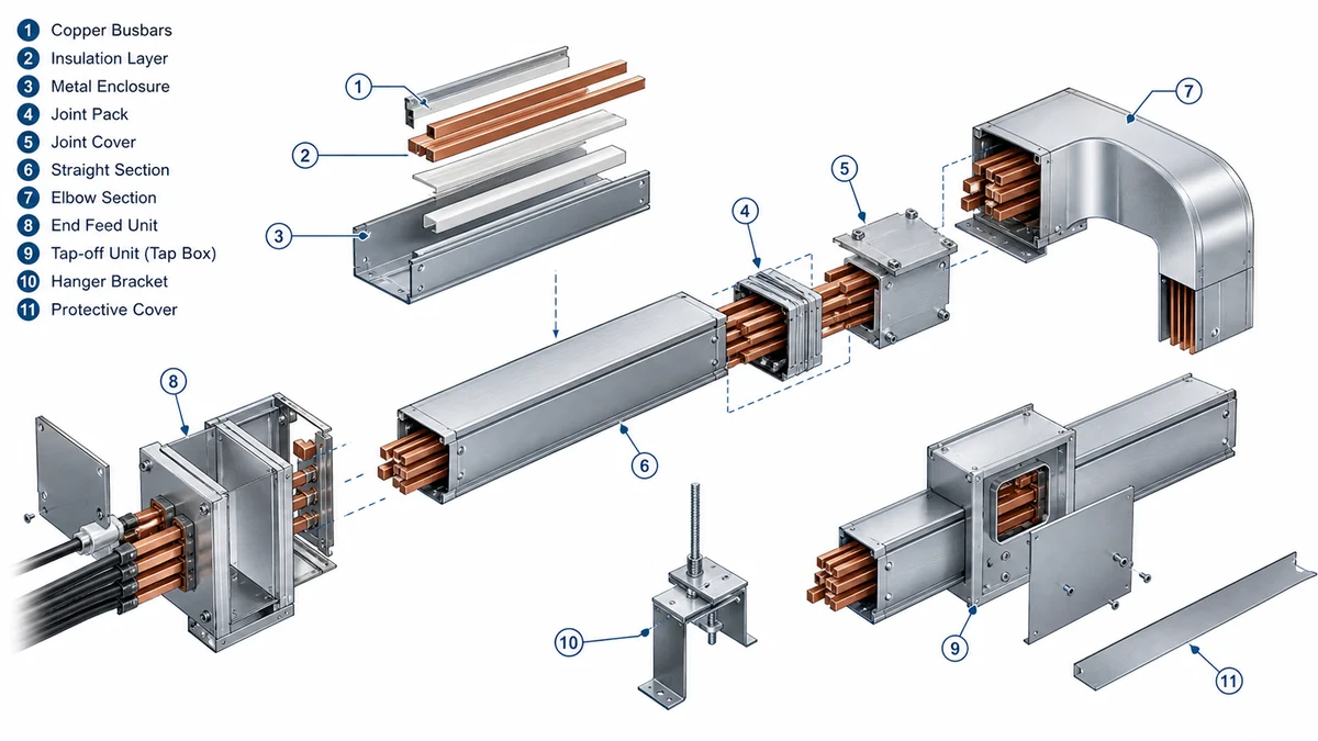
The main elements are straightforward:
Conductors: copper or aluminum busbars arranged by phase, neutral, and protective earth configuration.
Insulation: material and spacing that separate live conductors from each other and from the enclosure.
Enclosure: the housing that protects the conductors and helps define mechanical alignment, heat dissipation, and route geometry.
Joints: connection points between busway lengths. These need correct contact pressure, alignment, torque control, and inspection access.
Fittings: elbows, offsets, reducers, flanges, end feeds, and expansion sections that adapt the route to the building.
Tap-off units: connection boxes used when loads need to be fed along a plug-in busway route.
Supports: hangers, brackets, and structural fixings that keep the system aligned and accessible.
A bus duct system includes conductors, insulation, enclosure, joints, fittings, tap-off interfaces, and supports.
The joint is one of the most important installation interfaces. A busway route can be correctly rated on paper but hard to maintain if joint packs are hidden behind ceilings, walls, ducts, or other services. For this reason, route drawings should identify each joint, tap-off position, support point, cover access direction, and inspection clearance before release for manufacturing.
Feeder Busway and Plug-In Busway
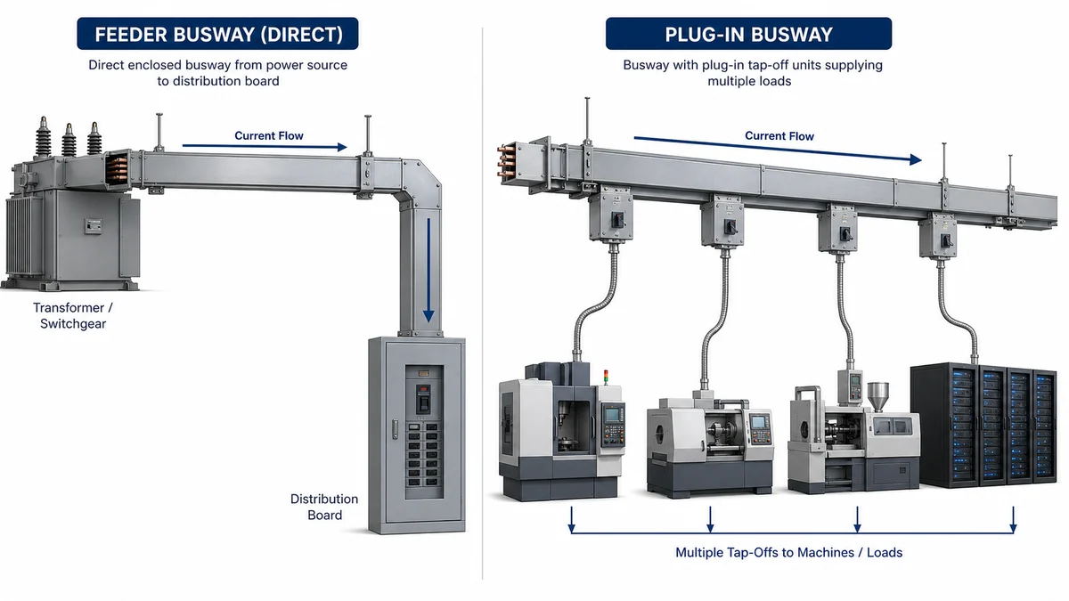
Most bus duct discussions lead to two common types: feeder busway and plug-in busway. A feeder route moves power point to point, such as transformer to switchgear or switchgear to a main distribution board. It normally has few or no intermediate tap-offs.
Plug-in busway is used where loads are distributed along the route. Tap-off units can feed production machines, commercial floors, rack rows, tenant areas, or modular load zones. The route needs more attention to tap-off spacing, operating access, protective device coordination, and future load changes.
For a more detailed decision path, use the dedicated guide to plug-in busway vs feeder busway. The short version is simple: choose feeder busway when the destination is fixed and high-current transfer is the main goal; choose plug-in busway when distributed load access is part of the design.
Feeder busway suits point-to-point distribution, while plug-in busway supports distributed tap-off loads along the route.
In an anonymized East China factory power-distribution review in 2024, the design team moved six tap-off locations before fabrication after checking machine access, crane coverage, and maintenance walkways against the busway route. The electrical rating did not change, but the route became easier to install and inspect.
Where Bus Duct Is Used
Bus duct is commonly evaluated in data centers, industrial plants, commercial buildings, high-rise risers, large mechanical rooms, manufacturing lines, and transit electrical rooms. It is attractive where large current must move through a compact route and where the project benefits from prefabricated sections, clear joint locations, and repeatable installation geometry.
It also has limits. Cable distribution remains practical for small loads, highly branched circuits, control wiring, instrumentation, mixed low-current services, or projects where individual cable changes are expected later. In those cases, a cable tray route with correctly selected cables may be more flexible and economical.
The decision should not be framed as busway always wins or cable always wins. Compare the load density, route length, available shaft or ceiling space, future changes, installation sequence, maintenance access, short-circuit duty, fire-stopping strategy, and site labor constraints. A dense riser or production route may favor bus duct. A widely branched plant corridor may still favor cable tray and cable.
How to Specify and Verify Bus Duct
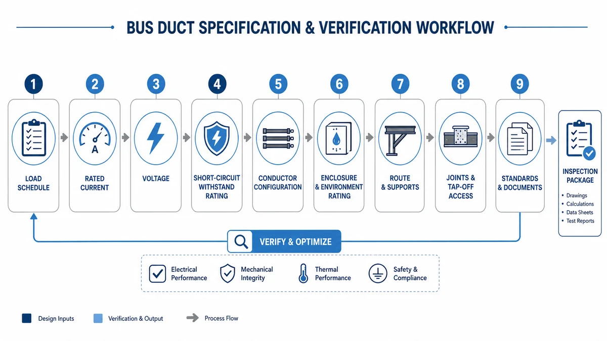
A bus duct specification should connect electrical duty with physical route and documentation. Start with the load schedule, system voltage, rated current, demand factor, future spare capacity, ambient temperature, conductor material, neutral/PE arrangement, and available fault level. Then check how the proposed busway product is verified for current rating, temperature rise, short-circuit withstand, enclosure protection, and installation method.
For rating selection, do not rely only on a catalog ampere number. Review ambient temperature assumptions, enclosure design, route orientation, harmonic profile if relevant, conductor material, and derating notes. The separate guide on busway current rating selection is useful when the load profile or future expansion plan is not simple.
International projects often reference IEC-style busbar trunking requirements. The applicable edition, scope, and test basis should be checked against the project specification and manufacturer documents; the official IEC 61439-6 busbar trunking systems publication page is the correct authority reference to start from. Do not treat a generic low-voltage assembly certificate as proof for every busway route.
Before order release, ask for route drawings, section breakdown, joint details, tap-off schedule, end feed interface, support plan, installation instructions, inspection points, packing list, and accessory list. If the supplier cannot map the BOM back to the route drawing, receiving inspection and site installation become harder.
Bus duct selection should connect load data, route geometry, ratings, standards evidence, documentation, and installation access.
Shanghai Xinma manufactures busway as part of a broader Xinma product ecosystem that also includes cable tray, fittings, accessories, and seismic bracing components. For project teams, the practical value is coordination: model codes, finishes, support geometry, tap-off and access interfaces, bill of materials consistency, and site inspection records can be reviewed together before delivery. This is specification and interface support, not a universal compatibility claim; final selection still depends on the project specification, route drawings, electrical study, and local approval requirements.
FAQ
Is bus duct the same as busway?
In many project documents, yes. Bus duct and busway usually refer to the same enclosed busbar-based power distribution system. Some specifications use busbar trunking system, especially in IEC-style documentation. Always confirm the full quoted scope, not only the name.
What is the difference between bus duct and busbar?
A busbar is the conductor. Bus duct is the assembled route that includes busbars, insulation, housing, joints, fittings, tap-off interfaces, supports, and connection units. In short, busbar is one component; bus duct is the complete distribution system.
Where is electrical bus duct commonly used?
It is commonly used in high-current routes for data centers, factories, commercial buildings, risers, utility rooms, production lines, and large electrical rooms. It fits best where compact routing, repeatable installation, and clear load access matter.
How do engineers choose the current rating of bus duct?
Engineers start from the load schedule, demand factor, future capacity, system voltage, ambient temperature, conductor material, installation orientation, and fault level. They should then compare these requirements with verified manufacturer data instead of selecting only by nominal ampere rating.
What documents should buyers verify before ordering busway?
Buyers should verify datasheets, route drawings, section list, conductor material, current rating, short-circuit withstand data, temperature-rise evidence, enclosure/IP details, tap-off schedule, jointing instructions, support details, packing list, and inspection requirements.
Kevin Zheng
Kevin Zheng is a manager linked to Shanghai Xinma Busway & Cable Tray Co., Ltd. He writes technical content on cable tray systems, installation practice, sizing logic, load classes, and related standards for industrial and infrastructure applications.