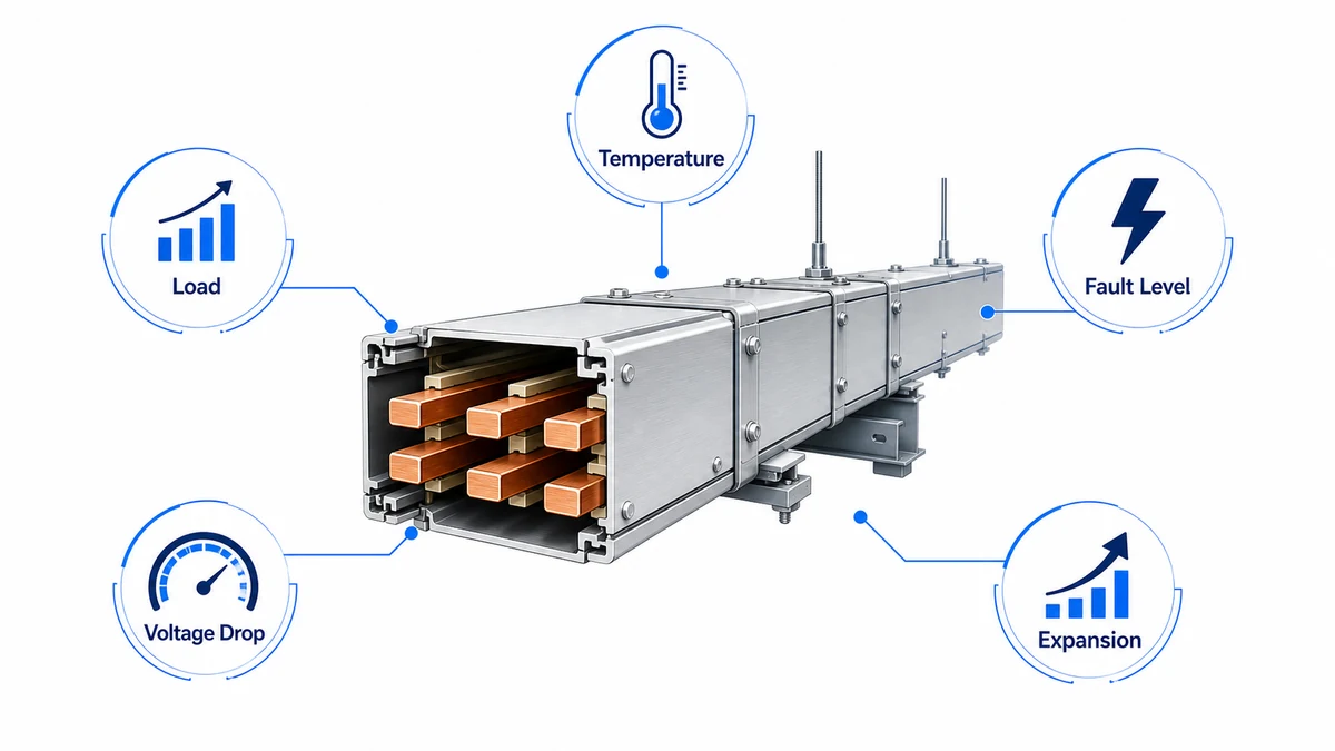
Selecting a busway current rating is not the same as choosing the next number above the load current. A busway route must carry the design load continuously, tolerate realistic ambient temperature, fit the short-circuit level, control voltage drop, allow future tap-offs, and match the installation environment. If one of those checks is skipped, the route may still look correct on the quotation sheet but run too hot, leave no expansion margin, or fail during technical submittal review.
For industrial plants and large commercial projects, busway systems are often used where a compact high-current backbone is cleaner than multiple parallel cable runs. The current rating should be selected from the project load schedule, but it must be verified against the manufacturer’s tested design, not calculated from conductor area alone.
The rating process starts by separating connected current, operating current, and selection current.
Start With the Load Schedule, Not the Catalogue
The first input is the real load schedule. For a three-phase route, engineers normally review connected load, demand factor, operating diversity, motor starting behavior, continuous load, spare capacity, and any future expansion plan. A 1600 A busway selected for a 1500 A calculated load may look acceptable at first glance, but it may be too tight if several large loads run continuously or if the client expects more tap-off points later.
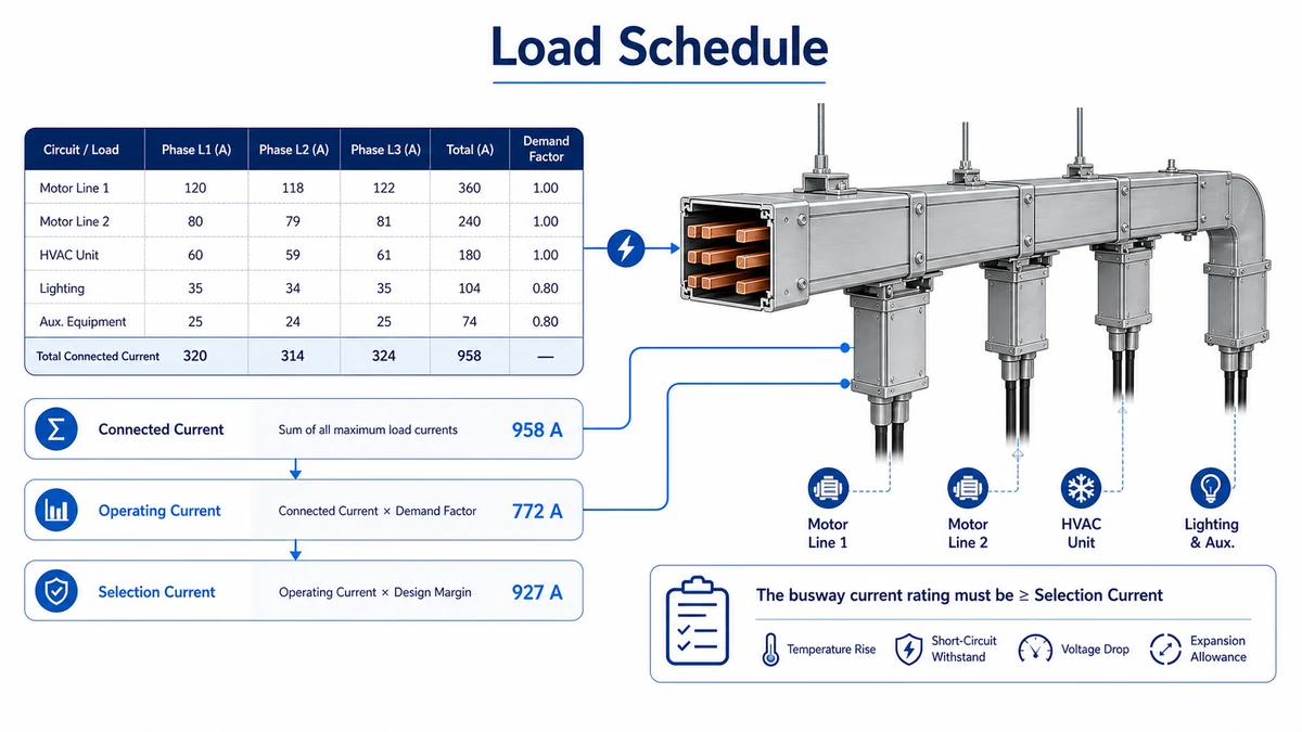
A practical starting rule is to separate three values:
Connected current: the sum of downstream equipment ratings.
Design operating current: the expected current after demand and diversity assumptions.
Selection current: the value used to choose the busway rating after margin, environment, and expansion checks.
The selection current should be documented. If the only note says “select 2000 A busway”, the supplier cannot see whether the rating came from a real calculation, a rule of thumb, or a copied drawing from another project.
Check Continuous Current and Future Margin
Industrial routes often change after commissioning. Production lines add machines, data rooms add racks, and commercial tenants request extra branch power. A busway rating with no spare capacity can become a bottleneck long before the mechanical route is worn out.
In an anonymized Shanghai electronics factory expansion in 2024, a 1250 A route was initially proposed for a production area with about 1040 A estimated operating current. After reviewing the client’s second-phase machine list, the project team moved to a 1600 A plug-in busway. The change kept roughly 25 percent usable planning headroom and avoided a later feeder replacement within the same ceiling corridor.
That does not mean every project needs a large oversize. Too much oversizing can increase cost, hanger load, space demand, and tap-off mismatch. The rating should follow the expansion plan: fixed plant with no spare bays can use tighter margins; production lines and tenant areas usually need more reserve.
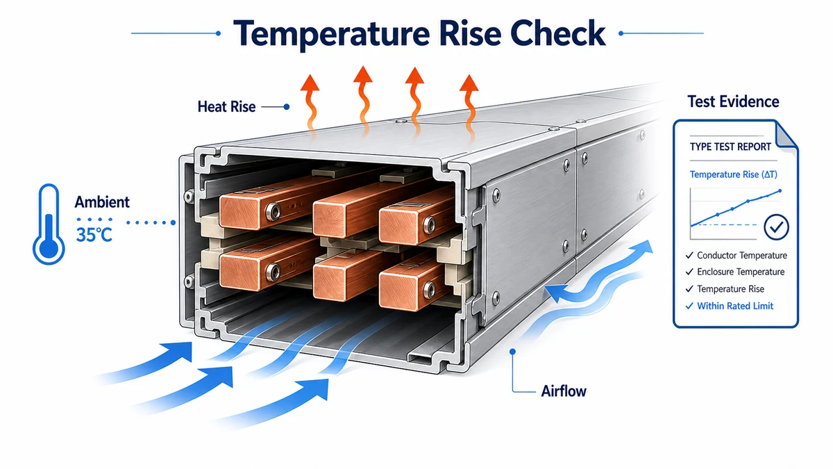
Match the Rating to Temperature Rise Evidence
Busway current rating depends on temperature rise, enclosure design, conductor material, joint structure, insulation system, ventilation condition, and installation orientation. Two busways with the same nominal ampere rating can behave differently if one uses different conductor geometry, enclosure size, joint design, or insulation class.
IEC 61439-6 covers busbar trunking systems and should be read together with the broader IEC 61439 assembly framework. The official IEC 61439-6 publication page identifies the standard as covering low-voltage busbar trunking systems, including construction and verification requirements.
For buyer-side review, ask for temperature-rise test evidence for the actual rating family. The supplier’s answer should connect the quoted busway rating to test reports, conductor material, neutral arrangement, enclosure protection, and installation method. If the quotation only lists “2000 A aluminum busway” without test context, the rating is not yet fully reviewable.
The selected rating must match tested temperature-rise evidence for the busway family.
Include Ambient Temperature and Installation Position
Ambient temperature is often underestimated. A factory roof space, transformer room, plant mezzanine, or poorly ventilated electrical shaft may operate hotter than the nominal design assumption. Higher ambient temperature reduces thermal margin, especially where the route is enclosed or near other heat-producing equipment.
Installation position also matters. Horizontal runs, vertical risers, edgewise conductor orientation, stacked routes, and restricted ventilation zones can affect heat dissipation. The manufacturer should confirm whether the quoted rating applies to the proposed installation position and enclosure protection level.
In an anonymized Suzhou industrial plant review in 2023, a 2000 A busway route passed the load-current check but failed the site coordination review because part of the run crossed a high-temperature process mezzanine. The final design kept the same nominal rating but changed the route zone and added stronger clearance rules, reducing expected thermal stress during summer operation.
This is the point where current rating becomes a site decision, not only an electrical number.
Verify Short-Circuit Withstand Before Freezing the Rating
Current rating tells you how much load the busway can carry continuously. Short-circuit withstand tells you whether the system can tolerate a fault until upstream protection clears it. Both are required.
A rating review should include rated operational voltage, rated current, short-time withstand current, peak withstand current, fault duration, upstream protection setting, and the location of the busway relative to transformers and switchboards. A route close to a transformer may face a higher prospective fault level than a downstream branch.
This check should happen before procurement. If the short-circuit level changes after the supplier has selected a busway family, the product line, joint design, or tap-off equipment may need to change. For high-current routes, the cost impact can be larger than the difference between two ampere ratings.
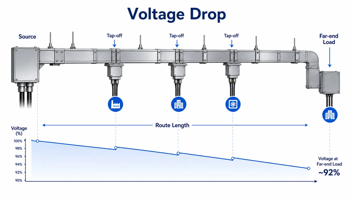
Do Not Ignore Voltage Drop and Route Length
Busway voltage drop is usually reviewed from manufacturer data. It depends on current, route length, conductor material, impedance, power factor, and layout. Long factory routes and data center corridors need this check because voltage drop can affect downstream equipment, even when current rating and thermal checks pass.
Voltage drop is especially relevant when the route includes many tap-offs along a long line. The far end may not see the same voltage condition as the first branch. Ask the supplier to provide voltage-drop data or a route-specific calculation when the run is long, heavily loaded, or feeding sensitive equipment.
This is also where cable tray systems enter the comparison. Cable routes and busway routes are not sized the same way, but both need a documented voltage and load path. If the project still uses power cables in some zones, the related cable tray size calculation workflow can help keep cable-support assumptions separate from busway current selection.
Long busway routes need voltage-drop review in addition to ampere rating checks.
Decide Between Plug-In and Feeder Busway
The current rating is tied to busway type. Plug-in busway is useful when loads need repeated tap-off points along a route. Feeder busway is usually used for point-to-point high-current distribution, such as transformer to switchboard, switchboard to riser, or switchboard to a major distribution zone.
Plug-in routes should be reviewed for tap-off spacing, tap-off box ratings, branch protection, access clearance, and future branch loading. Feeder routes should focus on current, voltage drop, short-circuit withstand, enclosure rating, joint count, and route geometry.
If a route needs frequent tap-offs, selecting only by the main busway ampere rating is incomplete. A 2000 A busway with poorly planned tap-off ratings can still fail the operational requirement. If a route has no branches, paying for plug-in flexibility may not add value.
Coordinate Supports, Seismic Requirements, and Access
Busway current rating affects physical size and weight. Larger ratings may require stronger hangers, shorter support intervals, different wall openings, or more careful vertical riser support. The support design should not be left until installation day.
For industrial or infrastructure projects in seismic zones, coordinate the current rating with seismic bracing requirements. Heavier busway sections and tap-off boxes can change restraint loads and bracket details. Even in non-seismic projects, routes near cranes, vibration sources, or heavy maintenance access zones need support review.
Where cable tray and busway share a corridor, the cable tray support logic is still useful as a reminder: supports near bends, risers, equipment interfaces, and loaded fittings often decide whether a route performs well in the field.
Buyer Checklist Before Approving the Rating
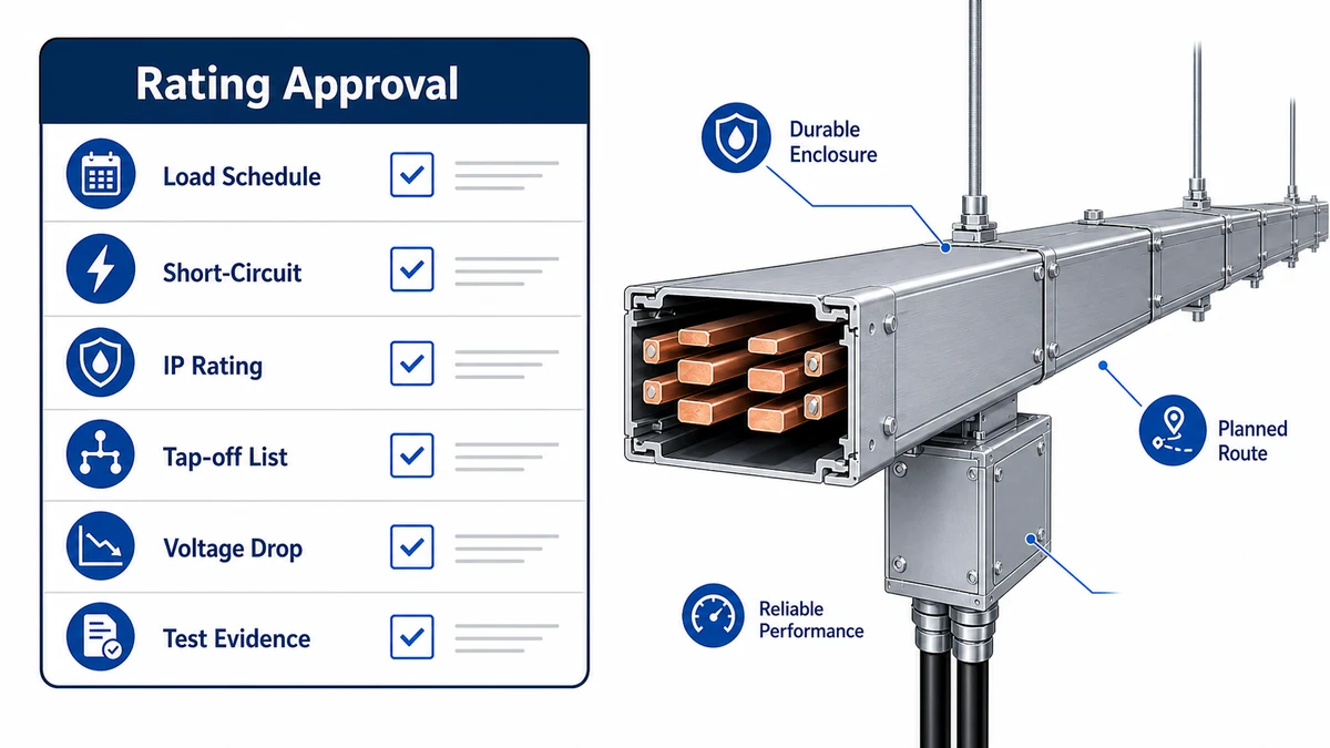
Before approving a busway rating, ask the supplier and electrical designer for a short, traceable selection file. It should include the load schedule, selected rating, conductor material, voltage, frequency, short-circuit withstand, IP rating, ambient condition, installation orientation, route length, tap-off list, voltage-drop basis, test evidence, and installation manual.
Procurement should approve a traceable rating file before ordering the busway system.
For mixed building systems, also check where busway ends and cable-management routes begin. Heavy cable support zones should not be confused with enclosed current-carrying busway.
Shanghai Xinma manufactures busway, cable tray, fittings, accessories, and seismic bracing components within the same product ecosystem. That matters when a selected busway rating changes section size, hanger load, tap-off clearance, or the support interface beside cable tray routes. The value is not a marketing ranking; it is the ability to keep model codes, finishes, support geometry, and inspection documents consistent from bill of materials to site inspection.
When specifying Xinma products, use the live busway product page as the primary landing page for rating and route review, and cross-check tray support compatibility against the relevant cable tray system and seismic bracing pages before finalizing the order.
A good selection process gives procurement something clear to compare. It also protects the project from a common mistake: buying a lower ampere rating because it meets a simplified load number, then discovering during submittal review that temperature, fault level, tap-off planning, or future expansion requires a different system.
Frequently Asked Questions
How do I choose a busway current rating?
Start with the load schedule, calculate the expected operating current, add a project-specific margin, then verify the selected rating against temperature rise, short-circuit withstand, voltage drop, ambient temperature, installation position, and future tap-off needs.
Is busway current rating the same as busbar size?
No. Busbar size affects current capacity, but the final busway rating also depends on enclosure design, insulation, joints, temperature-rise test evidence, ventilation, installation orientation, and short-circuit verification.
How much spare capacity should an industrial busway have?
There is no universal number. Fixed-load routes can use tighter margins, while production lines, tenant areas, and data halls usually need more reserve. The spare capacity should match the documented expansion plan, not a generic oversizing habit.
Does ambient temperature affect busway rating?
Yes. A hotter installation zone reduces thermal margin. Busway routes near roofs, process equipment, transformer rooms, or poorly ventilated shafts should be reviewed against the supplier’s temperature-rise evidence and rating conditions.
What documents should I request before approving a busway rating?
Request the load schedule, selected rating basis, conductor material, short-circuit withstand data, voltage-drop data, IP rating, route drawing, tap-off list, temperature-rise evidence, type-test information, and installation manual.
Kevin Zheng
Kevin Zheng is a manager linked to Shanghai Xinma Busway & Cable Tray Co., Ltd. He writes technical content on cable tray systems, installation practice, sizing logic, load classes, and related standards for industrial and infrastructure applications.