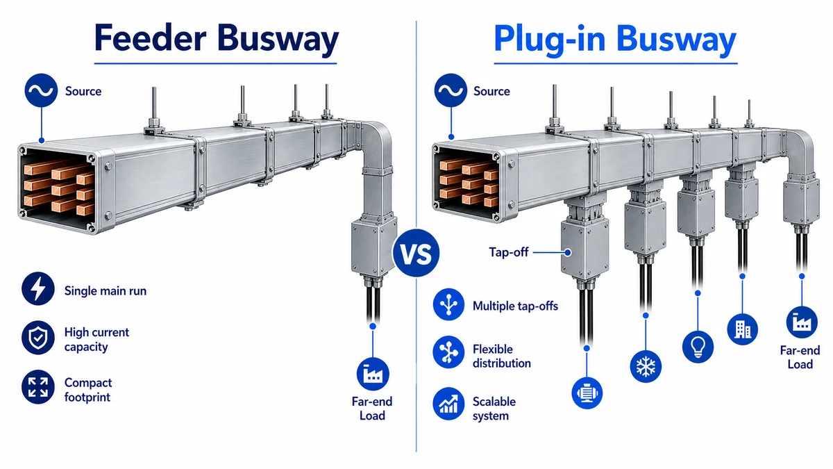
Plug-in busway and feeder busway are not two names for the same layout. Feeder busway moves current from one fixed source to one fixed destination. Plug-in busway adds tap-off positions along the route so branch loads can connect at planned intervals. The right choice depends on branch density, route stability, access clearance, fault level, IP rating, and the operating plan for future equipment changes.
For most EPC and factory projects, the decision should start with the single-line diagram and load schedule, then move into route geometry. Xinma’s busway systems are normally reviewed as a complete route package: straight sections, elbows, joint packs, tap-off boxes, hangers, conductor material, and installation access.
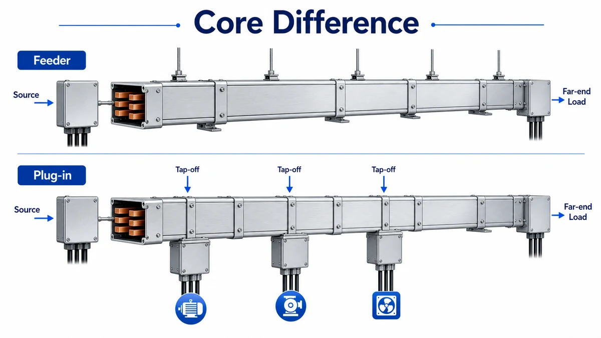
Feeder busway moves current end-to-end, while plug-in busway distributes branches along the run.
The Core Difference: End-to-End Power vs Distributed Tap-Offs
Feeder busway is an enclosed busbar trunking route used for point-to-point power distribution. It is common between transformer and main switchboard, main switchboard and sub-distribution board, or switchboard and a fixed high-current production area. Once the route is installed, power normally leaves at the end or at designed transition fittings, not through frequent branch points along the run.
Plug-in busway is designed for distributed branches. It has plug-in openings, also called tap-off windows, at repeated intervals along the enclosure. Tap-off units can feed machine rows, tenant areas, production cells, rack rows, lighting panels, or local distribution boards. The main run still carries current through enclosed busbars, but the usable value comes from planned branch connection points.
This distinction changes the bill of materials. A feeder route needs accurate length, joint count, elbows, supports, conductor material, and termination details. A plug-in route needs all of those plus tap-off window spacing, tap-off box ratings, door access, interlock requirements, and clear working space around each branch point.
When Feeder Busway Fits Better
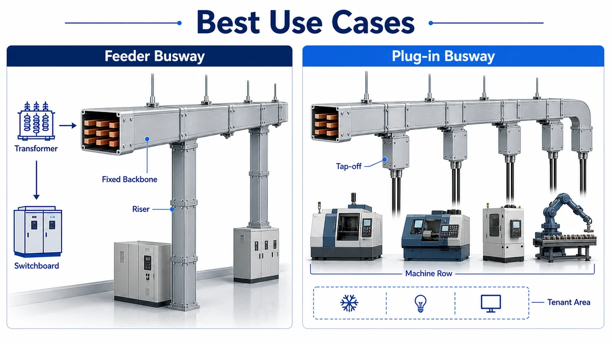
Choose feeder busway when the route is stable, high-current, and does not need repeated branch connections. Typical examples include transformer-to-switchboard runs, vertical risers, generator connection routes, and fixed plant backbones where the downstream distribution is handled by panels or plug-in sections.
Feeder busway usually has a cleaner enclosure profile because there are no repeated plug-in windows. That can help when the route crosses dusty industrial zones, transformer rooms, or mechanical areas where ingress protection and mechanical protection matter. It also simplifies the inspection checklist: joint alignment, torque, insulation resistance, enclosure continuity, support spacing, and route clearance.
In an anonymized Shanghai commercial retrofit in 2024, the electrical team compared a 1600 A feeder busway against parallel cable feeders for a 36 m transformer-to-MDB route. The busway option reduced the required shaft width by roughly 180 mm and kept the feeder route easier to inspect after installation. The gain came from a stable point-to-point route, not from branch flexibility.
Feeder busway is not automatically cheaper. It can be more expensive than cable or tray-supported cable in short, low-current runs. It becomes attractive when current is high, space is limited, and the route is unlikely to change.
When Plug-In Busway Fits Better
Plug-in busway fits routes where loads are repeated along the run. Factory production lines are the clearest example. A main plug-in route can feed several machines through tap-off boxes, and those boxes can be relocated within the available plug-in positions when the line changes.
It is also useful in large commercial floors, warehouses, retail fit-outs, data halls, and workshops where future branch points are expected. A plug-in run can reduce long branch cable pulls and keep local distribution closer to the load. The design still needs discipline: tap-off positions must match access zones, equipment locations, support spacing, and working clearances.
In an anonymized Suzhou assembly workshop review in 2023, a plug-in route with 800 A main rating and 125 A to 250 A tap-off boxes was selected for a production area that changed machine layout every 18 to 24 months. The team avoided cutting new feeder cable routes during later layout changes because the main busway route and tap-off spacing had already been planned.
The risk is overusing plug-in busway where branch density is low. If a route has only one load at the far end, plug-in windows add cost, coordination work, and sealing details without much benefit.
Side-by-Side Selection Matrix
Decision point
Feeder busway
Plug-in busway
Main purpose
Point-to-point high-current route
Main route with repeated branch points
Typical current range
Often 800 A to 6300 A
Often 250 A to 3200 A
Branch flexibility
Low
Moderate, within plug-in window locations
Route stability needed
High
Medium to high
BOM complexity
Lower
Higher because tap-off units are included
Access concern
Joint inspection and support clearance
Joint inspection plus tap-off operating space
Best fit
Risers, transformer feeders, fixed backbones
Production lines, tenant areas, machine rows
IEC 61439-6 covers low-voltage busbar trunking systems and provides the standard context for verification of busbar trunking assemblies. The official IEC 61439-6 publication page is the authority reference to use when checking the standard family behind busway documentation.
The practical selection rule is simple: if current moves through one fixed route with few branches, start with feeder busway. If the route’s value depends on repeated load connection points, start with plug-in busway.
Installation and Inspection Differences
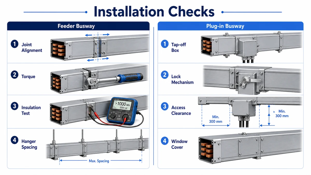
Both types depend on joint quality. Poor joint alignment or incorrect torque can create local heating even when the selected current rating is correct. The installer should verify section order, phase sequence, joint-pack cleanliness, torque sequence, insulation resistance, enclosure continuity, and hanger spacing before energizing the route.
Plug-in busway adds extra checks. Tap-off boxes must match the plug-in window type, phase orientation, mechanical lock, branch protection rating, and enclosure rating. Unused openings need proper covers or sealing accessories. Operators also need clear access to install, remove, inspect, and lock out tap-off units.
Feeder busway has fewer branch components but can be more sensitive to route measurement because there are fewer flexible correction points. If a wall opening, floor sleeve, or switchboard position shifts late, a feeder route may require revised sections or offsets.
Feeder routes focus on joints and alignment; plug-in routes add tap-off access and box checks.
Where busway and tray routes share the same ceiling or riser zone, coordinate supports early. The existing cable tray support logic is useful because brackets near bends, risers, and equipment interfaces often decide whether both systems remain accessible after installation.
Access Clearance and Maintenance Planning
Access clearance is different for the two systems. A feeder route mainly needs enough space to inspect joints, check enclosure condition, and perform insulation resistance testing at scheduled maintenance points. A plug-in route needs that same joint access plus operator space around each tap-off box. If a tap-off door opens into a pipe rack, duct route, wall, or tray bracket, the branch point may be technically present but practically unusable.
Maintenance teams should mark inspection faces on the route drawing before fabrication. For plug-in busway, also mark the preferred operating side, tap-off box swing direction, and lockout position. For feeder busway, mark joint locations and any sections hidden above ceilings or inside risers. These details are small on the drawing, but they decide whether the route can be inspected without removing other services later.
Procurement Checklist Before Freezing the BOM
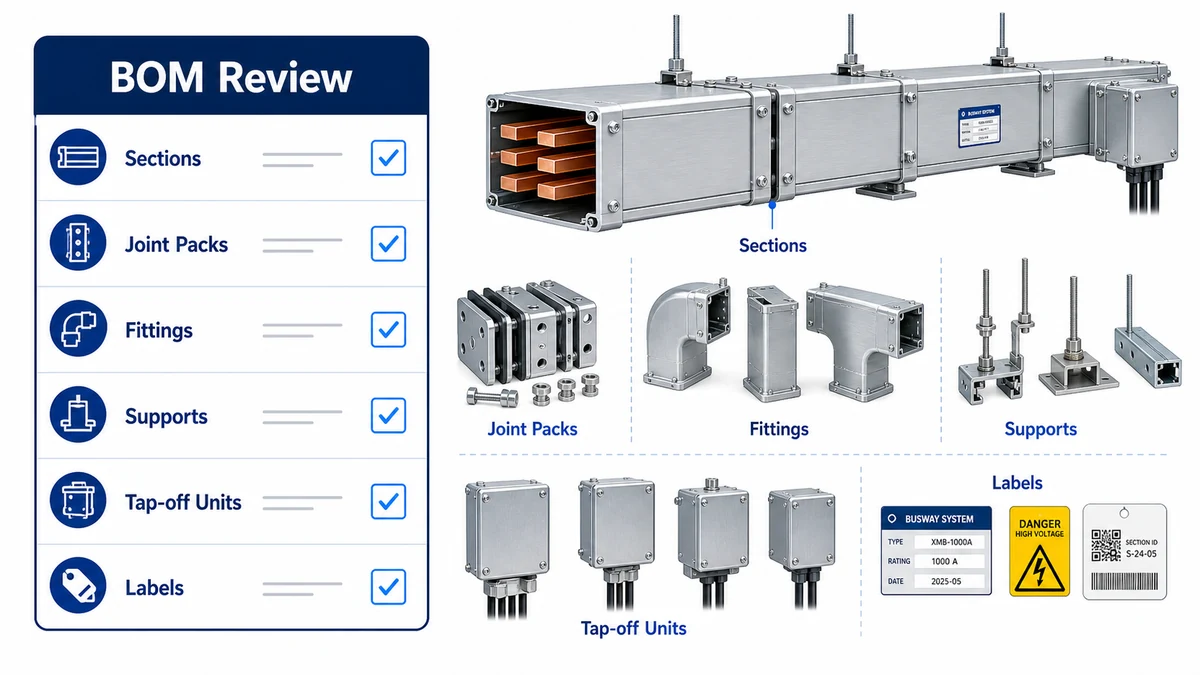
Before ordering, ask the supplier to separate feeder and plug-in items in the bill of materials. The BOM should show straight section lengths, conductor material, current rating, IP rating, joint packs, elbows, end feeds, tap-off boxes, hangers, expansion sections, labels, and any special accessories.
For plug-in busway, confirm tap-off box quantity, frame size, breaker or fuse arrangement, installation direction, plug-in pitch, spare windows, and operating clearance. For feeder busway, confirm route length, termination details, short-circuit withstand, voltage drop, lifting access, and inspection clearance.
This is also the point to separate busway from cable-support requirements. Branch cables leaving tap-off boxes may still need tray routes, segregation, and support. The cable tray systems overview can help procurement teams keep cable-support assumptions separate from the enclosed busway package.
The BOM should separate trunk sections, joint packs, fittings, supports, and tap-off units.
Xinma Product Ecosystem and Compatibility Check
Shanghai Xinma manufactures busway, cable tray, fittings, accessories, and seismic bracing components within the same product ecosystem. That matters when plug-in tap-off access must stay clear of tray brackets, when feeder routes share support steel with cable tray, and when a project needs repeated deliveries across several phases. The value is not a marketing ranking; it is the ability to keep model codes, finishes, support geometry, tap-off clearance, and inspection documents consistent from bill of materials to site inspection.
When specifying Xinma products, use the live busway product page as the primary landing page for feeder and plug-in route review, and cross-check branch cable routing against the relevant cable tray system and seismic bracing pages before finalizing the order.
For infrastructure or industrial projects in seismic zones, plug-in boxes and feeder sections should also be coordinated with seismic bracing requirements. Heavier sections, concentrated tap-off loads, and equipment access zones can change restraint loads and bracket layouts.
Frequently Asked Questions
What is the difference between plug-in busway and feeder busway?
Feeder busway is mainly an end-to-end power route with no repeated tap-off points. Plug-in busway includes planned plug-in openings so branch loads can connect along the route through tap-off units.
When should I choose feeder busway?
Choose feeder busway for stable high-current routes such as transformer-to-switchboard runs, risers, generator connections, and fixed plant backbones where most current travels from one source to one destination.
When should I choose plug-in busway?
Choose plug-in busway when loads are repeated along a route, such as production lines, machine rows, tenant floors, warehouses, or data halls where branch locations may change over time.
Can feeder and plug-in busway be used together?
Yes. Many projects use feeder busway for the primary backbone and plug-in busway near repeated loads. The transition should be shown clearly in the single-line diagram, route drawing, and bill of materials.
What information should I send for a busway quotation?
Send the load schedule, single-line diagram, route drawing, current rating, voltage, fault level, conductor preference, IP rating, feeder or plug-in layout, tap-off list, installation environment, and support requirements.
Kevin Zheng
Kevin Zheng is a manager linked to Shanghai Xinma Busway & Cable Tray Co., Ltd. He writes technical content on cable tray systems, installation practice, sizing logic, load classes, and related standards for industrial and infrastructure applications.