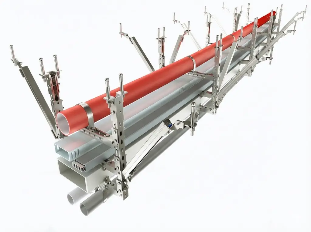
Seismic bracing for MEP systems is the restraint package that limits unwanted movement of pipes, HVAC ducts, cable trays, and related suspended services during seismic motion. A normal hanger supports vertical weight. A seismic brace controls lateral sway, longitudinal movement, uplift, and connection failure by creating a clear load path from the MEP element back to the building structure.
For EPC teams and MEP contractors, the practical question is not simply “which brace should we buy?” The better question is: which restrained element, load direction, structural landing point, clamp interface, anchor type, and inspection record are required for this route? XMQJ’s seismic bracing product range is designed around that system-level workflow.
Seismic bracing creates a load path from MEP services to the building structure.
1. What Seismic Bracing Does in an MEP System
MEP services often run above ceilings, inside plant rooms, along industrial corridors, and through data center utility zones. During seismic movement, these suspended systems can swing, twist, or shift along the route. The risk is not limited to the brace member itself. Uncontrolled movement can damage pipe joints, duct seams, cable tray fittings, equipment connections, and nearby services.
A complete restraint system normally includes:
Strut channel or rigid brace members
Pipe clamps, duct brackets, or tray clamps
Connector plates and angle fittings
Beam clamps, concrete anchors, or insert plates
Fasteners, washers, and finish-compatible hardware
Every part must match the same load path. A strong strut with an undersized anchor is not a reliable brace. A correctly anchored assembly with a clamp that does not fit the tray rail or pipe outside diameter is also not reliable. The restraint must be checked as an assembly.
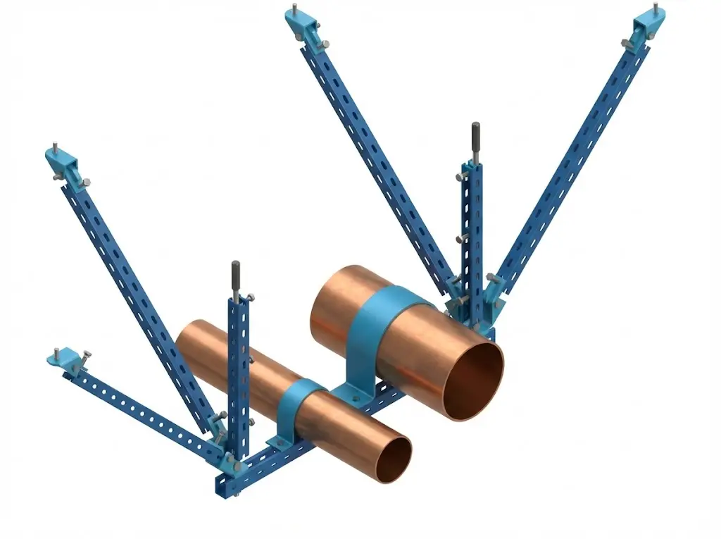
2. Pipe, Duct, and Cable Tray Restraint Are Not the Same
Pipes, ducts, and cable trays need different clamp interfaces and restraint details.
Pipe restraint usually focuses on round geometry, pipe outside diameter, insulation clearance, support elevation, and whether the service is water, fire protection, process fluid, or compressed air. Fire protection systems may have more specific project and authority requirements than general utility piping, so the approved design documents and authority having jurisdiction should be checked before procurement.
Duct restraint has a different problem: rectangular ductwork can be wide and flexible. The brace connection must avoid damaging the duct wall, flange, or seal. A heavy rectangular duct can need both lateral and longitudinal restraint, but the attachment detail must preserve the duct pressure and leakage requirements.
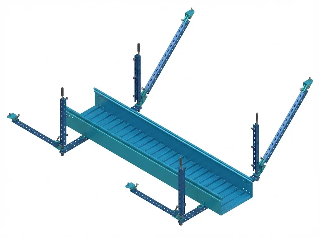
Cable tray restraint is closer to a distributed-load problem. The tray carries cable weight across spans, turns, risers, and fittings. A fully loaded tray can move sideways or along the run if only vertical hangers are installed. Tray clamps must fit the rail or flange profile. A clamp that works on a ladder tray may not fit a solid-bottom or perforated tray without a different jaw geometry. For tray profile and support context, see XMQJ’s cable tray systems overview.
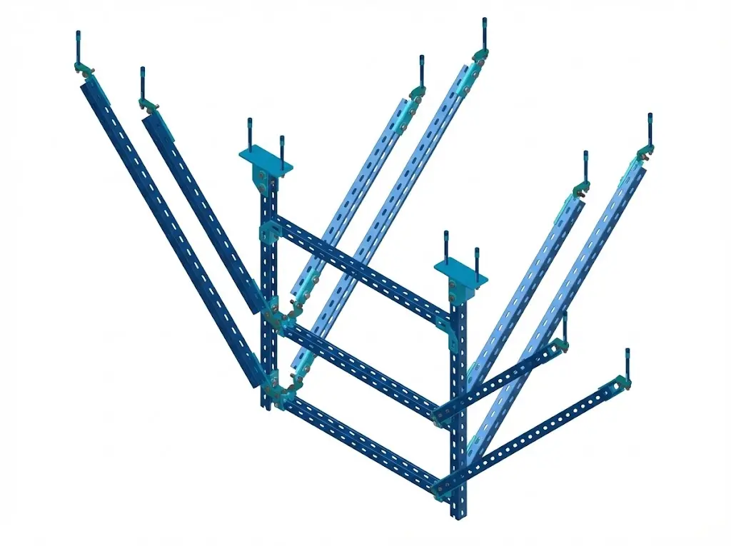
3. How Engineers Define the Brace Layout
The layout process starts with the restrained object and the structure, not the catalog page. The engineer or coordinator should confirm:
MEP element type: pipe, duct, cable tray, busway, or mixed route
Loaded weight and service importance
Lateral and longitudinal restraint requirements
Structural landing point: slab, beam, wall, or secondary steel
Anchor type and edge distance
Brace angle and clearance around other services
Corrosion environment and finish requirement
Brace locations should be coordinated with structure, fittings, and access zones.
Brace locations should be coordinated with pipe supports, duct hangers, cable tray fittings, access panels, and equipment maintenance zones. Field teams should not move a brace location only because it conflicts with another trade. A moved brace changes the load path and may require review by the engineer of record.
Where cable tray is involved, fittings and transitions need special attention. Elbows, tees, reducers, and vertical drops interrupt a straight run and can concentrate movement at splice points. Before finalizing the brace bill of materials, check the tray route against the cable tray fittings schedule and the cable tray installation guide.
4. Component Selection Checklist
A matched bracing package includes strut, clamps, connectors, anchors, and fasteners.
A reliable MEP bracing package should be specified as a matched set. The following checks reduce substitution risk:
Strut channel size matches the calculated brace force and brace length.
Connector plates and angle fittings are rated for the actual load direction.
Pipe clamps match pipe outside diameter, insulation clearance, and service type.
Duct brackets do not compromise duct seal or pressure class.
Tray clamps match rail height, flange width, and tray material.
Anchors are suitable for the substrate and installation condition.
Finish is consistent across strut, clamps, anchors, and fasteners.
Do not mix finish grades casually. For example, combining hot-dip galvanized strut with zinc-plated fasteners in a wet or outdoor area can create a weak point in the assembly. Outdoor, tunnel, coastal, and chemical environments may require hot-dip galvanizing, stainless steel, or a project-specific coating system.
XMQJ’s factory-side value is not a unverifiable ranking claim. It is the ability to coordinate cable tray, fittings, accessories, and bracing hardware so that clamp geometry, finish, packing lists, and model codes can be checked together before shipment.
For a mixed MEP package, that traceability is practical. A pipe clamp, tray clamp, and duct bracket may look similar in a packing zone, but each one has a different interface and inspection requirement. Route-based packing and model-code labels help the site team match the correct component to the approved drawing instead of relying on visual selection during installation.
5. Installation QA and Incoming Inspection
Installation QA should be visible and recordable. A completed brace should not rely on verbal confirmation. The site team should be able to show the drawing location, installed component model, anchor detail, torque record, and any approved field change.
QA records should verify brace angle, anchor torque, clamp seating, finish, and BOM traceability.
Use these hold points before ceiling closure or handover:
Confirm brace location against the approved drawing.
Check brace angle and clearances.
Verify anchor type, embedment, and torque.
Confirm clamp seating on pipe, duct, or tray.
Check finish continuity, especially at field-cut strut ends.
Photograph critical routes before they are concealed.
Record substitutions and obtain engineering approval before acceptance.
Incoming inspection should be equally strict. Strut channel should be checked for section size and coating. Clamps should be checked against pipe OD, duct detail, or tray rail profile. Anchor packages should show batch or product identification. Packing lists should separate components by route or installation zone so site crews do not mix similar-looking hardware.
For cable tray projects, IEC 61537 is a useful external reference for cable tray and cable ladder performance classification. It does not replace local seismic design requirements, but it helps procurement teams understand tray load and support terminology when reviewing bracing interfaces.
Frequently Asked Questions
What is seismic bracing for MEP systems?
Seismic bracing for MEP systems is a restraint assembly that limits lateral and longitudinal movement of pipes, ducts, cable trays, and related services during seismic motion. It transfers movement forces from the MEP element to the building structure through clamps, strut, connectors, and anchors.
Is a normal hanger enough for seismic restraint?
No. A normal hanger carries vertical gravity load. Seismic restraint needs diagonal or rigid bracing that can resist horizontal movement. A hanger may be part of the support system, but it should not be treated as the seismic brace unless the project design explicitly proves it.
Do pipes, ducts, and cable trays use the same brace hardware?
They can share some parts, such as strut channel and connectors, but the interface clamp is different. Pipe clamps, duct brackets, and cable tray clamps must match the shape, load, and installation detail of the restrained element.
How should brace spacing be decided?
Brace spacing should come from the project design, applicable code requirements, loaded weight, service importance, brace direction, and component capacity. Do not use a universal distance without checking the design basis and authority requirements.
What should be checked before ordering seismic bracing?
Confirm the MEP element type, route layout, loaded weight, substrate, anchor type, finish, clamp interface, and documentation requirements. The purchase order should include model codes, finish requirements, data sheets, and route-specific packing information.
How does cable tray type affect bracing?
Cable tray type affects clamp selection. Ladder tray, perforated tray, and solid-bottom tray have different rail and flange profiles. The tray clamp should be matched to the profile dimensions instead of selected only by tray width.
What documentation supports E-E-A-T and inspection quality?
Useful documentation includes component data sheets, material and finish records, anchor information, packing lists, installation photos, torque records, and approved field-change notes. These records show that the installed restraint system matches the design intent.
Kevin Zheng
Kevin Zheng is a manager linked to Shanghai Xinma Busway & Cable Tray Co., Ltd. He writes technical content on cable tray systems, installation practice, sizing logic, load classes, and related standards for industrial and infrastructure applications.