A network and data cable tray system is a rigid, open cable management structure designed to support, route, and protect low-voltage communication cables — including Cat6A, fiber optic, and coaxial runs — across buildings, data centers, and industrial facilities. Unlike enclosed conduit, cable trays allow unrestricted airflow around cables, simplifying heat dissipation and enabling fast adds, moves, and changes without pulling new conduit.
Cable tray is the default choice for high-density structured cabling precisely because of this open architecture. Fill ratio management, load classification, and material selection are the three decisions that determine whether a system performs reliably over its service life — or becomes a maintenance problem within a few years.
What Cable Tray Systems Are and How They Work
A cable tray system consists of two longitudinal side rails connected by rungs, a solid bottom panel, or a mesh grid, depending on the tray type. The assembly is suspended from structural ceilings or mounted to walls and equipment racks using hangers, brackets, and splice plates. Cables rest in the open tray rather than being threaded through enclosed conduit, which is what makes inspection, rerouting, and capacity additions so much faster.
In a 2023 hyperscale data center fit-out in Shenzhen (approximately 8,000 m² of raised-floor space), ladder-style cable trays at 600 mm width reduced structured cabling installation time by 28% compared to the previous conduit-based design. Technicians could lay and reroute cables without threading — a practical difference that compounds across thousands of cable runs.
What These Systems Carry
In structured cabling environments, trays typically support:
Horizontal copper runs (Cat6A, Cat8) with individual cable diameters of 6–8 mm
Multimode and single-mode fiber optic bundles requiring bend radius protection of at least 25 mm
Coaxial and AV signal cables in mixed-use commercial installations
IEC 61537, published by the International Electrotechnical Commission, governs cable tray and cable ladder systems. It defines load classes from 50 kg/m (Class A) up to 200 kg/m (Class D) and sets maximum allowable midspan deflection at L/200 under proof load — where L is the span between supports, typically 1.5 m to 3 m in network installations.
How Cable Trays Differ from Conduit
Conduit encloses cables in a sealed pathway, offering mechanical protection but limiting access and airflow. Cable trays are open or semi-open, which shifts the design challenge from routing to fill ratio management. IEC 61537 recommends cable fill not exceed 50% of the tray’s cross-sectional area to maintain cable accessibility and prevent excessive weight loading. Exceed that threshold and you’re not just risking a failed inspection — you’re creating thermal buildup and making future cable additions unnecessarily difficult.
The Three Primary Tray Forms
Three structural types appear in most structured cabling installations:
Ladder tray: two longitudinal rails connected by rungs spaced 150–300 mm apart, suited for heavy cable bundles over long spans with maximum airflow
Solid-bottom tray: continuous base with side rails, used where cables need physical protection from debris or where EMI shielding from below is a concern
Wire mesh tray (cable basket): welded wire grid, typically 1.2–2.5 kg/m, preferred in data centers and server rooms for its light weight and flexibility around obstructions
Each type serves a distinct routing scenario. Selection depends on span length, cable weight, environmental exposure, and applicable local fire-rated cable management requirements.
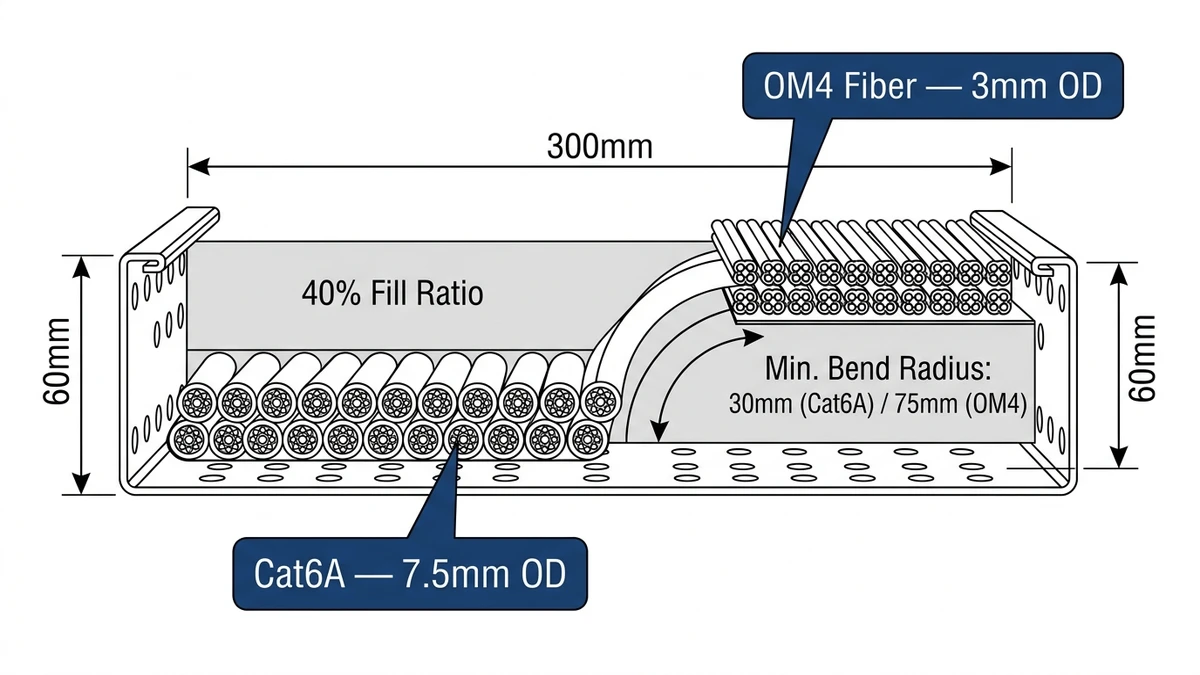
Figure 1. Cable tray cross-section showing Cat6A copper and OM4 fiber cable population at 40% fill ratio, with minimum bend radius arc (30mm for Cat6A, 75mm for OM4 fiber) and tray dimensional callouts for width and depth.
[Expert Insight]
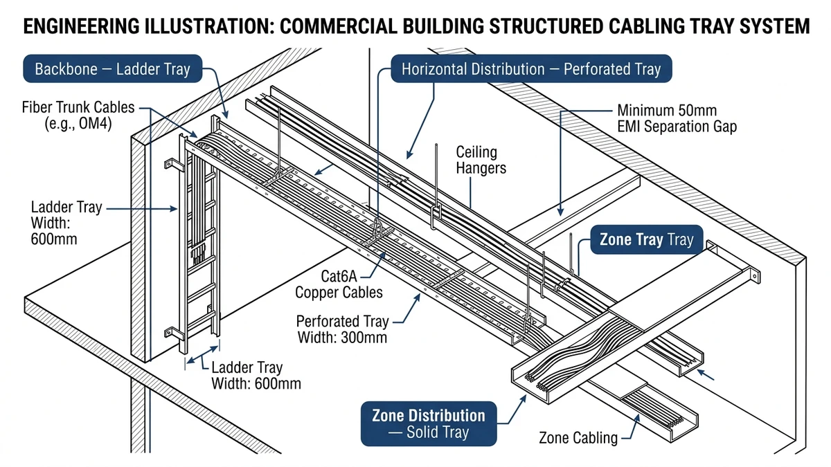
– In dense horizontal distribution zones, ladder trays at 600 mm width with 40% fill leave enough headroom to absorb a mid-project scope change without replacing tray sections — a common occurrence in phased data center buildouts.
– Fiber optic bundles are the most sensitive to fill ratio violations; even moderate overcrowding can introduce micro-bend losses that don’t show up until post-installation testing.
– Wire mesh trays are faster to install than ladder trays in above-ceiling runs, but their lower moment of inertia means support spacing typically needs to drop from 3 m to 1.5 m to stay within IEC 61537 deflection limits.
– Always verify that tray material is galvanically compatible with cable hardware — aluminum trays in contact with copper fittings in humid environments can accelerate corrosion at contact points.
How Cable Trays Are Classified and Constructed
Cable tray classification defines the mechanical load a system can safely carry across a given span without exceeding allowable deflection. Understanding these ratings is essential before specifying any cable management system for structured cabling — the wrong load class leads to sagging trays, cable damage, and failed inspections.
Load Classes Under IEC 61537
IEC 61537 (Cable management — cable tray systems and cable ladder systems) defines four load classes based on uniformly distributed load capacity, all tested at a reference span of 3 m:
Class A: 50 kg/m — light-duty, typically horizontal runs in office environments
Class B: 100 kg/m — medium-duty, common in commercial data rooms
Class C: 150 kg/m — heavy-duty, suited for dense structured cabling in enterprise or industrial settings
Class D: 200 kg/m — extra heavy-duty, used in high-density data centers or cable riser shafts
Maximum allowable midspan deflection is L/200 across all classes — meaning a 3 m span must not deflect more than 15 mm under proof load. A 2.5 m span permits no more than 12.5 mm. These are hard limits, not guidelines.
Span and Deflection in Practice
In a 2023 enterprise campus project in Guangzhou covering approximately 12,000 m² of structured cabling infrastructure, ladder cable trays rated Class C at 600 mm width were installed on 2.5 m support intervals. Under full cable fill — roughly 85 kg/m of Cat6A and fiber — measured midspan deflection averaged 9 mm, comfortably within the IEC 61537 Class C limit. Reducing support spacing from 3 m to 2.5 m was the key adjustment that kept deflection within spec without upgrading to a heavier tray profile.
For a deeper look at how support spacing interacts with tray performance, the cable tray support spacing guide covers span calculations and hanger configurations in detail.
Material and Finish Options
Cable trays are manufactured in steel (hot-dip galvanized or pre-galvanized), stainless steel, aluminum, and fiberglass-reinforced plastic (FRP). Hot-dip galvanized steel, with a zinc coating thickness of at least 45 μm per ISO 1461, is the most common choice for general structured cabling environments due to its corrosion resistance and cost efficiency. Aluminum trays are preferred where weight is a constraint — typically 60% lighter than equivalent steel trays — and in environments where galvanic compatibility with copper cabling hardware is a concern.
Stainless steel (Grade 304 or 316) is required in food processing, coastal, or chemical plant installations where chloride exposure is continuous. FRP trays handle aggressive chemical environments where metallic trays would corrode within months, with operating ranges typically spanning -40°C to +120°C.
Fill Ratio and Its Effect on Rating
Fill ratio — the percentage of usable tray cross-section occupied by cables — directly affects both load and thermal performance. NEMA VE 1 recommends a maximum fill ratio of 50% for power cables to preserve ampacity derating margins. Structured cabling runs in dedicated data trays can generally operate at up to 40% fill without significant thermal impact. Exceeding these thresholds doesn’t just risk mechanical overload; it also complicates future cable additions and makes maintenance access unnecessarily difficult.
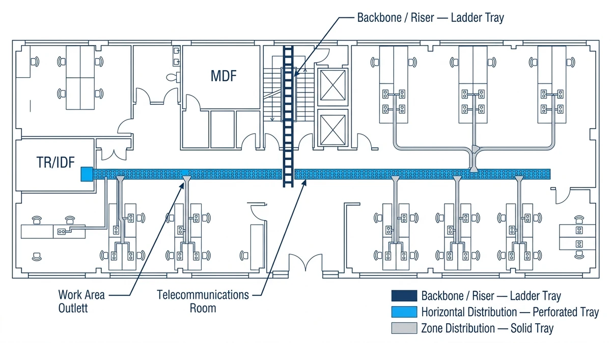
Figure 2. Structured cabling physical pathway zones mapped to cable tray type: ladder tray for backbone and riser runs, perforated tray for horizontal distribution (TR to work area), and solid-bottom tray for zone distribution and sensitive fiber pathways.
[Expert Insight]
– Specifying Class B where Class C is warranted is one of the most common under-engineering errors in structured cabling projects — the cost difference between the two is typically 8–12% on material, but the retrofit cost when trays sag under full load is far higher.
– Hot-dip galvanized steel outperforms pre-galvanized in outdoor or high-humidity environments; the 45 μm minimum zinc coating per ISO 1461 is the threshold that separates adequate from marginal corrosion protection.
– In a 2024 pharmaceutical facility project in Suzhou (12,000 m² clean room), perforated stainless steel trays rated IP54 were specified throughout — the corrosion-resistant finish added roughly 15% to material cost but eliminated the recoating cycles required with standard galvanized steel in that humidity-controlled environment.
– FRP trays are non-conductive, which eliminates grounding requirements in some jurisdictions — worth confirming with the local authority having jurisdiction before specifying.
How to Size a Cable Tray for Structured Cabling
Sizing a cable tray correctly comes down to three measurable parameters: fill capacity, load rating, and span length. Getting any one of these wrong leads to either an oversized system that wastes budget or an undersized one that fails inspection.
Fill Capacity Calculation
Cable tray fill is governed by the cross-sectional area of cables relative to the usable interior area of the tray. Under NEMA VE 1, fill for data cables is limited to 50% of the tray’s interior cross-section — this preserves airflow and allows future additions without a full redesign. A 150 mm wide by 50 mm deep tray offers 7,500 mm² of interior area, meaning the total cable bundle cross-section should not exceed 3,750 mm².
In practice, designing to 40% fill rather than the maximum 50% pays off. In a 2023 campus network upgrade covering six buildings in Guangzhou, the design team used 200 mm wide ladder trays throughout horizontal runs at 40% fill. When a 30% cable count increase was required two years later, no tray sections needed replacement — a measurable outcome that justified the modest upsize at initial installation.
Width selection follows a straightforward process: sum the outer diameters of all cables in the run, apply the fill ratio, then round up to the next standard width. Standard widths are typically 50 mm, 100 mm, 150 mm, 200 mm, 300 mm, or 450 mm. Always account for bend radius requirements at corners — Cat6A cables require a minimum bend radius of 4× the cable outer diameter, which affects usable width through fittings.
For a worked example of this calculation, the cable tray size calculation guide walks through fill ratio, width selection, and load verification step by step.
Load Rating and Span
A typical Cat6A horizontal run weighs approximately 0.08 kg/m per cable. A fully populated 600 mm wide ladder tray carrying 100 cables across a 3 m span generates a distributed load near 8 kg/m — well within Class A limits. But high-density fiber and copper bundles in data center spine runs can reach 85–120 kg/m at full fill, which pushes into Class C or Class D territory.
IEC 61537 sets maximum allowable deflection at L/200. For a 1,500 mm span, that’s 7.5 mm. For a 3,000 mm span, that’s 15 mm. Ladder-style trays in steel generally outperform solid-bottom trays at longer spans due to their higher moment of inertia for equivalent material weight. Wire mesh trays may require support spacing of 1.5 m rather than 3 m to stay within the same deflection limit.
Calculate total cable weight per meter, add a 25% safety margin, then select the load class. If you’re planning for future expansion, sizing up one class costs little upfront and avoids a costly retrofit later. A data center horizontal run carrying 48 Cat6A cables weighs roughly 12–15 kg/m — that’s comfortably Class B, but specifying Class C at the same span costs marginally more and absorbs a significant capacity increase without structural changes.
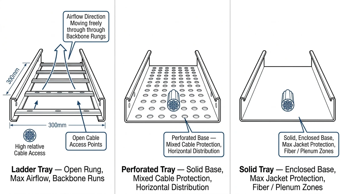
Figure 3. Comparative cross-sections of the three primary cable tray types used in structured cabling: ladder tray (open rung, maximum airflow), perforated tray (solid base with perforations, mixed cable protection), and solid-bottom tray (fully enclosed base, maximum jacket protection).
How to Select the Right Cable Tray for Your Network Infrastructure
With sizing parameters established, selection narrows to matching tray type, material, and configuration to the specific installation environment. This is where engineering judgment and field experience matter most.
Matching Tray Type to Application
Ladder cable trays work best for heavy cable bundles needing maximum airflow over spans of 1.5–3 m. They’re the standard choice for backbone cabling runs in data centers and enterprise campuses. Perforated cable trays balance mechanical protection with moderate airflow and are common in office building horizontal distribution where cables need some physical protection but full enclosure isn’t required. Solid-bottom trays suit sensitive signal cables requiring EMI shielding from below or protection from falling debris.
Wire mesh trays offer the fastest installation and are common in server room deployments where flexibility and visibility matter more than load rating. Their open grid structure makes cable identification and future additions straightforward, which reduces maintenance time in environments where cable changes are frequent.
Environmental and Corrosion Classification
Environment drives material selection more than any other factor. Hot-dip galvanized steel suits most indoor commercial and industrial applications. Stainless steel Grade 316 is the right call for coastal, chemical, or food-processing environments where chloride exposure is continuous. Powder-coated aluminum sits in the middle — at roughly 2.7 kg/dm³ versus steel’s 7.8 kg/dm³, it’s appropriate for most office and data center cable management applications where weight and moderate corrosion resistance are both priorities.
For outdoor cable routing or rooftop pathways, UV-stabilized FRP trays rated to -40°C to +120°C operating range are the appropriate choice. The material cost premium over galvanized steel is typically 20–35%, but it eliminates recoating cycles entirely in aggressive environments.
Fittings, Accessories, and System Completeness
A cable tray system is only as reliable as its fittings. Bends, tees, reducers, and splice plates need to match the tray’s load class and material — mixing grades or manufacturers at connection points is a common source of structural weakness and corrosion. Properly specified cable tray fittings and accessories maintain system continuity and ensure that the load ratings calculated for straight runs hold through direction changes.
Seismic bracing requirements apply in earthquake-prone regions and are increasingly specified in data center projects regardless of seismic zone, as part of broader resilience standards. Verify local code requirements before finalizing support configurations.
Align load class, span, material, and fill ratio before procurement, and tray selection becomes a straightforward engineering decision. For a broader view of how these systems fit into building infrastructure, the electrical cable tray guide covers system integration, grounding, and code compliance in detail.
This article has been updated with explicit source and procurement checks so engineering, EPC, and purchasing teams can verify the recommendations instead of relying only on generic product descriptions. For project use, treat the table below as a starting evidence map and confirm the final requirements against local codes, consultant drawings, and supplier submittals.
Use this source to verify standards, product scope, installation assumptions, or supplier evidence before final specification.
Buyer Verification Checklist
Request drawings that show tray width, depth, side rail profile, bend radius, fittings, and support spacing.
Ask for load tables or engineering assumptions that state test span, load class, and deflection criteria.
Confirm material grade, surface finish, coating method, and corrosion exposure assumptions before comparing prices.
Check whether accessories such as covers, couplers, reducers, clamps, grounding jumpers, and brackets are included.
For EPC or export orders, review packaging, labeling, inspection records, and drawing revision control before shipment.
Frequently Asked Questions
What is the difference between a cable tray and a cable ladder?
A cable ladder is a specific type of cable tray where two longitudinal side rails are connected by transverse rungs, resembling a ladder. The term “cable tray” is the broader category that includes ladder trays, solid-bottom trays, perforated trays, and wire mesh trays — each suited to different load and environmental conditions.
How do I calculate the correct cable tray width for a structured cabling run?
Sum the cross-sectional areas of all cables in the run, divide by the target fill ratio (typically 40–50%), then take the square root to find the minimum tray width and round up to the next standard size. For Cat6A cables with an outer diameter of approximately 7.5 mm, a 300 mm wide tray at 40% fill can accommodate roughly 120–130 cables depending on tray depth.
What load class should I specify for a data center cable tray installation?
For most horizontal distribution zones in data centers, Class B (100 kg/m per IEC 61537) is the practical minimum. High-density spine runs carrying bundled Cat6A and fiber trunk cables at spans exceeding 2 m may require Class C (150 kg/m), particularly when future capacity growth is factored into the design.
How does cable fill ratio affect signal performance in Cat6A runs?
Exceeding the recommended fill ratio increases cable bundle density, which raises ambient temperature around the cables and can increase crosstalk between adjacent pairs. For Cat6A, which operates at frequencies up to 500 MHz, thermal and mechanical stress from overcrowding can degrade insertion loss and return loss margins — issues that may not appear until post-installation channel testing.
What is the maximum span between cable tray supports?
IEC 61537 uses a reference span of 3 m for load class testing, with maximum allowable midspan deflection of L/200. In practice, support spacing of 1.5–2.5 m is common for ladder trays in data center environments, with wire mesh trays often requiring 1.5 m spacing to stay within deflection limits under full cable load.
When should I use stainless steel cable trays instead of galvanized steel?
Stainless steel (Grade 304 or 316) is appropriate when the installation environment involves continuous chloride exposure — coastal facilities, food processing plants, chemical manufacturing, or high-humidity clean rooms. For standard indoor data rooms and commercial buildings, hot-dip galvanized steel with a zinc coating of at least 45 μm per ISO 1461 is generally sufficient and more cost-effective.
Can cable trays be used for both power and data cables in the same installation?
Power and data cables can share a cable tray system, but they are typically separated into dedicated trays or divided sections to prevent electromagnetic interference and comply with applicable wiring codes. Where separation is not possible, maintaining a physical barrier or minimum separation distance between power and data cable bundles is generally required under local electrical installation standards.
Kevin Zheng
Kevin Zheng is a manager linked to Shanghai Xinma Busway & Cable Tray Co., Ltd. He writes technical content on cable tray systems, installation practice, sizing logic, load classes, and related standards for industrial and infrastructure applications.