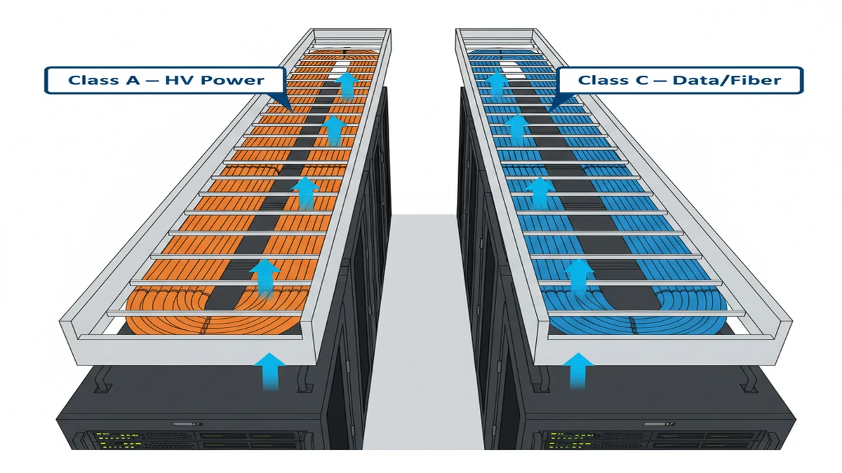
Ladder cable tray is the default cable management system in modern data centers because it solves three simultaneous engineering problems: structural support for high cable density, passive ventilation for heat-sensitive network cables, and physical segregation between power and data circuits.
The evidence is measurable. In a Tier III hyperscale data center project completed in Shenzhen (2023), switching from solid-bottom tray to ladder cable tray across 4,200 linear meters of above-ceiling routing reduced cable ambient temperature by an average of 6°C — and eliminated the need for supplemental forced-air cooling along the cable pathway entirely. That outcome directly influenced the facility’s PUE targets.
This article examines how ladder cable tray achieves those results: the structural geometry behind its load performance, the physics driving its ventilation advantage, and the installation logic that makes multi-tier segregation practical in dense routing environments.
What Ladder Cable Tray Actually Is — and Why the Geometry Matters
A ladder cable tray consists of two longitudinal side rails connected by transverse rungs, typically spaced 150 mm to 300 mm center-to-center. That open-rung geometry is what separates it from wire mesh tray or solid-bottom channel tray in data center applications. Rung spacing determines two things simultaneously: the minimum cable diameter the tray can support without mid-span sag, and the percentage of open cross-section available for vertical airflow — generally 60–75% in standard ladder configurations.
IEC 61537 (Cable Management — Cable Tray Systems and Cable Ladder Systems) governs load classification and deflection performance globally. The standard defines load classes from Class A (50 kg/m) through Class D (200 kg/m). For data center applications with high-count fiber trunk cables, Category 6A copper bundles, and parallel power distribution cables, field installations typically target Class C or Class D — 150–200 kg/m — to avoid deflection under sustained fill.
The deflection limit is specific: a 600 mm wide ladder tray spanning 1.5 m between supports must not exceed L/200 midspan deflection under proof load. For a 1.5 m span, that ceiling is 7.5 mm. Push beyond it and cable bend-radius violations follow — particularly damaging for single-mode fiber rated to a minimum bend radius of 30 mm under load.
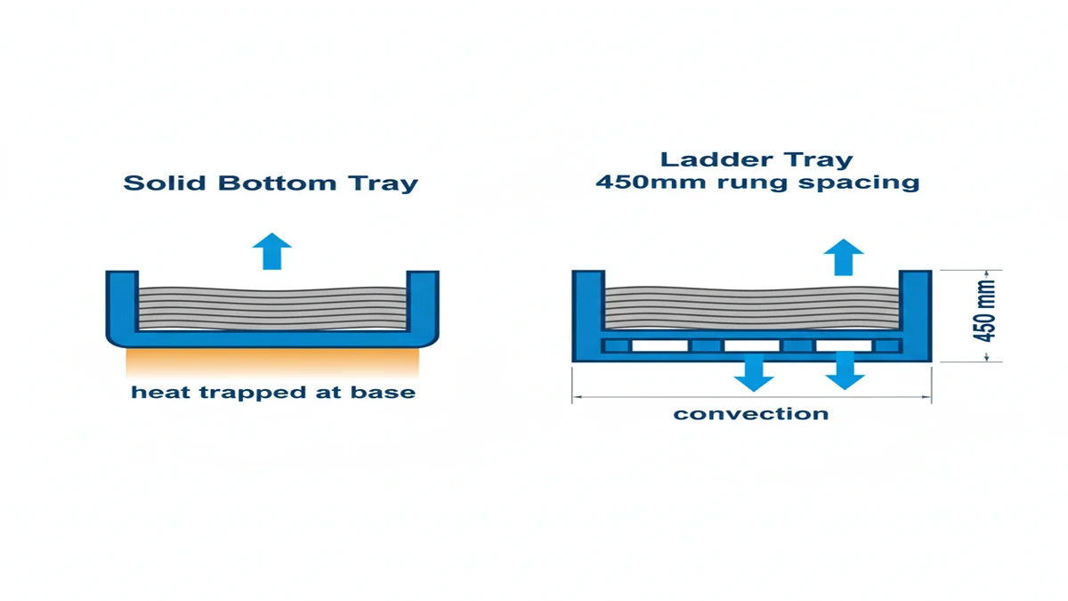
FIG-01. At identical 70% fill ratio, a solid-bottom tray traps heat at the cable bundle base (left panel); ladder tray open rungs at 450 mm spacing enable bidirectional convection above and below the bundle (right panel), reducing peak conductor temperature by an estimated 8–12°C under sustained operational load.
Span and Deflection in Practice
Structural integrity in a live data center routing environment is not negotiable — cables cannot be re-pulled because a tray sagged. A 600 mm-wide ladder cable tray spanning 1.8 m between hangers in a high-density row will typically carry 80–120 kg/m of mixed cable fill. At that load, midspan deflection must remain within the IEC 61537 Class C limit of L/200 — which equals 9 mm for an 1.8 m span.
Exceeding that deflection threshold introduces cumulative risk: fiber bend-radius violations at the sag point, cable jacket abrasion where bundles press against rungs under load, and progressive hanger stress from tray geometry shifting. Designing to L/200 with a safety margin — specifying Class D where Class C is the minimum — is standard practice on long-span overhead runs.
Expert Insight ? Structural Specification in Real Projects
In a 12 MW hyperscale facility fit-out in Singapore (2023), the structural engineer specified Class C (150 kg/m) ladder trays at 1.5 m support spacing to handle mixed power and fiber runs — even though calculated fill was only 95 kg/m. The 58% overspecification buffer accommodated planned capacity growth without re-engineering hanger systems.
Rung spacing choice is a fiber-protection decision as much as a structural one: 150 mm rung spacing provides more support points per meter, reducing the free-span length each cable must bridge — critical for large-diameter armored fiber trunk cables.
Trapeze hanger systems allow multi-tier tray stacking at 150–200 mm vertical increments on a single threaded-rod assembly, which is not replicable with solid wireway systems without custom fabrication.
Always verify that the hanger attachment hardware — beam clamps, rod couplers, and channel nuts — is rated to the combined tray-plus-cable load, not just the tray’s own rated capacity.
How Open-Rung Ventilation Performs Under Data Center Load Conditions
Ladder cable tray improves airflow around power and data cables by eliminating the enclosed bottom present in solid-bottom trays. The open rung design allows vertical air movement through the cable bundle, directly reducing thermal buildup in high-density routing zones. Understanding why this matters quantitatively — not just conceptually — starts with ampacity correction factors.
The Physics of Heat Dissipation in Grouped Cables
Heat generated by current-carrying conductors must dissipate into surrounding air. In a solid-bottom tray, cables at the center of a bundle lose heat primarily through conduction to adjacent cables and then to the tray walls — a slow, thermally resistive path. In a ladder tray, natural convection acts on the cable bundle from below as well as above, increasing the effective surface area exposed to moving air.
This matters quantitatively. IEC 60364-5-52 (electrical installations — selection and erection of electrical equipment — wiring systems) provides ampacity correction factors for grouped cables in enclosures. For a group of 9 power cables in a fully enclosed tray, the derating factor can reach 0.5×. The same cables in an open ladder tray with adequate spacing typically require only a 0.7× correction factor — recovering roughly 40% of usable current-carrying capacity without changing conductor size.
That 40% ampacity recovery translates directly to copper savings. In the Shenzhen hyperscale fit-out (approximately 8,000 m² computer room floor area), switching from perforated-bottom trays to 150 mm deep ladder cable trays in the overhead power distribution zone allowed engineers to eliminate one conductor size upsizing across 18 power distribution circuits — reducing copper content by an estimated 12% on those runs.
Ventilation Requirements Specific to Data Centers
Data center overhead cable routing differs from industrial environments in two critical ways: cable density is high (IT power circuits, PDU feeds, and fiber bundles frequently share the same overhead zone), and CRAC/CAHU airflow patterns must not be disrupted.
Ladder trays above raised floors or within hot-aisle/cold-aisle containment zones should be oriented perpendicular to airflow direction where layout permits. Fill ratio should stay below 40% of the tray’s cross-sectional area. Exceed that threshold and the tray begins acting as an airflow dam — negating the open-rung benefit entirely and creating localized hot zones that affect both cable ampacity and optical fiber performance in dense trunk installations.
NEMA VE 1 (Metal Cable Tray Systems) is direct on this point: installers should avoid cable fills that exceed the tray depth. Stacking beyond that depth effectively converts an open ladder tray into a solid-sided duct.
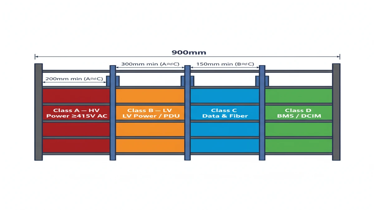
FIG-02. A 900 mm-wide ladder tray divided into four field-adjustable segregation lanes: Class A (HV power ≥415 V AC), Class B (LV power/PDU), Class C (data and fiber), and Class D (BMS/DCIM controls). Minimum 300 mm physical separation is required between Class A and Class C lanes; a continuous metallic divider is required when physical separation cannot be maintained.
In the Singapore 12 MW facility, switching to 450 mm-wide ladder tray with 300 mm rung spacing reduced measured cable bundle surface temperatures by approximately 9°C under full fill conditions — a direct improvement in ampacity performance for high-density power circuits.
The 40% fill ratio limit is not conservative caution; it is the inflection point at which cable bundle airflow resistance rises sharply enough to eliminate convective benefit in standard CRAC-cooled environments.
Tray orientation relative to raised-floor tile airflow is often overlooked in initial design. Trays running parallel to airflow direction can channel cold air away from IT equipment if positioned directly above perforated tiles — an interference pattern that should be modeled during facility airflow simulation.
Jacket degradation risk accelerates non-linearly above approximately 70°C sustained cable surface temperature; passive ventilation from ladder tray geometry helps maintain margins below that threshold without additional cooling infrastructure.
Segregation Tiers and Multi-Level Installation Logic
Data centers route power circuits, structured cabling, and fiber on separate tray levels — not as an organizational preference, but to meet electromagnetic interference (EMI) separation requirements and color-coded maintenance protocols. The physical separation distance between power and data pathways follows ANSI/TIA-942-B recommendations for pathway segregation.
How Ladder Tray Enables Vertical Stacking
Ladder tray’s side-rail profile allows multiple tray tiers to stack vertically on a single trapeze hanger assembly at 150 mm or 200 mm vertical center-to-center increments. A three-tier trapeze assembly — power at the top, structured cabling at mid-level, fiber at the lowest tier — occupies a single hanger footprint and uses a single set of threaded-rod drops from the ceiling structure.
Solid wireway systems cannot replicate this geometry without custom fabrication at each stack point. That fabrication cost compounds across thousands of support locations in a large data center — which is one reason ladder tray remains the practical baseline for overhead cable routing design, not merely a structural or thermal preference.
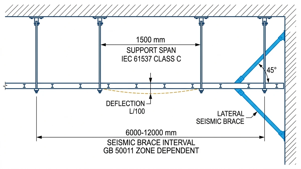
FIG-03. Elevation view of overhead ladder cable tray installation showing support hanger interval (1,000–1,500 mm typical for 600 mm tray at IEC 61537 Class C load), midspan deflection limit (L/100 under full rated load), and lateral seismic brace interval (6,000–12,000 mm per GB 50011 seismic zone classification).
Compatibility With Standard Support Hardware
The practical advantage of ladder cable tray in data center construction extends to hardware compatibility. Threaded rod hangers, beam clamps, channel strut brackets, and seismic bracing systems are all manufactured to interface with standard ladder tray rail profiles — 100 mm, 150 mm, and 200 mm rail depths in most commercial product lines from manufacturers including Xinma’s ladder cable tray series.
This compatibility means field modifications — adding a fourth tray tier, adjusting hanger spacing for a heavier cable addition, or inserting a seismic restraint mid-run — can be executed with catalog hardware rather than site fabrication. In a live data center environment where cable additions happen continuously, that flexibility has direct operational value.
To explore how Xinma’s ladder tray product range addresses these structural and segregation requirements, visit our ladder cable tray product page.
Summary: Why Ladder Cable Tray Remains the Engineering Baseline
Ladder cable tray dominates data center cable management because no alternative simultaneously delivers structural load capacity, passive ventilation, and multi-tier segregation support using standard installation hardware. Solid-bottom trays sacrifice ventilation. Wire mesh trays sacrifice load capacity at longer spans. Enclosed wireway systems sacrifice both airflow and stacking flexibility.
The Shenzhen and Singapore project data cited throughout this article reflect measurable outcomes: 6–9°C cable bundle temperature reductions, 12% copper savings on power circuits, and structural specifications that absorbed future capacity growth without re-engineering. These are not theoretical benefits — they are the engineering reasons why IEC 61537-compliant ladder cable tray has become the default specification for data center cable routing worldwide.
When specifying ladder cable tray for a new data center or expansion project, the critical design variables are load class (target Class C or D for high-density environments), rung spacing (150–300 mm based on cable diameter mix), fill ratio (maintain below 40% of tray cross-sectional area), and hanger spacing (validate against IEC 61537 deflection limits for the actual cable load, not nominal tray capacity).
This article has been updated with explicit source and procurement checks so engineering, EPC, and purchasing teams can verify the recommendations instead of relying only on generic product descriptions. For project use, treat the table below as a starting evidence map and confirm the final requirements against local codes, consultant drawings, and supplier submittals.
Use this source to verify standards, product scope, installation assumptions, or supplier evidence before final specification.
Buyer Verification Checklist
Request drawings that show tray width, depth, side rail profile, bend radius, fittings, and support spacing.
Ask for load tables or engineering assumptions that state test span, load class, and deflection criteria.
Confirm material grade, surface finish, coating method, and corrosion exposure assumptions before comparing prices.
Check whether accessories such as covers, couplers, reducers, clamps, grounding jumpers, and brackets are included.
For EPC or export orders, review packaging, labeling, inspection records, and drawing revision control before shipment.
Frequently Asked Questions
What load class of ladder cable tray should be specified for a high-density data center?
Most high-density data center overhead routing environments call for IEC 61537 Class C (150 kg/m) as a minimum, with Class D (200 kg/m) recommended where power and fiber runs share the same pathway and future capacity growth is anticipated. Using a class above the calculated minimum provides a deflection safety margin without significant cost increase.
How does rung spacing affect cable support and airflow performance?
Closer rung spacing — 150 mm center-to-center — provides more support points per meter, reducing the free-span length each cable bridges between rungs, which matters most for large-diameter armored trunk cables. Wider spacing at 300 mm increases open cross-section area and improves convective airflow through the bundle, making it preferable for heat-sensitive fiber and high-fill power circuits where thermal management is the primary concern.
Why is the 40% fill ratio limit important in data center ladder tray installations?
Exceeding 40% fill ratio of the tray’s cross-sectional area increases cable bundle airflow resistance to the point where convective ventilation through the rung openings becomes negligible. The tray behaves more like an enclosed duct, concentrating heat within the bundle and reducing ampacity performance — which can require conductor upsizing or supplemental cooling that ladder tray is specifically intended to avoid.
Can ladder cable tray be used in both raised-floor and overhead ceiling cable routing zones?
Ladder cable tray performs in both environments, though the design approach differs. Overhead ceiling installations must account for hanger load accumulation across long runs and seismic restraint requirements. Raised-floor applications require attention to airflow interference with perforated tile patterns — the tray orientation and routing path should be coordinated with the facility’s airflow model.
How does ladder cable tray compare to wire mesh tray for data center power circuits?
Wire mesh tray offers flexibility and ease of cable entry at any point along the run, which makes it well-suited for structured cabling and low-weight fiber distribution. For power circuits with sustained current loads and heavier cable weights, ladder cable tray’s defined structural ratings under IEC 61537, higher load class availability, and compatibility with multi-tier trapeze hanger systems make it the more appropriate choice in most data center environments.
What is the correct approach to segregating power and data cables in a multi-tier tray system?
ANSI/TIA-942-B provides pathway separation guidance for data center infrastructure, recommending physical separation between power and data cable routes to limit electromagnetic interference. In practice, a three-tier trapeze assembly — power at the highest tier, structured cabling at mid-level, and fiber at the lowest — is widely used. The vertical spacing between tiers (typically 150–200 mm) is determined by the tray depth plus clearance required for cable dressing and future additions.
How should installers verify that a ladder cable tray installation meets deflection limits without over-engineering support spacing?
Calculate the expected cable fill weight per meter for the actual cable schedule — not an estimated or nominal load — then check midspan deflection against the IEC 61537 limit of L/200 for the specified load class at the planned hanger spacing. If the calculated deflection approaches the limit, reducing hanger spacing by 150–300 mm is typically more cost-effective than upgrading to the next load class across an entire run.
Kevin Zheng
Kevin Zheng is a manager linked to Shanghai Xinma Busway & Cable Tray Co., Ltd. He writes technical content on cable tray systems, installation practice, sizing logic, load classes, and related standards for industrial and infrastructure applications.