Busbar electrical systems distribute power through copper or aluminum conductors arranged as a controlled current path. The term can describe a simple busbar inside switchgear, or a complete enclosed busbar trunking system used through a plant, data center, commercial riser, or electrical room. Engineers should define the scope before comparing ratings, routes, installation labor, and supplier proposals.
What Is an Electrical Bus Bar?
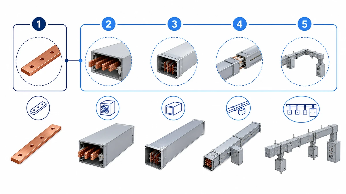
An electrical bus bar is a conductive bar, strip, or profile used to collect current from one source and distribute it to several downstream circuits. It is usually made from copper or aluminum because both materials can carry high current with predictable resistance, heat rise, and connection behavior when correctly sized.
A busbar electrical system routes power through enclosed conductors between source equipment, distribution boards, and load zones.
Inside equipment, a busbar may be only the conductor. It can sit in switchgear, panelboards, transformers, UPS cabinets, battery systems, motor control centers, or main distribution boards. In building and industrial distribution, the same word is sometimes used more broadly for an enclosed route that includes conductors, insulation, housing, joints, supports, and tap-off interfaces.
That difference matters in procurement. A buyer asking for “busbar electrical” parts may need replacement conductors for a panel. A project engineer asking for a busbar trunking system usually needs a factory-built power route with drawings, ratings, accessories, installation instructions, and test documents.
Busbar, Busbar Trunking, Busway, and Bus Duct
Busbar is the base term. Busbar trunking, busway, and bus duct usually describe a complete enclosed assembly built around busbars. The names overlap by market and specification style, but the product boundary should be confirmed before quotations are compared.
For a practical definition of the enclosed system, use the separate Xinma guide to what bus duct means in projects. In this article, busbar electrical starts from the conductor concept, then narrows into busbar trunking and busway as engineered distribution systems.
The distinction changes the checklist. A bare busbar is judged by material, section size, spacing, insulation support, plating, and connection surfaces. A busbar trunking system is judged by rated current, voltage, short-circuit withstand, temperature rise, IP protection, joint design, tap-off design, route geometry, supports, and documentation. EPC and MEP teams should align the single-line diagram, route drawing, BOQ, and supplier scope so the same system is being priced.
How Busbar Trunking Systems Work
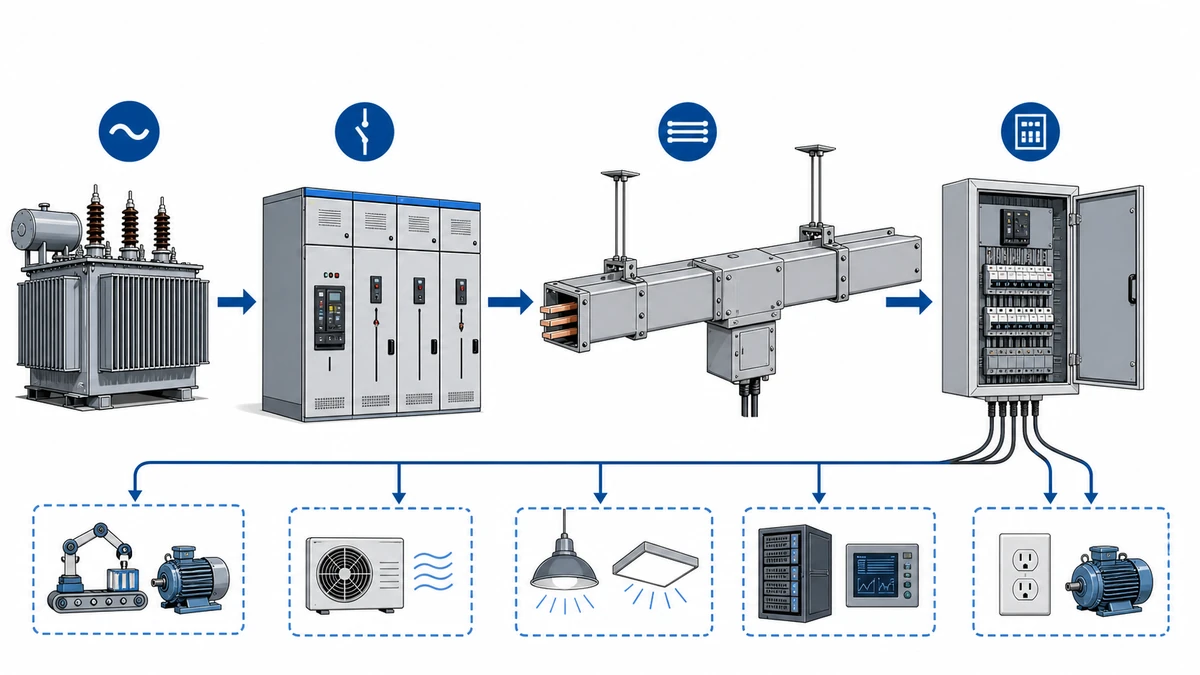
A busbar trunking system carries power through enclosed conductors arranged by phase, neutral, and protective earth requirements. The current path may run from transformer to switchboard, switchboard to a riser, a riser to floor distribution, or an overhead route to plug-in load points.
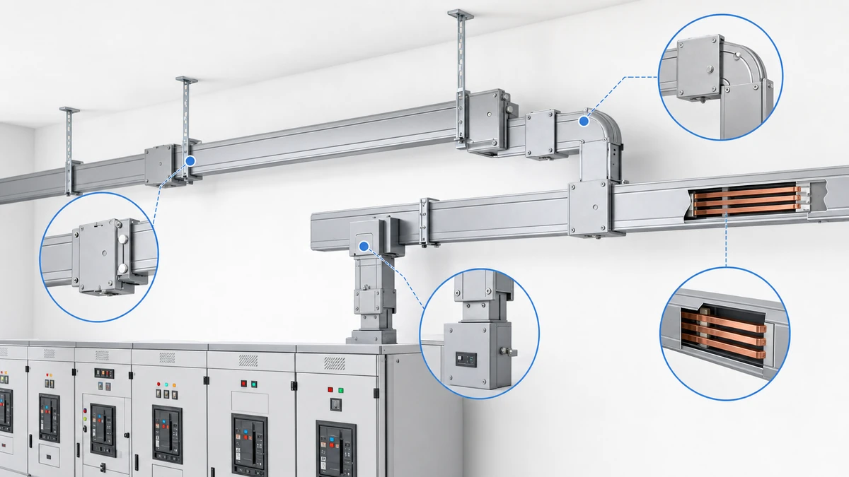
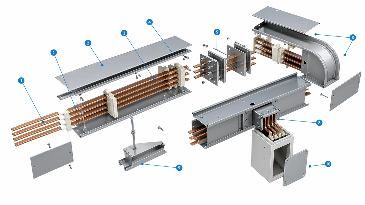
The main parts are straightforward: copper or aluminum conductors, insulation, enclosure, joints, fittings, tap-off units, end feeds, supports, and covers. Conductor cross-section and material affect current capacity and voltage drop. Spacing and insulation affect dielectric performance. Enclosure design affects mechanical protection, heat dissipation, corrosion resistance, and installation alignment.
Busbar can describe the conductor, while busway, bus duct, and busbar trunking usually describe the enclosed system.
Joints need special attention because they combine electrical contact and mechanical alignment. A route can have correct catalog ratings but still create maintenance risk if joint packs sit behind ceilings, walls, ducts, or inaccessible equipment. Good drawings identify joint locations, torque requirements, access covers, tap-off positions, supports, and inspection clearance before release for manufacturing.
For vertical risers, the mechanical question is as important as the electrical one. The support stack must handle section weight, building movement, installation tolerances, and later inspection. For long horizontal routes, engineers should check hanger spacing, thermal expansion, route slope if any, and whether lifting access is available for each factory section.
Feeder busway and plug-in busway serve different purposes. Feeder busway moves power point to point with few intermediate outlets. Plug-in busway adds planned tap-off points so loads can be moved or expanded along the route. Data halls, production lines, workshops, and commercial floors often evaluate plug-in routes when future equipment changes are likely.
Project teams should also define where busbar trunking stops and downstream cabling starts. End-feed units, tap-off boxes, protective devices, metering, outgoing cable glands, and fire-stopping interfaces are often split between supplier, installer, and switchgear contractor. Clear responsibility avoids site arguments after material arrives.
Where Busbar Systems Beat Cable, and Where They Do Not
Busbar electrical systems fit best where the route is high-current, dense, repetitive, or space constrained. Typical examples include transformer-to-switchboard feeders, high-rise risers, factory production lines, data center power distribution, large commercial electrical rooms, hospitals, airports, and rail/transit facilities.
Busbar trunking systems combine conductors, insulation, enclosure, joints, supports, fittings, and optional tap-off units.
The decision is not simply busbar versus cable. It is a route, labor, access, heat, and future-change decision. Busbar trunking can reduce cable bundle volume, reduce on-site terminations, and make tap-off positions more organized. It can also be easier to inspect when joints and covers remain visible.
Cable distribution remains better for many small loads, irregular routes, control circuits, instrumentation, long outdoor corridors, and systems where individual cables need to be changed often. A cable tray network can be more flexible when many circuits of different types need separation by voltage, function, fire zone, or routing priority.
A useful selection method is to separate feeder duty from final distribution. Busbar trunking may be the cleaner answer for a high-current main path, while cable tray remains the better answer for scattered branch circuits. Hybrid layouts are common in real projects because power density changes from transformer room to riser, floor, corridor, and equipment zone.
In an anonymized East China electronics manufacturing retrofit in 2023, changing a 180-meter production feeder route from multiple parallel cable runs to plug-in busway reduced the planned shutdown window by about two days. In a Southeast Asia commercial complex review in 2024, prefabricated busbar trunking sections reduced planned on-site termination points by roughly 30% compared with the preliminary cable distribution plan. These are project-specific results, not universal guarantees, but they show why route geometry and labor planning matter.
Selection Checks Before Specifying Busbar Electrical Systems
Start with the load schedule, service voltage, continuous current, demand factor, spare capacity, ambient temperature, and available fault current. Then confirm whether the selected busbar trunking system has suitable current rating, short-circuit withstand, temperature-rise evidence, enclosure protection, conductor material, and installation orientation.
For rating work, do not accept a catalog ampere number by itself. Review conductor material, enclosure design, ambient assumptions, route orientation, harmonic load if relevant, neutral sizing, and future expansion. The Xinma guide to busway current rating selection is useful when project load profiles are not simple.
Selection should connect electrical ratings, route geometry, environmental protection, installation access, and supplier documentation.
International busbar trunking specifications commonly reference IEC 61439-6 busbar trunking systems. The project should still verify the exact edition, scope, product family, test evidence, and manufacturer documentation. If ingress protection is important, engineers may also reference IEC 60529 concepts for IP classification, but they should not treat an IP code as a substitute for thermal, fault, and installation verification.
For North American or mixed-standard projects, UL 857 may also appear in specifications for busway. That does not make one standard interchangeable with another. The procurement package should name the required standard basis, testing evidence, voltage class, current rating, enclosure type, and any local authority requirements before suppliers prepare the final technical offer.
Route geometry should be checked before procurement. Long horizontal runs, vertical risers, elbows, offsets, transformer interfaces, switchgear flanges, expansion sections, wall penetrations, and tap-off schedules all affect the final package. Supplier documents should include route drawings, section list, joint details, support plan, installation method, packing list, test records, and maintenance guidance.
Xinma Product-Ecosystem Fit and Procurement Notes
Shanghai Xinma manufactures busway and busbar trunking systems as part of a wider product ecosystem that also includes cable tray, fittings, accessories, and seismic bracing components. For project teams, the value is not a generic ranking claim. It is practical coordination: compatible model codes, finishes, support geometry, clamp or tap-off access, BOM consistency, repeated delivery logic, and site inspection consistency across related electrical pathways.
When a project combines busway and busbar trunking systems with tray routes or structural support requirements, early coordination helps avoid late changes around brackets, wall penetrations, joint access, and maintenance zones. In seismic-design regions or large MEP corridors, compatible seismic bracing should be checked with the route, support loads, ceiling services, and inspection access before fabrication.
A coordinated package also improves replacement and expansion work. If labels, section codes, finish systems, support families, and accessory schedules follow one logic, site teams can identify the right part faster during receiving inspection, installation, and later modification. That is especially useful when busbar, tray, and bracing packages are delivered in separate lots.
For procurement, issue drawings and schedules that define rated current, voltage, poles, neutral size, PE arrangement, fault level, IP expectation, orientation, ambient conditions, tap-off units, feeder sections, supports, accessories, and interface responsibility. Ask suppliers to map the BOM back to the route drawing so receiving inspection and site installation can be checked without guesswork.
Frequently Asked Questions
What is an electrical bus bar used for?
An electrical bus bar collects and distributes current inside equipment or an enclosed distribution route. It is used in switchgear, panelboards, transformers, UPS systems, battery systems, motor control centers, busway, and busbar trunking systems.
Is busbar trunking the same as busway?
In many building and industrial projects, yes. Busbar trunking, busway, and bus duct often refer to an enclosed modular power distribution system using busbars. Engineers should still confirm the exact scope, accessories, ratings, and installation documents.
How do engineers size a busbar electrical system?
Engineers start with load current, voltage, demand factor, spare capacity, ambient temperature, conductor material, route orientation, fault current, neutral requirements, and future tap-off needs. The final selection should be checked against verified manufacturer data rather than a catalog current number alone.
Are copper busbars better than aluminum busbars?
Copper carries more current in a smaller section, while aluminum can reduce weight and cost when correctly sized. The better choice depends on space, thermal performance, mechanical design, connection method, budget, and maintenance preference.
What should buyers check before approving a busbar proposal?
Buyers should verify the electrical schedule, route drawings, current rating, short-circuit withstand data, conductor material, enclosure type, joint design, tap-off schedule, supports, accessories, packing list, test documents, and installation responsibilities.
Kevin Zheng
Kevin Zheng is a manager linked to Shanghai Xinma Busway & Cable Tray Co., Ltd. He writes technical content on cable tray systems, installation practice, sizing logic, load classes, and related standards for industrial and infrastructure applications.