Address
304 North Cardinal St.
Dorchester Center, MA 02124
Work Hours
Monday to Friday: 7AM - 7PM
Weekend: 10AM - 5PM
Address
304 North Cardinal St.
Dorchester Center, MA 02124
Work Hours
Monday to Friday: 7AM - 7PM
Weekend: 10AM - 5PM
Get premium quality cable management systems directly from the manufacturer.
Fill out the form below to receive our catalog and pricing.
Seismic bracing failures in MEP systems rarely trace back to a single bad part. They trace back to a selection process that treated bracing as a generic hardware add-on rather than a coordinated restraint assembly sized to a specific load path, application type, and structural anchor condition. For EPC and MEP engineers specifying cable tray, pipe, or duct installations in seismically active zones—or in facilities where local codes require restraint regardless of zone—component selection starts before any catalog page opens.
This guide works through the decisions in sequence: application match, load path definition, strut and connector sizing, finish selection for the installation environment, and procurement verification. Each section targets the specific inputs that prevent mismatched hardware or non-compliant brace spacing from reaching site.
The full XMQJ seismic bracing system covers all three application types with application-specific clamp options, strut channel profiles, connectors, and anchors built for coordinated takeoff from a single source.
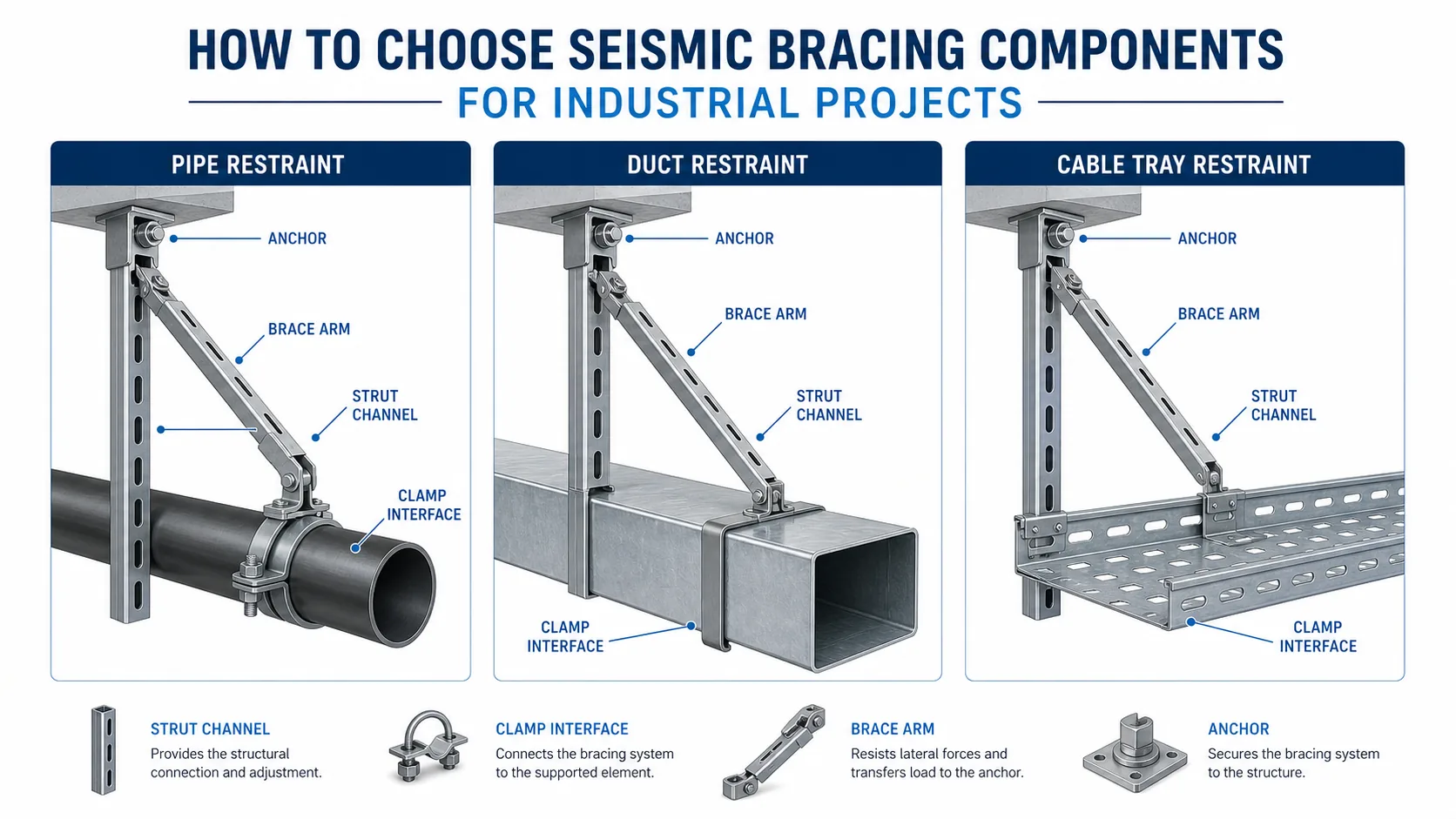
Seismic bracing is not a single catalog item. It is an assembly: clamp body, strut channel arm, connector fittings, and structural anchor, all working as a chain. The geometry of that chain changes depending on whether the restrained element is a pipe, an HVAC duct, or a cable tray system carrying power or data cables.
Pipe and sprinkler restraint uses a saddle-style or ring clamp that wraps the pipe OD. The brace arm connects directly to the clamp body, and the load transfers in a predictable line from the pipe centerline through the clamp to the strut. Brace angle, clamp bore size, and pipe schedule all affect whether the assembly meets the design load without slip or clamp deformation.
HVAC duct restraint introduces a different challenge: duct perimeter governs the trapeze or sway-brace clamp width, and rectangular ducts produce uneven load distribution across the clamp contact surface. A duct brace also needs to address both lateral sway and, depending on duct length and direction changes, longitudinal force along the duct run. Engineers specifying duct restraint should confirm whether the project requires lateral-only or combined lateral-plus-longitudinal assemblies before selecting hardware.
Cable tray sway restraint works differently from both. The clamp interfaces with a tray side rail or rung, not a round or rectangular profile with a defined perimeter. Tray width, rail height, and the tray’s own structural capacity under combined cable fill and seismic load all enter the calculation. A wide ladder tray carrying a heavy cable bundle behaves structurally unlike a narrow solid tray with light instrumentation cable—the brace spacing and clamp body selection must reflect that difference.
Locking the application type at the start of takeoff prevents the most common mismatch: a clamp specified for one application installed on another, where the contact geometry or load transfer angle does not match the design assumption. XMQJ’s component range covers all three application paths with dedicated clamp options for each, allowing the takeoff to stay consistent from clamp selection through anchor specification.
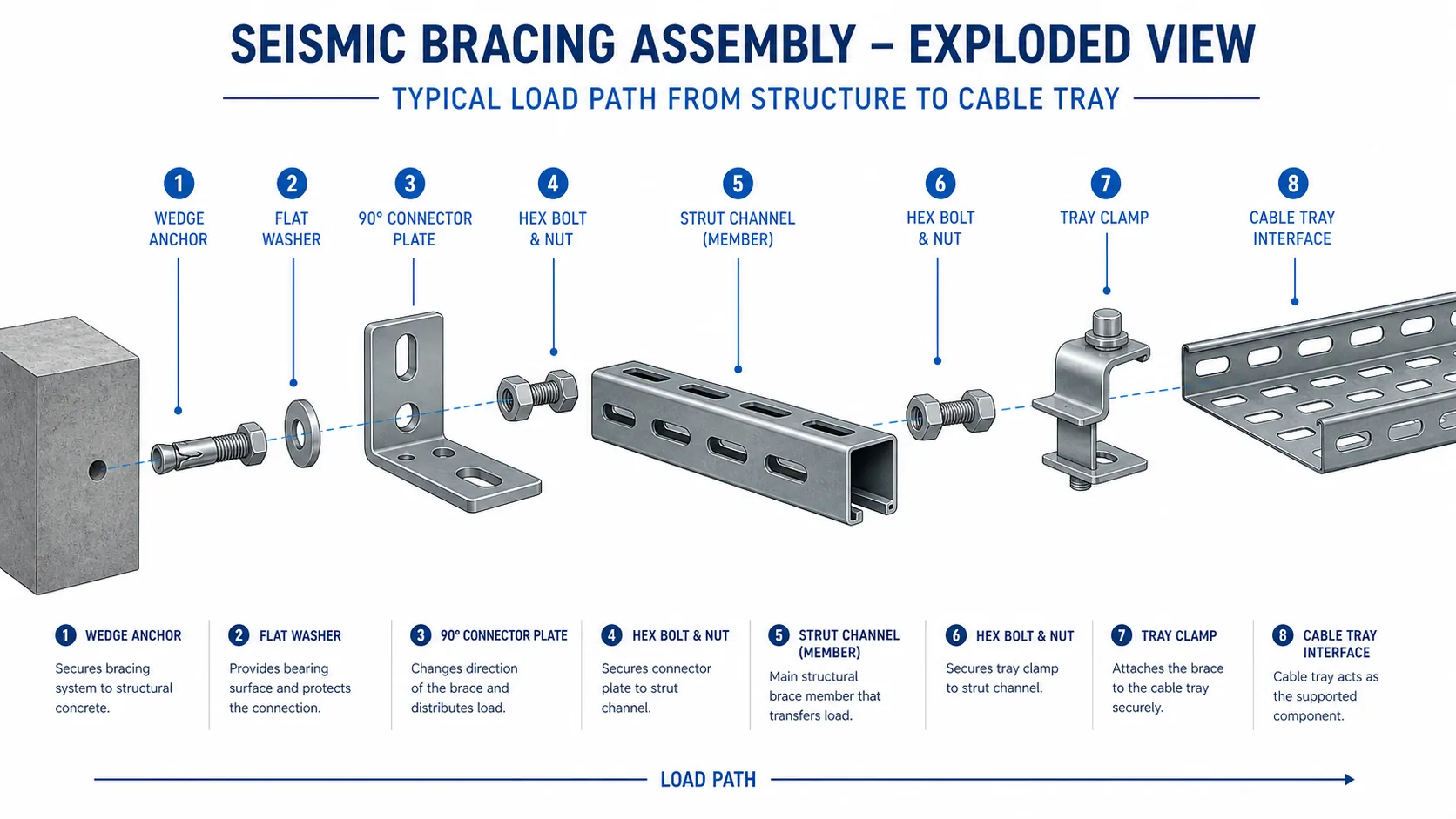
Before selecting any individual component, trace the complete load path from the MEP element to the structure. Seismic force originates at the pipe, duct, or cable tray during a seismic event, transfers through the clamp into the strut channel, passes through the connector fitting, and terminates at the structural anchor embedded in concrete or bolted to a steel beam. Every joint in that chain must be sized for the same design force. Specifying a heavy-duty strut channel while using an undersized 90° connector bracket—or vice versa—creates a weak link that invalidates the restraint assembly regardless of how robust the individual parts appear on paper.

Lateral bracing resists transverse horizontal force—movement perpendicular to the tray run. Longitudinal bracing resists force along the run direction. On most industrial cable tray installations, both directions are required, though their spacing intervals differ. Lateral braces are typically placed at closer intervals; longitudinal braces are required at defined distances along the run and at every significant change in direction, such as horizontal elbows or tee intersections.
Brace spacing is not a fixed table value—it is a calculated output derived from the site’s seismic zone classification, the weight of the supported cables, the tray span configuration, and the structural landing points available. The engineer of record must confirm spacing from seismic load inputs. ASCE/SEI 7 (ASCE 7 standard) is the standard framework for seismic load determination on US and internationally referenced projects; the design-basis input comes from site-specific spectral acceleration data, not a generic zone map pulled from a product catalog.
XMQJ’s strut channel range covers single C-channel and back-to-back double-channel profiles. The choice between them follows load and brace-arm geometry:
Brace arm length also affects load path efficiency. A longer arm increases the moment transferred to the anchor, which may require a larger anchor diameter or a transition from a single to double strut profile. Engineers should verify this interaction before finalizing the bill of materials, particularly on runs with variable ceiling heights or obstructions that force non-standard brace angles.
Coordinate brace landing points with your support spacing layout early. As covered in XMQJ’s cable tray installation guide, support intervals and structural penetration points need to be resolved at the layout stage—the same discipline applies when seismic brace locations are added to the tray support schedule.
Once the load path is mapped, component selection becomes a sequential hardware decision—not a catalog browse. Each element from tray bracket to anchor must be confirmed against the same design load before procurement closes.
Select channel gauge and profile based on brace arm length and design load, not installation convenience. Standard single C-channel (typically 41 × 41 mm or 41 × 21 mm profile) handles lighter tray sway restraint on short brace arms. Back-to-back double channel is the correct choice for multi-trade MEP corridors, longer brace arm spans, or installations where combined lateral and longitudinal loads act on the same brace point. Verify that the channel gauge matches the load rating published in the manufacturer’s load table for the configured span—do not interpolate between sizes without recalculating. XMQJ’s seismic bracing system covers both single and double-channel configurations with corresponding component model data.
The clamp body must match the tray flange width or pipe outside diameter exactly. For cable tray, confirm the clamp seats on the tray side rail without bearing on cable fill—improper seating shifts load into the tray body rather than the structural member. For pipe, saddle-type clamps must contact the pipe barrel uniformly; verify the clamp model against the pipe schedule and outside diameter, not just nominal size. Consult the cable tray accessories range for compatible tray clamp options when integrating restraint hardware with existing tray runs.
90° bracket connectors transfer load from the strut arm into the structural landing point. Confirm the connector’s published load rating covers the calculated reaction at that node. For concrete slab attachments, expansion anchors require minimum embedment depth and edge distance verified against the substrate—confirm concrete compressive strength before specifying anchor type or torque value. For steel beam attachments, beam clamps must match flange thickness and width; verify the clamp’s published beam flange range before ordering.
Use the fastener grade specified by the connector or clamp manufacturer. Substituting a lower-grade bolt to match site inventory invalidates the assembly’s published load rating. Stainless steel or hot-dip galvanized hardware is required in corrosive or outdoor environments; mixing finishes in a single assembly accelerates galvanic degradation at contact points. Review finish compatibility against your project’s exposure classification. XMQJ’s cable tray fittings documentation notes finish pairing requirements applicable to combined tray and bracing assemblies.
Install structural anchors first and verify torque before hanging any strut or clamp. Sequence matters: anchoring to an unsupported strut frame while it carries live load risks misalignment at the connector joint. Field inspection should confirm anchor torque records, clamp seating on the tray rail or pipe barrel, and that every fastener is tightened to the manufacturer’s specified torque value—not estimated by feel. Flag any substituted component for engineering review before the inspection sign-off; undocumented substitutions are the most common source of post-installation compliance failures on MEP bracing packages.
A correctly specified seismic bracing assembly can still underperform if installation deviates from the design intent. The most common field failures do not come from wrong product selection—they come from correct components installed incorrectly.
Incorrect brace angle. Seismic brace rods and strut arms are effective within a defined angular range relative to the structural anchor point. Installing a brace at a shallower angle to clear a duct or beam reduces the horizontal load component the brace can resist. Verify brace angles against the design drawings before final tightening.
Under-torqued or mispositioned anchors. Expansion anchors into concrete require a minimum embedment depth and edge distance to reach rated pullout capacity. Anchors placed too close to slab edges or penetrations, or not driven to the specified embedment, will not develop the load path calculated in the design. Require anchor installation records on projects where the structural engineer of record has specified anchor type and embedment.
Mixed finishes creating galvanic contact. Pairing hot-dip galvanized strut with plain steel hardware, or stainless clamps against untreated mild steel strut, accelerates localized corrosion at contact points. All components within an assembly should carry the same finish specification. XMQJ’s seismic bracing system supplies matched finish sets—HDG, epoxy, or stainless—to eliminate this risk at the procurement stage.
Omitting longitudinal bracing at direction changes. Cable tray runs that change direction create an anchor point for longitudinal force from both sides. Omitting a longitudinal brace at these nodes is a frequent oversight during installation that the design drawings may not flag clearly. Cross-check the brace layout against any direction change, offset, or tee in the cable tray routing plan.
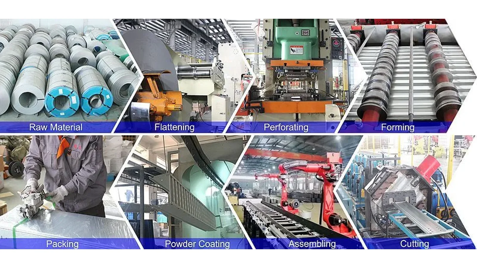
Batch-to-batch dimensional consistency matters when seismic bracing components are ordered across multiple project phases. Request dimensional inspection records covering strut slot pitch, plate hole pattern, and channel wall thickness for each production batch. Xinma operates under ISO 9001 certification with factory-direct supply, which allows procurement teams to trace material and finish records to a single manufacturing source rather than managing multiple sub-supplier chains. For projects requiring phased delivery—common in metro, data center, or multi-building industrial EPC packages—confirm that lead time commitments cover both standard and custom-length strut channel, since site-cut channel introduces variability that factory-cut stock eliminates.
For hardware-level accessory traceability, cross-reference with cable tray accessories supply documentation, which follows the same batch inspection workflow used for seismic hardware.
Finish selection is a procurement decision that must match both the installation environment and the project specification—not a field adjustment. For standard indoor mechanical rooms, pre-galvanized (Z275 or equivalent) strut channel and fittings are generally acceptable. For coastal, tunnel, or process-chemical environments, hot-dip galvanized (HDG) or 316 stainless steel components are required. Epoxy-coated options apply where condensation cycling or mild chemical exposure is present but full immersion is not.
Verify that the finish applies to every component in the brace assembly: strut channel, base plate, connectors, clamps, threaded rod, and anchor. Mixed-finish assemblies can introduce galvanic corrosion at contact points, particularly where stainless fasteners contact carbon-steel channel in a wet environment. Request a finish confirmation on the bill of materials line-by-line, not just a cover-page statement.
Dimensional tolerance matters at the installation interface. Confirm that strut slot pitch, flange width, and back-to-back channel depth match the connector and clamp models specified. XMQJ’s seismic bracing system components are dimensionally coordinated across the product range—channel profile, base plate, and clamp geometry are matched to eliminate field interference, but verify model numbers against the project BOM before shipping approval.
For projects requiring third-party documentation, request material test certificates (MTCs) to confirm base steel grade, coating weight test reports per the applicable HDG or pre-galv standard, and the supplier’s ISO 9001 quality management certificate. IEC 61537, which governs cable management systems including cable tray and associated support hardware, provides dimensional and performance verification methods that procurement teams can use as a reference framework when reviewing supplier documentation—consult the IEC 61537:2023 publication page for current edition details.
Check lead time against the project IFC drawing schedule. Seismic bracing components for large MEP corridors often ship as kitted packages; confirm that anchor hardware is included or locally sourced with matching load ratings. For cable tray runs requiring seismic restraint, coordinate the brace BOM alongside your cable tray accessories and cable tray fittings orders to consolidate supply and reduce site logistics risk.
Lateral bracing resists horizontal force perpendicular to the tray run direction and is installed at intervals determined by the seismic zone classification and tray weight. Longitudinal bracing resists force parallel to the tray run and is typically required at greater intervals, at direction changes, and at tray terminations. Most industrial cable tray runs require both brace types; confirm spacing from the seismic design inputs, not from a generic interval table.
Yes, in multi-trade MEP corridors a single strut-channel frame can integrate pipe, duct, and tray restraint—but each MEP element needs its own application-specific clamp. The brace arm, connector geometry, and anchor load must account for the combined tributary weight and seismic force of all attached elements. This is where double-channel strut profiles or back-to-back configurations are required rather than single-channel.
For cast concrete slabs, post-installed mechanical or adhesive anchors with confirmed pull-out and shear ratings for the actual concrete compressive strength are used; shallow concrete or hollow-core slabs require adhesive anchor systems with reduced edge-distance calculations. For structural steel beams, beam clamp connectors that engage the flange are standard, but verify flange thickness compatibility. In both cases, the anchor manufacturer’s published load data—not a generalized value—must support the design load.
HDG to a verified coating weight (confirm the target thickness per the relevant standard) or 316 stainless steel throughout the full assembly. Pre-galvanized channel is not sufficient in salt-spray environments; the thin coating degrades at cut edges and fastener points. Request coating test certificates and confirm that fasteners, nuts, and washers carry the same corrosion classification as the primary channel.
When cable tray routing and seismic restraint components come from the same supplier, clamp saddle geometry, tray flange width, and rung pitch are dimensionally matched, which eliminates field shimming and reduces interference with tray covers or cable tray fittings. Coordinate model numbers at the BOM stage; a clamp designed for a 100 mm tray flange will not seat correctly on a 150 mm profile without an adapter.
At minimum: ISO 9001 certificate, material test certificates for steel grade and coating weight, component model table cross-referencing channel size to load capacity, and finish compliance confirmation per the project specification. For larger industrial projects, also request a model-level packing list, batch inspection record, anchor compatibility notes, and delivery schedule by project zone so the site team can match each brace kit to the approved drawing package before installation.
