Address
304 North Cardinal St.
Dorchester Center, MA 02124
Work Hours
Monday to Friday: 7AM - 7PM
Weekend: 10AM - 5PM
Address
304 North Cardinal St.
Dorchester Center, MA 02124
Work Hours
Monday to Friday: 7AM - 7PM
Weekend: 10AM - 5PM
Get premium quality cable management systems directly from the manufacturer.
Fill out the form below to receive our catalog and pricing.
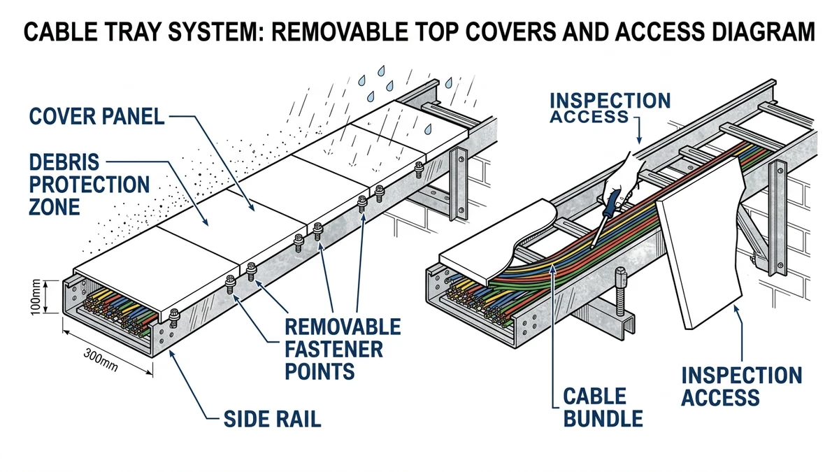
Cable tray covers are removable metal or nonmetal panels installed over a cable tray or cable ladder to reduce exposure to dust, falling debris, UV, and light weathering. Under IEC 61537, they change exposure, access, and thermal behavior; they do not turn an open tray into a sealed raceway. In practice, a 1.0 mm to 2.0 mm cover can improve physical protection, but it also adds weight, slows maintenance access, and may require ampacity review where thermal margin is tight.
The real decision is not whether covers are “better,” but whether the hazard reduction is worth the penalties in heat dissipation, inspection time, and support loading. That trade-off should be made route by route, not applied uniformly across a facility.
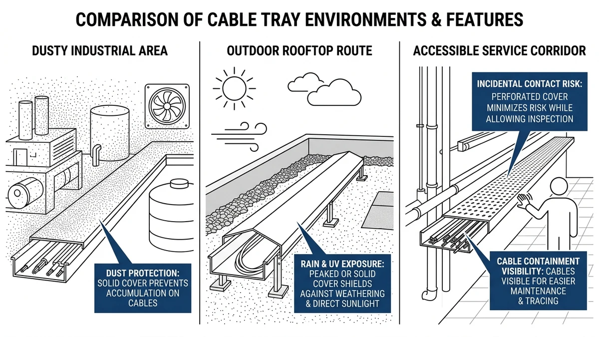
Cable tray covers mainly protect against falling debris, contamination, and weather-driven exposure from above. They help most when the threat is external and predictable, and less when the route needs frequent access or already runs close to thermal limits.
Where trays run below steelwork, grating, piping, or maintenance platforms, covers help prevent dropped bolts, concrete chips, or tool fragments from striking cable jackets. The main benefit is impact shielding, but it comes with added dead load and slower inspection.
In cement, textile, woodworking, and similar areas, covers reduce settled debris from overhead sources and keep cable tags and jackets cleaner between shutdowns. They do not fully stop fine particle ingress at joints, splice gaps, or fittings, so the gain is reduced contamination, not dust-tight performance.
Outdoor tray and ladder runs benefit from covers mainly against vertical rainfall, light splash, and dirt washed off nearby structures. A simple top cover is not a watertight or IP-rated enclosure, especially where wind-driven rain or hose-down cleaning at 3 bar to 5 bar is present. Ingress protection should be specified for the tested assembly, not assumed from the tray cover alone.
Covers reduce direct solar exposure on cable jackets and can limit casual contact or snagging during nearby work. But they can also reduce convective cooling and, if dark-colored, increase solar heat gain, so the protection benefit must be balanced against thermal effect.
Cable tray covers do not make tray systems equivalent to conduit, duct, or sealed trunking. Their actual performance depends on overlap, fastening, fitting continuity, and installation quality.
Cable tray covers improve protection, but they slow access. Every cover adds a removal and reinstallation step before technicians can inspect cable condition, verify fill ratio, identify circuits, or add new cables.
A useful planning assumption is that a visual check taking about 2 minutes on an open tray may take 10 minutes to 20 minutes at the same point once fixed covers, loose fasteners, working height, and reinstallation are included.
| Parameter | Covered tray | Uncovered tray | Design consequence |
|---|---|---|---|
| Routine visual inspection | Slower; cover must be removed or opened | Immediate line-of-sight access | Accept longer inspection effort only where contamination risk justifies it |
| Fault finding | Slower identification and thermal spotting | Faster tracing and condition check | Covered runs benefit from clearer cable labeling and planned access points every 6 m to 12 m |
| Cable additions and rerouting | More labor and repeated hardware handling | Faster moves, adds, and changes | Better suited to stable power routes than high-change instrumentation routes |
| Protection from dust/debris | Better | Limited | Lower cleaning frequency may offset access penalties in dirty environments |
| Weather and UV exposure | Better, depending on geometry and overlap | Poorer | Outdoor runs often justify covers if thermal review is acceptable |
| Risk of lost hardware | Present with loose fasteners | None | Hinged or quarter-turn designs reduce maintenance delays |
| Inspection quality | Hidden unless opened | Continuous visibility | Covered systems need deliberate opening strategy, not just cover supply |
If technicians expect to access a route more than once or twice per year, hinged covers or quick-release hardware usually save enough labor to justify the higher initial cost. If access is rare and contamination control is the priority, fixed overlap covers are often more practical.
[Expert Insight]
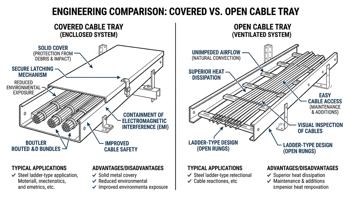
Yes. Cable tray covers reduce natural convection above the cable bundle, which can raise cable operating temperature and reduce usable ampacity. The effect depends on tray type, cable fill, load factor, cover geometry, ambient temperature, and solar exposure.
A solid top cover usually creates the largest thermal penalty because it restricts buoyant airflow directly above the cables. Internal air temperature can rise by several °C to more than 10 °C, especially on wider trays—around 450 mm to 900 mm—with closely grouped multicore power cables and high fill ratios.
If tested data for the covered arrangement is not available, treat the cover as a derating condition and verify the cable ampacity accordingly.
On outdoor runs, a cover can add solar heat gain as well as restrict convection. Under summer ambient conditions around 40 °C, that combined effect can be more significant than the cover alone, so covered outdoor tray runs generally need a more conservative review than indoor runs.
If a cover raises cable temperature, the normal response is redesign rather than assumption. Typical options are to reduce fill ratio, separate heavily loaded circuits, increase tray width, use ventilated covers, reduce solar gain, or increase conductor size where justified.
The key point is simple: a cable tray cover is a thermal design variable, not just a protection accessory.
Cable tray cover selection should be based on ingress exposure, access frequency, and thermal penalty. The best choice is usually the one that controls the dominant hazard with the least impact on maintenance and cable performance.
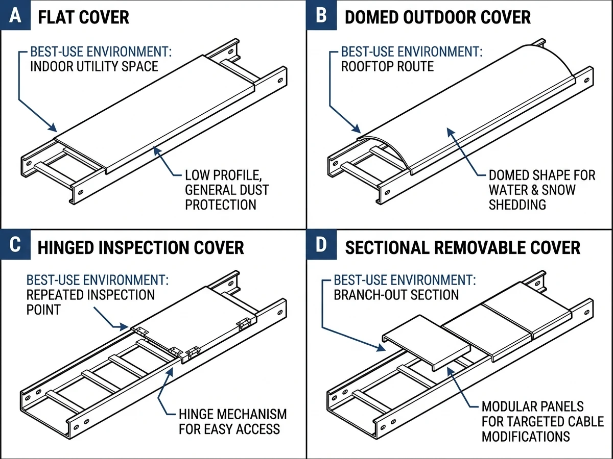
| Cover type | Best-fit environment | Main advantage | Main limitation | Typical design note |
|---|---|---|---|---|
| Flat solid cover | Indoor dry areas, plant rooms, light dust | Simple geometry, good falling-debris protection | Slower access; higher thermal penalty than ventilated options | Common on 100 mm to 600 mm tray widths; review derating if fill exceeds 40% |
| Domed or peaked cover | Outdoor exposed runs, rooftops | Better rain shedding and stiffness; less water pooling | Higher profile and more wind area | Review uplift and clamp spacing on supports around 1.5 m to 3.0 m |
| Hinged cover | High-maintenance control and instrumentation routes | Fast re-entry and inspection | More hardware; hinge durability matters outdoors | Useful where access is monthly or quarterly |
| Latching or clamp-down cover | Outdoor industrial zones, vibration areas | Better retention under vibration and wind | Slower to remove than hinged types | Better where mechanical security matters more than access speed |
| Ventilated or perforated cover | Warm indoor spaces needing partial shielding | Less thermal buildup than solid covers | Limited dust and weather protection | Suitable where heat dissipation is tight and shielding needs are moderate |
| Non-metallic cover | Corrosive or chemically aggressive areas | Corrosion resistance and electrical isolation | UV aging and lower impact strength unless rated | Confirm temperature class and outdoor suitability above 50 °C ambient if exposed |
A domed cover is better than a flat one only when runoff and stiffness matter enough to justify added wind area. A hinged cover is better only when repeated access saves enough labor to offset the higher cost and hardware complexity.
[Expert Insight]
Engineers should specify covered tray routes when external exposure controls the design. They should leave trays open when heat dissipation, rapid inspection, or regular cable changes matter more.
Specify covers where the system is exposed to falling debris, dust, dripping water, wind-blown contamination, or direct sunlight. If a tray is outdoors for more than 10 m to 20 m without shelter or another enclosure, the cover often becomes part of the environmental protection strategy, but dead load, uplift, fastening, and support reaction still need review.
Open tray is usually the better choice for power circuits running near ampacity limit and for control or instrumentation routes with regular adds, moves, and changes. If the design has less than about 10% thermal margin, adding covers late can force conductor upsizing or route changes.
Specify covered tray routes when:
Leave trays open when:
Selective coverage often works best: outdoor sections covered, indoor electrical rooms open, and high-change instrumentation runs left accessible.
Cable tray covers should be specified as part of the full cable management system. Once selected, they change dead load, support span, ampacity review, and fittings continuity.
A solid steel cover can add roughly 3 kg/m to 8 kg/m on a 300 mm to 600 mm tray. Over support spans of 2.5 m to 3.0 m, that added mass can materially change hanger loading and deflection checks, and on exposed routes wind uplift may become another design constraint.
More mass and more exposed surface area increase reactions at supports and restraints. In practice, long outdoor straight runs often use cover fixing intervals around 1.0 m to 1.5 m, with extra restraint where wind uplift or vibration is credible.
If support spacing is still under review, this coordination should happen before procurement. A late cover addition can invalidate earlier assumptions, which is why tray support layout directly affects load path, deflection, and maintenance access.
Specifications are often coherent on straight sections and inconsistent at fittings. If straights are covered but bends, reducers, tees, and risers are not detailed with matching covers and fastening method, the route loses protection continuity and becomes harder to maintain.
Before standardizing a cover type, verify compatibility with system fittings and connection details. The assembly has to work through direction changes, not just on catalog straight lengths.
Use when:
– the route is exposed and stable
– contamination reduction has measurable maintenance value
– support loads and cable temperature have been reviewed
– fittings can be covered consistently
Avoid when:
– the tray carries frequently modified controls or instrumentation
– the route already operates close to cable thermal limit
– access at height will make routine opening disproportionately costly
Check before specifying:
– tray width, fill ratio, and expected cable additions
– support spacing and revised load calculations
– fastening method under wind or vibration
– fitting-by-fitting continuity
– whether an open tray, ladder, or alternative distribution path would coordinate better with the electrical design
For broader system planning, this is usually the point where specifiers compare cable tray system options, review route sizing with a practical tray dimension guide, and decide whether some high-current runs are better served by busway distribution for concentrated loads. If the route remains tray-based and needs exposed-run protection, the final decision should align cover type with tray geometry—for example, on ladder tray configurations used on outdoor power runs—so support, fittings, and maintenance procedures all stay coordinated.
The technical reason to involve the manufacturer is system validation: confirming cover compatibility at bends and risers, checking added load and deflection, and reviewing whether the covered configuration still meets the intended operating and maintenance conditions.
Not typically. They can reduce direct rain and debris from above, but water can still enter through ends, joints, and fittings unless the full assembly is designed and tested for that exposure.
Choose a solid cover when debris or contamination control matters more than heat dissipation. Choose a ventilated cover when some shielding is useful but cable temperature margin is limited.
They often are on routes that need repeated inspection, troubleshooting, or cable changes. Where access is rare, fixed covers may be more economical.
Often yes. Covers add weight and can increase wind exposure, so support spacing, hanger load, and retention details may need to be recalculated.
Yes, selective coverage is often the most balanced approach. It can protect exposed outdoor or dirty sections while preserving open access in clean indoor areas.
Review cable temperature margin, support loading, fitting compatibility, and maintenance access first. Late changes can affect conductor sizing, support details, and installation labor.
