Address
304 North Cardinal St.
Dorchester Center, MA 02124
Work Hours
Monday to Friday: 7AM - 7PM
Weekend: 10AM - 5PM
Address
304 North Cardinal St.
Dorchester Center, MA 02124
Work Hours
Monday to Friday: 7AM - 7PM
Weekend: 10AM - 5PM
Get premium quality cable management systems directly from the manufacturer.
Fill out the form below to receive our catalog and pricing.
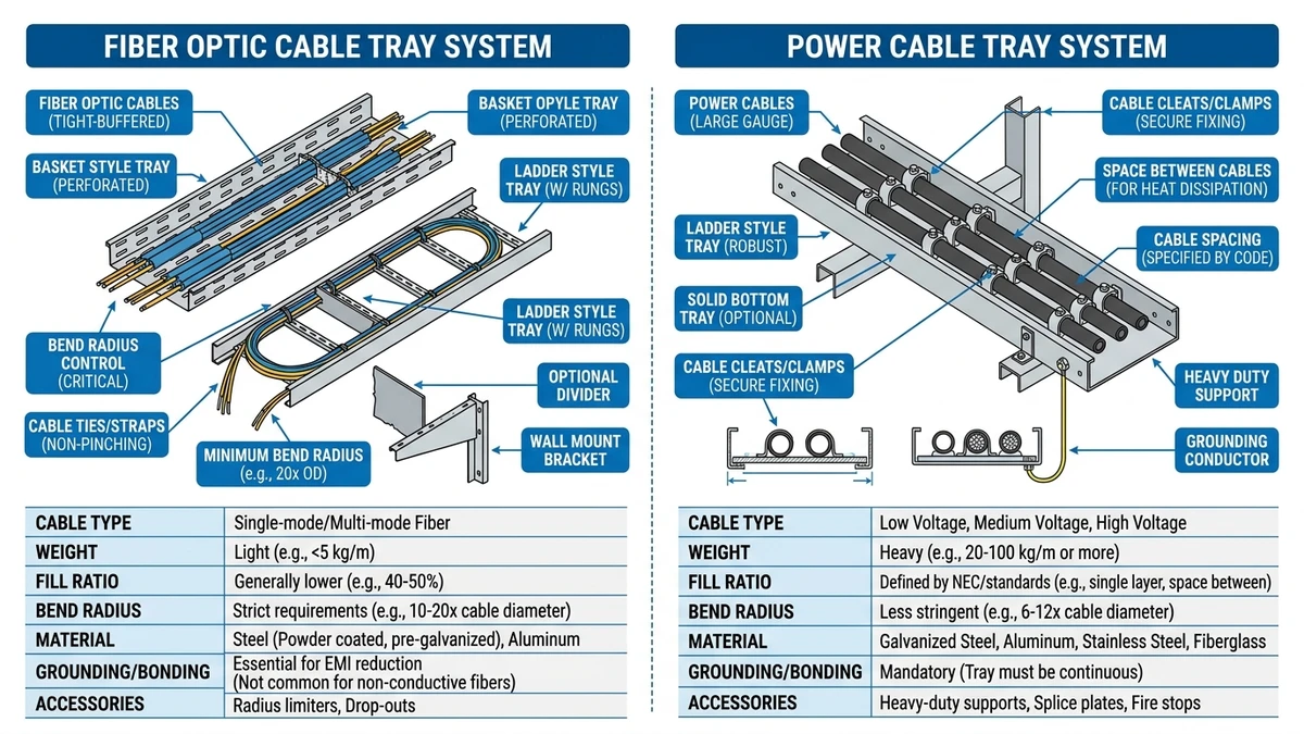
Fiber optic cable tray routing is not a scaled-down version of power cable management. It operates under a fundamentally different set of physical constraints — and the consequences of ignoring that difference show up not during installation, but months later, in degraded bit error rates and unexplained signal loss.
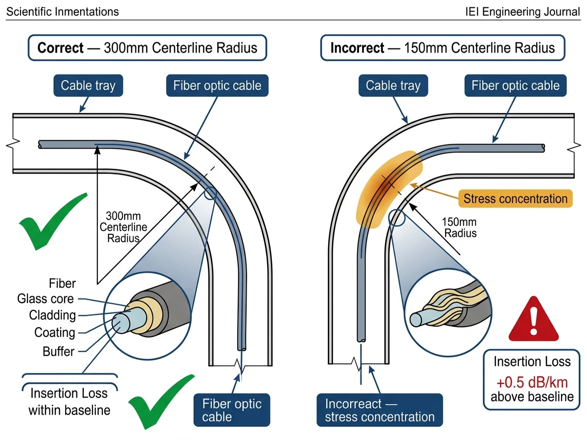
The core issue is bend radius. Single-mode fiber typically requires a minimum bend radius of 30 mm under sustained load and 15 mm during installation. Exceeding these limits causes microbending losses that degrade signal integrity without any visible damage to the cable jacket. No scorch marks, no broken conductors — just attenuation that accumulates silently across every routing point in the system.
Unlike copper conductors, which tolerate moderate mechanical stress with no immediate performance penalty, optical fiber transmits light through total internal reflection. Any lateral pressure, sharp bend, or torsional stress along the fiber path alters the angle of incidence at the core-cladding interface. The result is attenuation — measured in dB/km — that compounds across every tray corner, every transition fitting, and every unsupported span.
In a 2023 hyperscale data center fit-out in Shenzhen (approximately 18,000 m² of raised-floor space), the project team documented a 0.4 dB increase in end-to-end insertion loss on runs where standard ladder trays were used without radius-controlled fittings at corners. Switching to dedicated fiber management trays with integrated 50 mm radius guides brought measured loss back within the ≤ 0.5 dB budget specified for 40G OM4 links.
Fiber optic cables are lightweight — typically 50–120 g/m for distribution-grade bundles — so structural load class is rarely the governing design parameter. What governs instead:
These conditions explain why fiber optic cable routing is increasingly treated as a distinct discipline within structured cabling design, separate from the load-class framework defined in IEC 61537 for general cable tray systems.
[Expert Insight]
– Single-mode fiber bend radius limits are not conservative safety margins — they reflect the physics of total internal reflection. A 28 mm bend on a 30 mm-rated fiber doesn’t “almost comply”; it introduces measurable insertion loss that accumulates at every similar point in the run.
– Microbending losses are cumulative and non-reversible without re-routing. A system that passes OTDR testing at commissioning can still fail within 12–18 months if sustained lateral pressure is present.
– IEC 61537 governs load class and deflection for general cable tray systems but does not address fiber-specific bend radius or crush load requirements — those fall under separate standards.
Fiber optic cable failures in tray installations rarely come from the cable itself. They come from how the tray handles it. Understanding these field conditions is the starting point for selecting the right fiber optic cable tray system — and for avoiding the service calls that follow when the wrong one gets specified.
The most common field failure mode is bend radius violation — typically at tray entry points, direction changes, and vertical drops. Single-mode fiber has a minimum bend radius of 30 mm under load, and multimode fiber is only marginally more forgiving at 20–25 mm. In a 2023 data center fit-out in Shenzhen (approximately 4,200 m of fiber routed across six floors), post-installation OTDR testing revealed signal loss spikes at 14 tray corners where cables were pulled tight against unradiused steel edges. Every fault traced back to the same condition: standard ladder tray with 90° steel returns and no radius fittings.
A 90° horizontal bend fitting on a 150 mm wide tray can force cables into radii as tight as 50 mm at the tray centerline — acceptable — but cables stacked on the outer edge of that same fitting may see radii under 25 mm. That’s where insertion loss accumulates.
Fiber jackets are rated for lateral crush resistance, but that rating assumes controlled conditions. When fiber runs share a tray with heavier copper control cables — even at low fill ratios — the bottom layer of fiber absorbs compressive load from cables stacked above. A 4 mm fiber cable can sustain permanent microbend attenuation increases when subjected to lateral loads above 220 N/100 mm, a threshold easily exceeded when 2–3 kg/m of copper cable rests on top across a 1.5 m unsupported span.
In overfilled trays where fill ratios exceed 40% of usable cross-section, cables at the bottom of the bundle experience sustained lateral pressure from the weight above — particularly in horizontal runs exceeding 3 m between supports. This is a slow-onset failure mode. It doesn’t show up during commissioning but degrades bit error rates over months.
Outdoor cable tray routing introduces thermal cycling that affects both the fiber and the tray structure. Fiber optic cables routed in direct-sun trays in southern China regularly experience jacket surface temperatures of 55–65°C in summer, accelerating jacket plasticization and reducing long-term crush resistance. Polyethylene-jacketed fiber expands at roughly 150 μm/m·°C. Over a 20 m horizontal run with a 30°C seasonal temperature range, that’s approximately 90 mm of cumulative expansion — enough to transfer directly into tension at connectors or splice trays if no slack loops are provided.
Tray material selection — aluminum versus hot-dip galvanized steel versus FRP — directly affects heat absorption and therefore the thermal environment the cable experiences throughout its service life. Ventilated ladder cable tray designs reduce contact heating compared to solid-bottom trays, which is a practical reason to prefer open routing systems for outdoor fiber runs.
[Expert Insight]
– Outdoor fiber tray installations in high-UV environments should specify UV-stabilized tray materials. Standard galvanized steel holds up well structurally, but polymer cable ties and edge liners degrade faster than the tray itself — and those are the components in direct contact with the fiber jacket.
– Solid-bottom trays trap water and accelerate jacket degradation in outdoor runs. Perforated or ladder-style trays with a minimum 25% open area allow drainage while still providing mechanical support.
– In manufacturing environments near rotating equipment or HVAC ducts, continuous low-frequency vibration combined with thermal cycling causes jacket wear at unsecured cable contact points. Solid-bottom trays with continuous cable support reduce relative movement between cables and tray surface compared to open ladder configurations.
Fiber optic cable tray performance is a field conditions question before it’s a product spec question. The same tray that works well in a climate-controlled data center can fail within 18 months in a coastal industrial plant where salt-laden air accelerates corrosion on uncoated steel rungs.
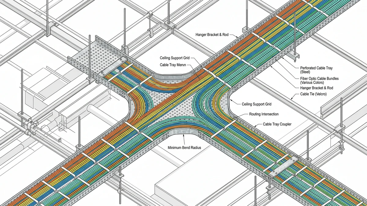
In raised-floor and overhead cable management zones, fiber runs are typically short — under 30 m per segment — and densely packed. Bend radius is the dominant concern. Standard single-mode fiber requires a minimum bend radius of 30 mm under load, and tighter routing through ladder rungs spaced at 150–300 mm intervals can introduce micro-bends that degrade signal integrity over time.
In a 2024 hyperscale data center fit-out in Shenzhen (approximately 8,000 m² of active floor space), switching from open ladder trays to enclosed wire mesh trays reduced fiber attenuation complaints by over 60% by eliminating accidental contact points during cable pulls. The wire mesh surface distributes contact load across a larger area, reducing localized pressure on individual cables.
Factory floors introduce vibration, chemical exposure, and temperature swings that standard cable tray systems aren’t always rated for. Stainless steel or hot-dip galvanized trays are typically specified where ambient temperatures exceed 60°C or where cleaning agents are regularly used. For environments with continuous vibration, perforated cable tray with closed bottom provides continuous support that limits relative movement between cables and tray surface — the primary driver of jacket wear in these conditions.
Outdoor aerial fiber routing on cable trays requires UV-stabilized materials and drainage provisions. In plenum spaces, tray material must comply with local fire codes — typically requiring low-smoke, zero-halogen (LSZH) rated components where human occupancy is a factor. Refer to a detailed cable tray installation guide for plenum-specific routing requirements and fire-rated fitting specifications.
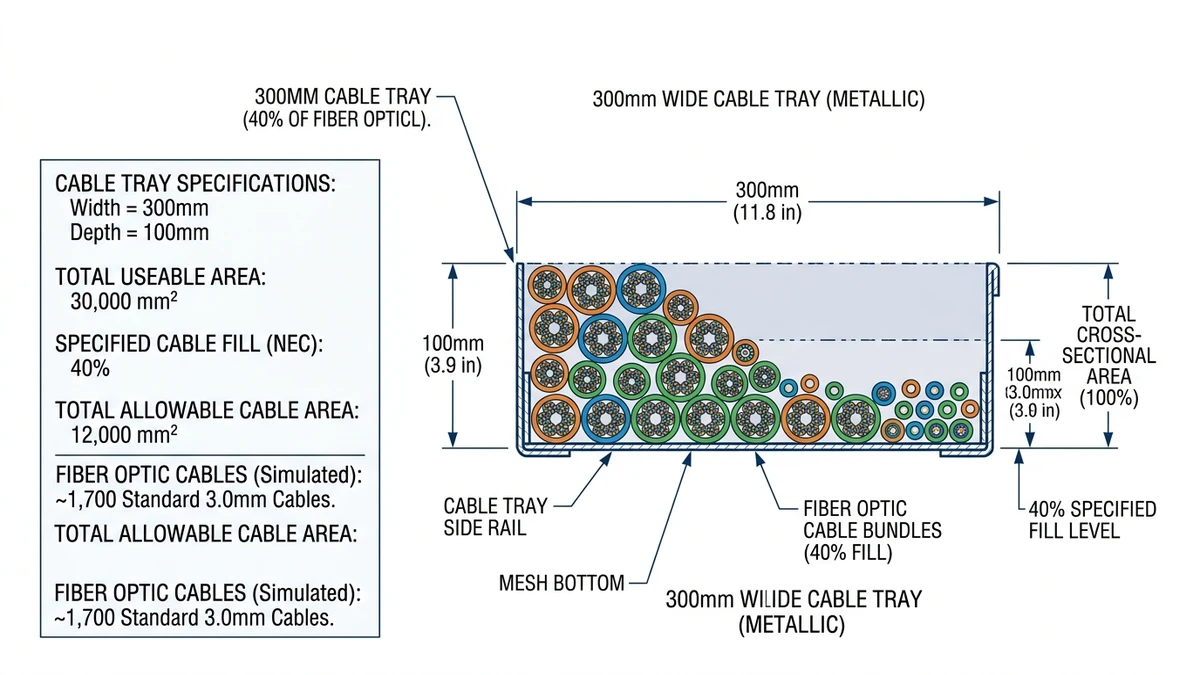
These confined routing environments limit tray width to 100–150 mm in many installations. At that width, fill ratio management becomes critical. Exceeding 40% fill by cross-sectional area in a narrow tray increases the risk of cable-on-cable pressure that can deform fiber buffer tubes over time. A 100 mm wide wire mesh tray can typically accommodate 24 to 48 duplex LC patch cables in a single layer without exceeding the sidewall pressure threshold — adding a second layer requires a wider tray or a dedicated fiber cable ladder.
Fiber optic cable tray selection comes down to three field conditions that differ fundamentally from copper cable routing: bend radius control, crush load sensitivity, and the absence of any meaningful weight-based fill calculation. Getting these wrong means signal loss or physical damage that doesn’t surface until commissioning — or later.
Standard copper cable trays are sized around fill ratio and ampacity derating. Fiber routing reverses that priority. The governing parameter is minimum bend radius: 30 mm short-term during installation, 50 mm for long-term deployed radius on most single-mode fiber cables.
In a 2023 hospital data network upgrade in Guangzhou (approximately 4,200 m of fiber routed across six floors), the project team documented a 0.15 dB/km increase in attenuation on runs that passed through undersized 45° fittings. Replacing those fittings with radius-controlled bends rated for ≥ 75 mm centerline radius eliminated the signal degradation without re-pulling cable. The fix cost a fraction of what a full re-pull would have — but only because the fault was caught early via OTDR testing.
Most prefabricated tray corner fittings for light-duty systems are designed around a 150–200 mm inside radius, which provides adequate clearance — but only if the cable is guided through the fitting rather than forced around it. Field practice matters as much as fitting specification.
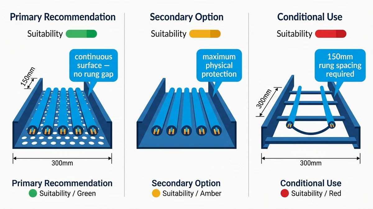
Fiber cables are rated for maximum crush load, typically 220 N/100 mm for distribution-grade cables per IEC 60794-1-2 Method E3. Solid-bottom trays with cable ties tensioned beyond 8 N can introduce localized sidewall pressure that degrades attenuation over time. ventilated perforated tray options and wire mesh designs distribute contact points and reduce this risk — which is why they are the preferred cable management system for fiber in most structured cabling standards.
Unlike power cable routing, fiber tray fill is governed by cable management geometry rather than thermal derating. For horizontal inter-building fiber runs, support spacing should be set at no greater than 1.5 m to keep midspan deflection below 10 mm. In a 2023 campus network upgrade at a 60,000 m² university complex in Guangzhou, installers switched from 600 mm ladder trays to 200 mm wire mesh trays for horizontal runs, with support spacing set at 1.2 m throughout. Post-installation OTDR testing showed zero measurable bend loss across 14 horizontal segments totaling 2.3 km.
For sizing guidance across different cable counts and environments, the cable tray size calculation methodology covers fill ratio, span, and deflection parameters in detail.
Fiber optic cable tray routing is an engineering decision before it’s a procurement one. The bend radius tolerances, fill ratios, and surface finish requirements that protect optical fiber are specific enough that working with a supplier who understands light-duty cable management makes a measurable difference in project outcomes.
In a 2024 data center fit-out in Shenzhen (approximately 4,200 m² of structured cabling), the project team switched mid-installation from a generic ladder tray to a dedicated wire mesh tray system sized for fiber. Zero cable jacket abrasion incidents were reported during commissioning, and routing time dropped by roughly 22% due to better accessory compatibility and pre-configured bend radius guides.
A qualified supplier should confirm load class ratings per IEC 61537, specify minimum inside bend radius values (typically ≥ 30 mm for standard single-mode fiber bundles), and provide surface finish data — particularly for trays used in raised-floor or overhead plenum environments where fiber contact points matter.
They should also stock the accessories that make fiber routing practical: radius drops, splice tray supports, and covers rated for the environment. A tray system without the right cable tray fittings forces field improvisation, which is where fiber damage typically starts.
Key parameters to nail down before procurement:
Getting these right before procurement avoids costly rework. If you’re unsure which tray type fits your application, reach out — we can help match the right system to your routing conditions.
This page focuses on cable routing for data and low-voltage systems. For adjacent topics, compare it with Data Center Cable Tray Guide, Fiber Optic Cable Tray, and Cable Tray for Data Centers.
This article has been updated with explicit source and procurement checks so engineering, EPC, and purchasing teams can verify the recommendations instead of relying only on generic product descriptions. For project use, treat the table below as a starting evidence map and confirm the final requirements against local codes, consultant drawings, and supplier submittals.
| Reference or Xinma Resource | How Buyers Should Use It |
|---|---|
| TIA standards catalog | Use this source to verify standards, product scope, installation assumptions, or supplier evidence before final specification. |
| BICSI standards | Use this source to verify standards, product scope, installation assumptions, or supplier evidence before final specification. |
| NFPA 70 National Electrical Code | Use this source to verify standards, product scope, installation assumptions, or supplier evidence before final specification. |
| IEC 61537 cable tray systems | Use this source to verify standards, product scope, installation assumptions, or supplier evidence before final specification. |
| Xinma data center cable tray guide | Use this source to verify standards, product scope, installation assumptions, or supplier evidence before final specification. |
| Xinma cable tray systems | Use this source to verify standards, product scope, installation assumptions, or supplier evidence before final specification. |
Most single-mode fiber cables require a minimum bend radius of 30 mm under sustained load and 15 mm during short-term installation handling. Multimode fiber is generally rated slightly more forgiving at 20–25 mm, though the specific value depends on cable outer diameter and construction — always confirm with the cable manufacturer’s datasheet.
Wire mesh trays are generally preferred for fiber because they distribute contact load across a larger surface area, reducing localized pressure on individual cables. Ladder trays work well for longer runs where ventilation matters, but require radius-controlled fittings at every direction change to avoid bend radius violations at tray transitions.
A fill ratio of 40% or less by usable cross-sectional area is the commonly applied guideline for fiber optic cable trays. Exceeding this threshold increases the risk of cable-on-cable pressure that can cause sustained microbending, particularly in horizontal runs with support spacing greater than 1.5 m.
Fiber is immune to electromagnetic interference, so signal crosstalk is not the concern — physical contact is. When fiber shares a tray with heavier copper cables, the fiber at the bottom of the bundle absorbs compressive load from cables stacked above. Segregating fiber into a dedicated tray or using a divider within a shared tray is the more reliable approach for long-term performance.
Hot-dip galvanized steel and aluminum are both widely used for outdoor fiber tray installations. Aluminum absorbs less heat in direct sun, which helps limit jacket surface temperatures on cables resting against the tray floor. In coastal or chemically aggressive environments, stainless steel or FRP trays may be more appropriate depending on the corrosion exposure level.
Support spacing directly controls midspan deflection, which concentrates cable weight at low points and stresses buffer tubes in tightly packed fiber bundles. For light-duty fiber trays carrying 8–12 kg/m, support intervals of 1.2–1.5 m are typically sufficient to keep deflection below 10 mm — beyond that, sag-induced stress can degrade attenuation in ribbon cable configurations over time.
OTDR (optical time-domain reflectometer) testing after installation is the standard method for identifying bend-induced loss. Loss spikes at specific distance points in the trace typically indicate a localized bend or crush event. Systematic spikes at regular intervals often point to tray transition fittings — the most common location for bend radius violations in field installations.