Cable tray dimensions determine whether your cable management system performs safely for decades or becomes a costly retrofit. Before placing any order in 2026, buyers must confirm five specific dimensional parameters — not just the nominal width listed in a catalog. In a pharmaceutical plant expansion project in Suzhou (2023), mismatched tray depth specifications caused a 14-day installation delay and ¥180,000 in rework costs when purchased trays couldn’t accommodate the actual cable bundle diameter. That single procurement shortcut cost more than the trays themselves.
Understanding what those parameters are — and where the gaps between catalog numbers and real-world performance hide — is the entire purpose of this guide.
Types of Cable Tray: Matching the Form to the Application
Before checking any dimension on a cable tray spec sheet, confirm you are looking at the right tray type. Selecting a ladder tray where a solid-bottom wire tray is required — or vice versa — creates fill ratio problems, ventilation failures, and rework costs that no dimensional accuracy can fix.
Ladder trays consist of two longitudinal side rails connected by transverse rungs, typically spaced 150 mm to 300 mm apart. This open structure allows free airflow around cables, making ladder trays the standard choice for power cables where heat dissipation directly affects ampacity derating. In a 2024 petrochemical plant expansion in Zhoushan, China, switching from solid-bottom to ladder trays on 240 mm² MV feeder runs reduced required derating factors from 0.72 to 0.91, recovering nearly 19 kW of usable capacity across 14 parallel circuits — without upsizing conductors.
Ladder trays are governed by IEC 61537, which classifies load capacity from Class A (50 kg/m) through Class D (200 kg/m) and sets maximum midspan deflection at L/200 under proof load.
Solid-Bottom and Perforated Cable Tray
Solid-bottom trays provide continuous support across the tray floor — critical for instrumentation cables, fiber optic bundles, and small-diameter control wiring where rung spacing would leave cables unsupported or subject to mechanical stress. Perforated trays offer a middle ground: partial ventilation with more uniform cable support than ladder rungs. For instrumentation and data cable routing, NEMA VE 1 defines minimum metal thickness and perforation patterns that affect both load capacity and electromagnetic shielding behavior.
Wire Mesh Cable Tray
Wire mesh cable tray — also called wire basket tray — has expanded significantly in data center and building management cable routing since 2022. Its three-dimensional grid structure allows cables to exit at any point without knockout punches, reducing installation time. Typical wire diameter runs 4 mm to 6 mm, and mesh trays generally carry lighter load classes. Buyers specifying mesh for loads above 30 kg/m should verify manufacturer load test data against the intended span.
Choosing the wrong tray type before checking width, depth, or span is the most common procurement error buyers make. Lock in the type first; then every dimensional parameter in the sections below applies correctly.
[Expert Insight]
Ladder tray airflow advantage disappears when cables are stacked above the side rail height — a condition that occurs more often than buyers expect on high-density motor feeder runs.
Wire mesh trays require galvanic compatibility checks with cable armor materials; zinc-coated mesh in contact with aluminum-armored cables in high-humidity environments can accelerate corrosion at contact points.
Perforated solid-bottom trays are often the overlooked compromise for mixed power-and-instrumentation routing, providing mechanical support without eliminating ventilation entirely.
Always confirm the tray type is explicitly named in the specification — not inferred from a photo in a catalog.
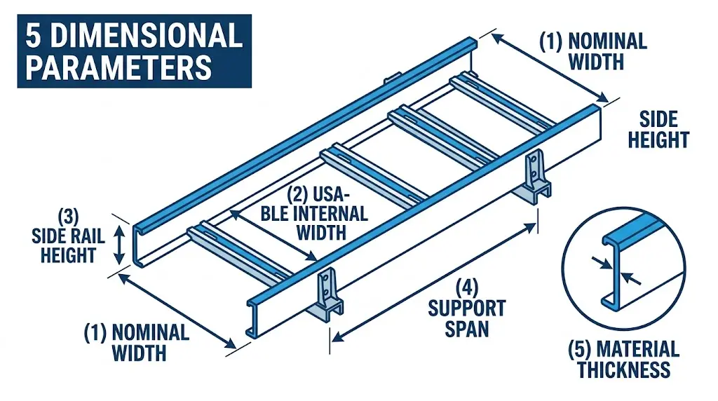
Nominal Width vs. Usable Width: The Gap Buyers Miss
Manufacturers list cable trays by nominal width — typically 100 mm, 150 mm, 200 mm, 300 mm, 400 mm, 500 mm, or 600 mm — but this figure describes only the outer-to-outer measurement of the side rails. Usable internal cable fill width is consistently narrower. Confusing the two is one of the most common sizing errors in procurement, and it compounds across every fill ratio calculation downstream.
How Much Width Is Lost?
For a ladder cable tray with pressed steel side rails, the rail wall thickness typically consumes 2–4 mm per side. That sounds minor. But a nominal 300 mm tray often delivers only 290–292 mm of internal routing space, and at 600 mm nominal width, internal fill width is typically 588–592 mm. The gap widens further once you account for integral cable tie anchor points or lip returns on the rail edge. External width runs 20–40 mm wider than nominal — meaning a tray specified at 300 mm nominal typically measures 330–340 mm externally, which matters when multiple trays share a common rack or threaded-rod hanger.
In a 2024 industrial cable routing project at a 120,000 m² automotive assembly plant in Changzhou, procurement specified 400 mm nominal ladder trays based on cable bundle diameter calculations alone. Post-installation audit revealed 17% of tray runs exceeded the 40% fill ratio threshold defined in IEC 61537 — because the fill calculations had used nominal rather than internal width. Remediation required upsize replacement on 230 linear meters of tray.
The IEC 61537 Fill Ratio Reference
IEC 61537 (Cable Management — Cable Tray Systems and Cable Ladder Systems) governs both load classification and cable fill methodology. It treats internal cross-sectional area — not nominal width — as the basis for fill ratio calculations. A commonly applied design ceiling is 40% fill of internal usable area, leaving margin for heat dissipation and future cable additions. Exceeding 50% fill in a mixed power-and-signal tray is a thermal and maintenance risk, not just a standards deviation.
Figure 1. Cable tray rail cross-section illustrating the dimensional gap between nominal width (outer-to-outer) and usable internal width (inner-to-inner), determined by wall thickness and return flange geometry — a critical variable in cable fill ratio calculations.
The Four Dimensions to Request From Any Supplier
When evaluating a cable tray system, request the full dimensional data sheet and confirm these four values as separate specification lines — not derived from nominal:
Internal usable width (W) — the net space for cables, not the rail-to-rail center measurement
Side rail height (H) — standard ladder trays range from 50 mm to 150 mm; deeper rails support higher load classes
Steel thickness — perforated and solid-bottom trays are commonly available in 1.2 mm, 1.5 mm, and 2.0 mm; thicker stock increases Class C or Class D load ratings under IEC 61537
Span-to-deflection ratio — at a 3 m support span, a properly rated Class C tray must not deflect more than L/200 (15 mm) under rated load
Legrand, OBO Bettermann, and Niedax all publish CAD libraries where dimensional tolerances are explicitly stated. Cross-reference these against your project’s bill of materials before approval.
Depth-to-Width Ratio: Why Tray Geometry Affects Cable Fill and Heat Dissipation
Width alone doesn’t size a tray. The ratio of usable depth to internal width directly controls how cables stack, how heat escapes, and whether your installation meets fill-ratio limits under IEC 61537. Buyers who specify width and ignore depth consistently underperform on ampacity derating calculations — and typically discover this only after the tray is already installed.
How Depth Governs Cable Fill Capacity
Standard cable tray depths range from 50 mm (shallow channel trays) to 150 mm (deep ladder or solid-bottom trays), with 100 mm being the most common general-purpose depth in commercial and industrial installations. Usable cross-sectional area for cable fill is internal width × internal depth — but that number means nothing without knowing your required fill ratio.
IEC 61537 recommends a cable fill ratio not exceeding 40% of the internal tray cross-section for multiconductor power cables operating at full rated current. In a 300 mm wide × 100 mm deep ladder tray, the gross cross-section is 30,000 mm². At 40% fill, you have 12,000 mm² available for cables — a figure that must be checked against the summed cross-sections of every cable routed through that segment.
In a 2023 petrochemical plant expansion in Ningbo (24 cable tray runs, 480 m total), engineers initially specified 300 mm × 75 mm trays to save material cost. Thermal modeling showed power cable bundles exceeded the 40% fill limit by 18%, requiring a retrofit to 300 mm × 100 mm trays across 60% of the routing length — adding approximately ¥85,000 in rework costs.
Depth Interaction With Ampacity Derating
Deeper trays allow cables to spread laterally across rungs, reducing bundling effects. Shallow trays force vertical stacking, which increases the derating factor applied to cable ampacity. typically requires derating to 70–85% of rated ampacity when three or more cable layers are stacked in a tray with depth below 75 mm. For solid-bottom trays used in data centers, a minimum 100 mm internal depth is generally advisable to maintain adequate airflow beneath cable bundles.
When reviewing procurement documents, confirm that internal depth — not external — is stated, since flanges and side-rail thickness typically consume 6–10 mm per side. Also verify that the supplier’s published cross-section accounts for rung thickness in ladder trays, which reduces effective fill depth by 8–12 mm at rung locations.
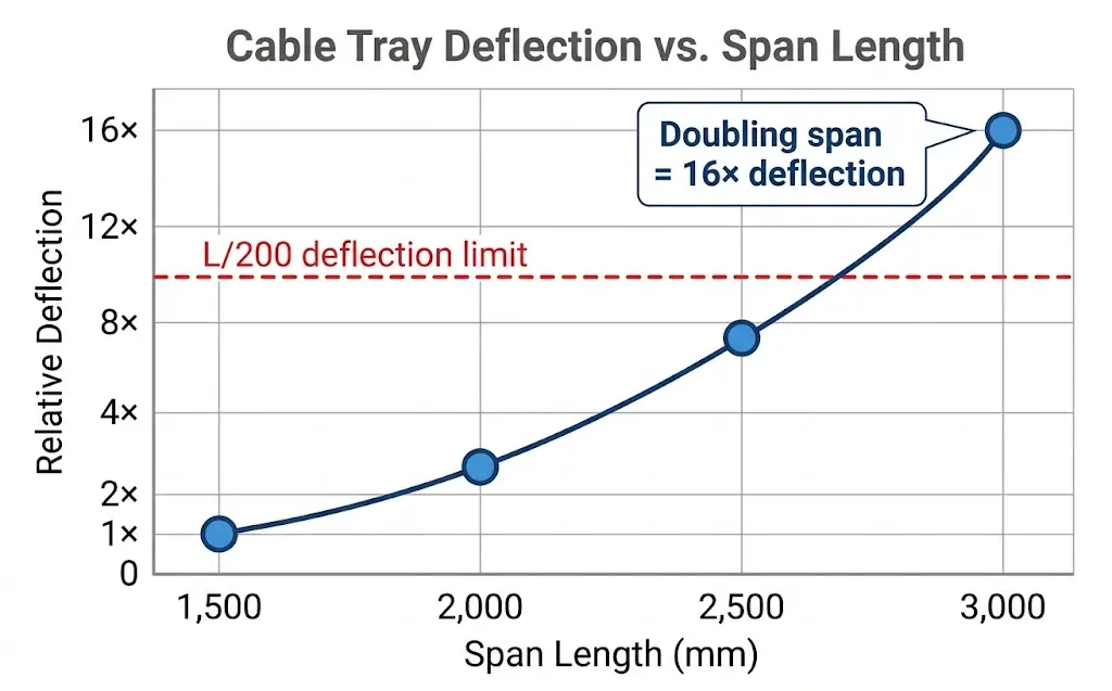
Figure 2. Relative deflection versus span length for a cable tray under constant distributed load, demonstrating the fourth-power (L⁴) relationship. At 3,000 mm span, deflection reaches 16× the value recorded at 1,500 mm — the primary reason manufacturers publish load ratings per span increment rather than a single value.
[Expert Insight]
The derating penalty for vertical cable stacking in shallow trays compounds with ambient temperature — a 75 mm deep tray in a 45°C plant environment may require derating to 65% of rated ampacity on the bottom cable layer.
Specifying 100 mm depth as a project standard — even where 75 mm would technically pass — costs roughly 8–12% more in material but eliminates the most common derating recalculation requests during commissioning.
Rung thickness is almost never called out in catalog summaries; it must be read from the fabrication drawing, and it can consume up to 12 mm of nominal depth at each rung crossing.
Mounting and Support Spacing: The Dimension Most Buyers Overlook
Support spacing is one of the most consequential dimensions a buyer can specify — yet it rarely appears on purchase orders. The distance between hangers or brackets directly controls midspan deflection, load capacity, and long-term structural integrity across the entire cable management system.
How Support Spacing Affects Load Rating
Cable tray load ratings published by manufacturers are always tied to a specific span length. A ladder cable tray rated at 150 kg/m at a 1,500 mm support interval carries significantly less load if installers space supports at 2,400 mm. In the same pharmaceutical plant expansion in Suzhou mentioned earlier, field engineers discovered that substituting 2,000 mm spans for the specified 1,200 mm spans reduced effective load capacity by approximately 38%, causing visible deflection under a 90 kg/m cable fill — a direct result of misreading the manufacturer’s span-load table rather than the tray width specification.
IEC 61537 requires manufacturers to declare load class performance at a defined reference span, typically 3,000 mm for ladder systems. Buyers must verify that the declared load class — Class A at 50 kg/m through Class D at 200 kg/m — matches the actual installation span in their project drawings.
Key Mounting Dimensions to Confirm Before Purchase
Three parameters must appear explicitly in your specification:
Maximum support span: Typically 1,500 mm to 3,000 mm depending on tray material, width, and load class. Do not assume the catalog rating applies at any span.
Hanger rod diameter and thread engagement: Minimum M8 (8 mm diameter) rods are standard for medium-duty applications; heavy-duty trays in seismic zones often require M12 (12 mm) rods with lock nuts per 。
Bracket setback from tray end: Most ladder tray specifications require a support bracket within 300 mm of each tray joint to prevent end-loading deflection at splice plates.
Material Influence on Span Behavior
Hot-dip galvanized steel cable ladders generally allow longer support spans than aluminum equivalents at equivalent load. Steel’s modulus of elasticity (~200 GPa) resists midspan deflection more effectively than aluminum alloy (~69 GPa). For wire tray and cable basket systems, maximum unsupported spans are typically shorter — often capped at 1,200 mm under standard fill conditions.
Confirming support spacing on the dimensional checklist is what separates a structurally compliant installation from one that deflects, strains, or fails during cable pulling.
Dimensional Tolerances and Fitment Checks Buyers Overlook
The stated width, depth, and length on a datasheet describe the nominal envelope. Fitment in real installations depends on manufacturing tolerances, connector compatibility, and how individual tray sections land on support steelwork. Skipping these checks is the most common reason trays arrive on site and don’t assemble cleanly.
Length Tolerances and Joint Alignment
Standard tray sections are manufactured in 2 m, 3 m, and 6 m lengths, but IEC 61537 permits a length tolerance of ±5 mm per section . Over a 30 m cable routing run using 3 m sections, that tolerance compounds to ±50 mm worst-case. In a 42-floor commercial tower in Guangzhou completed in 2024, unadjusted length tolerance caused coupler bolt holes to miss alignment by 12–18 mm at every third joint, requiring field drilling that added two days to the installation schedule.
On-Site Incoming Inspection
In a 2024 petrochemical plant expansion in Shandong Province (12,000 meters of cable tray installed), the procurement team identified dimensional non-conformances in approximately 4% of delivered tray sections during incoming inspection — primarily undersized rail heights at 54 mm instead of the specified 60 mm. This triggered a load recalculation delay of 11 days. The lesson is direct: measure at least 5% of received sections with a calibrated digital caliper before installation begins.
Certification bodies including UL, CSA, and KEMA issue load-class test reports that list the tested tray’s exact cross-sectional dimensions. A UL test report for a Class 20B tray (load capacity of approximately 88 kg/m at 3 m span) will specify rail height, rail gauge, and rung configuration used during testing. If the tray received deviates from those dimensions by more than the stated manufacturing tolerance — typically ±1.5 mm on rail height for steel trays — the certified load rating may no longer apply.
Always request the manufacturer’s issued-for-construction (IFC) dimensional drawing in DWG or PDF format, not just a marketing datasheet. Before ordering, that drawing should explicitly show both internal usable width and external overall width as separate values. For projects subject to incoming inspection requirements, cross-check supplier dimensions against your fill ratio design target before the purchase order is issued — not after delivery.
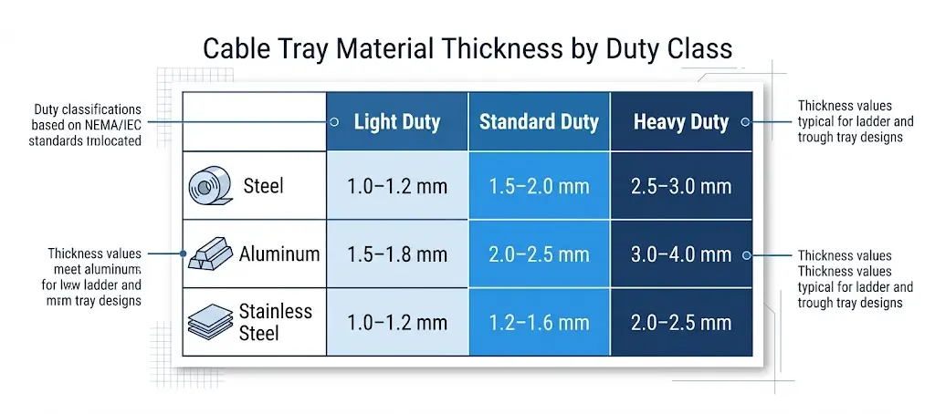
Figure 3. Cable tray material thickness ranges by duty class and material type. Base metal thickness directly determines load class rating and corrosion allowance — values shown are for structural base material before surface treatment.
Summary Checklist: Cable Tray Dimension Verification Before Purchase
Before issuing any purchase order, run a parameter-by-parameter check against installation requirements. In a 2024 petrochemical plant expansion in Shandong Province covering 14 cable routing zones across three process units, the procurement team caught three critical dimension mismatches during pre-order verification, avoiding roughly ¥280,000 in rework costs and a six-week schedule delay. These six checkpoints are what they used.
Tray Geometry
Confirm the internal usable width — not nominal. A tray listed as 400 mm wide may have an internal dimension of 370–385 mm after side rail thickness is accounted for. Verify tray depth matches cable bundle diameter, typically requiring at least 25 mm clearance above the top cable layer. Check the span length against the load class: IEC 61537 Class C trays at 600 mm width are typically rated for 3 m spans under 100 kg/m distributed load; exceeding either parameter requires a re-rating calculation.
Fill Ratio and Cable Count
Calculate fill ratio before ordering. A working rule is 40% fill for mixed power-and-signal trays, leaving adequate spacing for heat dissipation and future cable additions. If the calculated fill exceeds 50%, step up to the next width increment — typically in 100 mm increments from 200 mm to 900 mm.
Material and Finish Specification
Confirm coating type matches the corrosion zone. Hot-dip galvanized coating should meet a minimum 85 µm average zinc coating for outdoor and industrial environments. Stainless steel Grade 316 is required for coastal or chemical exposure zones; powder coat is acceptable for light indoor use only.
Dimensional Tolerance Documentation
Request mill certificates or test reports confirming side rail height and wall thickness tolerances. Rail height variance beyond ±2 mm across a long run affects splice plate alignment and increases installation labor.
Pre-Order Verification Checklist
Internal usable width confirmed (not nominal)
Tray depth ≥ cable bundle OD + 25 mm clearance
Span and load class cross-checked against IEC 61537 load table
Fill ratio calculated and within 40% target
Coating specification matched to corrosion category
Wall thickness and rail height tolerances documented
Load Class and Support Spacing
Cross-check the tray’s rated load class against your calculated cable fill weight and support spacing. A 600 mm wide ladder tray spanning 3 m under a 120 kg/m load requires at minimum Class C certification. For orders exceeding 500 m of cable management system, request pre-production samples and verify internal width, rung spacing, and coating thickness in-house or through a certified inspection body before the full batch ships.
Acting on these checkpoints before approval — not after installation — is the difference between a cable routing system that performs over a 25-year service life and one that triggers an audit in year two. If you need help mapping these parameters to a specific project specification, connect with a qualified cable tray supplier who can provide IEC 61537 certified documentation upfront.
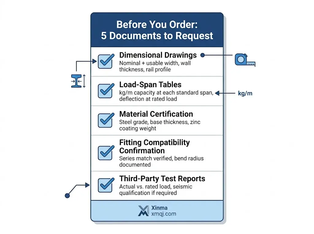
Figure 4. Pre-order document checklist for cable tray procurement. Each document category addresses a specific dimensional or performance risk — absence of any one item indicates an incomplete supplier submission.
Frequently Asked Questions
What is the difference between nominal width and usable width in a cable tray?
Nominal width describes the outer-to-outer rail measurement used in catalog listings, while usable width is the internal cable fill space after subtracting rail wall thickness — typically 2–4 mm per side — and any lip or anchor features. Always request internal usable width as a separate specification line before calculating fill ratios.
How do I calculate whether my cables will fit inside a cable tray?
Multiply the internal usable width by the internal depth to get the gross cross-sectional area, then apply a maximum fill ratio of around 40% for mixed power-and-signal runs; compare that available area against the summed outer diameter cross-sections of all cables routed through that segment.
What IEC standard governs cable tray load ratings and fill ratios?
IEC 61537 (Cable Management — Cable Tray Systems and Cable Ladder Systems) is the primary standard, covering load classes from Class A (50 kg/m) through Class D (200 kg/m), midspan deflection limits, and fill ratio methodology based on internal cross-sectional area.
How does support spacing affect a cable tray’s rated load capacity?
Manufacturer load ratings are always declared at a specific reference span — typically 3,000 mm for ladder systems under IEC 61537 — so increasing the span beyond that reference reduces the effective load capacity, sometimes by 30–40% at spans 60–70% longer than the rated interval.
When should I choose ladder tray over solid-bottom tray for power cables?
Ladder tray is generally preferable for power cables where ampacity derating is a concern, since the open rung structure promotes airflow and can significantly reduce the derating factor compared to solid-bottom trays — particularly for larger conductor sizes above 95 mm².
What coating specification should I require for outdoor or industrial cable tray installations?
Hot-dip galvanized coating with a minimum average zinc thickness of 85 µm is a widely used benchmark for outdoor and high-humidity environments, while stainless steel Grade 316 is the appropriate selection for coastal zones or areas with chemical exposure.
How many tray sections should I inspect on delivery before allowing installation to proceed?
Measuring at least 5% of received sections with a calibrated digital caliper — checking rail height, internal width, and wall thickness against the IFC drawing — is a practical incoming inspection threshold that has identified non-conformances before they affect installation schedule on large industrial projects.
Specification Evidence Table
Decision Point
What to Verify
Recommended Evidence
Load and support span
Confirm the tray width, support spacing, and allowable deflection for the installed route.
Load table, drawing revision, and IEC 61537 or equivalent test reference.
Material and finish
Match galvanized steel, stainless steel, aluminum, or FRP to the actual corrosion and installation environment.
Material certificate, coating record, and project corrosion category.
Accessory list, bill of materials, and installation drawings.
Installation and code fit
Confirm grounding, bonding, cable fill, separation, and access requirements.
NFPA 70 / NEC, consultant drawings, and local electrical code.
Related video: Cable Tray Width and Depth: How to Size It Right Before the Specification Is Frozen
Dimensions article: connect back to the sizing hub
This page covers the dimensions buyers need to verify. Use the sizing hub for the calculation workflow, then use these dimension and width pages as supporting checks.
Use this article as the focused specification reference for its topic, then cross-check product selection against Cable Tray Systems, Ladder Cable Tray Systems, and Perforated Cable Tray Systems. This prevents overlap between general education pages and product-specific procurement pages.
Kevin Zheng
Kevin Zheng is a manager linked to Shanghai Xinma Busway & Cable Tray Co., Ltd. He writes technical content on cable tray systems, installation practice, sizing logic, load classes, and related standards for industrial and infrastructure applications.