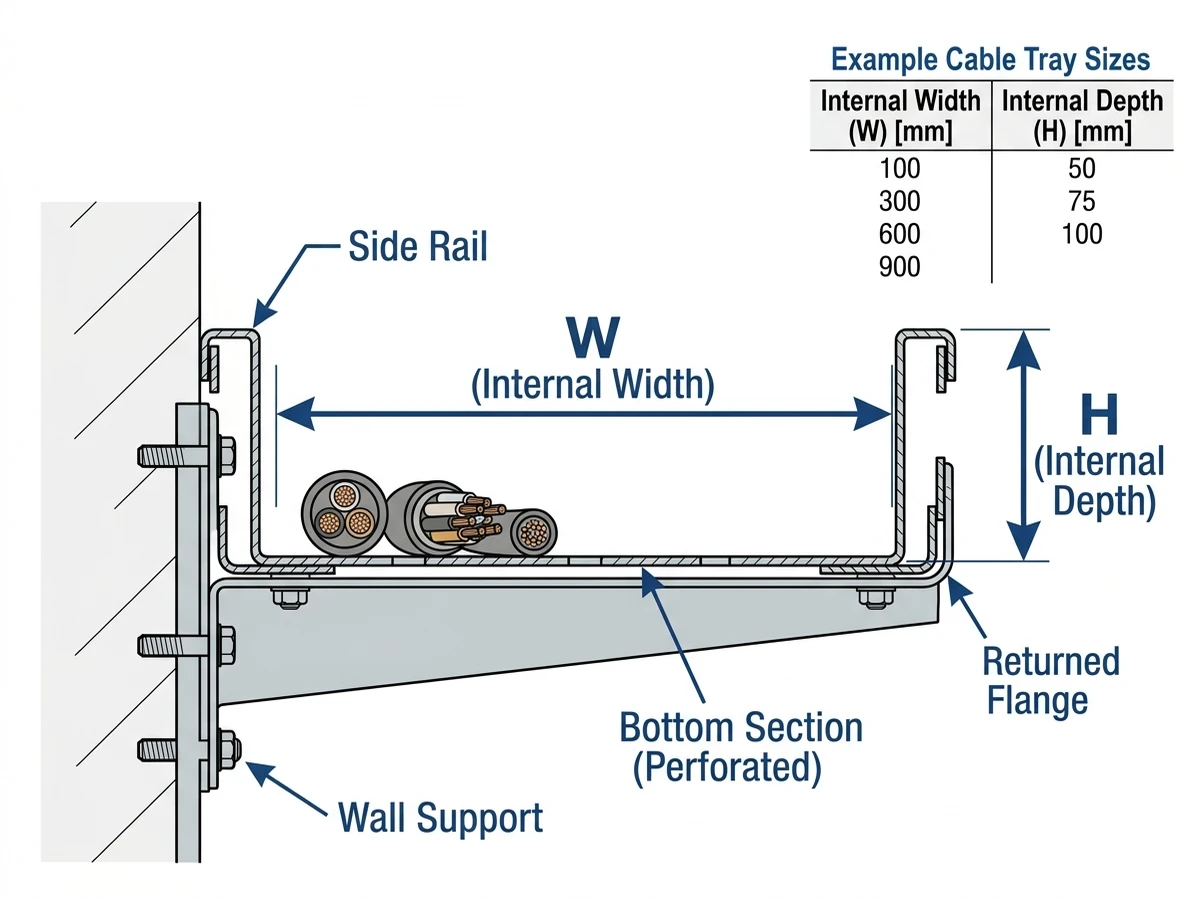
Standard Cable Tray Width and Depth: Core Definition and Ranges
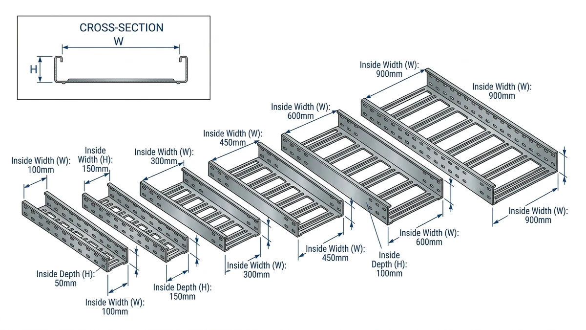
Standard cable tray width and depth are the nominal cross‑section sizes used to match tray capacity to cable quantity, routing space, and structural limits. In industrial systems, ladder or perforated tray widths typically range from 100–900 mm, with standard depths from 50–150 mm depending on load class and cable type.
In practice, 200 mm, 300 mm, 450 mm, and 600 mm widths are used most often. These are usually paired with 50–75 mm depths for control and LV power, and 100–150 mm depths for multi‑layer power cables or higher mechanical protection, following IEC 61537 and NEMA VE 1 catalogue dimensions for predictable fill and support span calculations.
If width is undersized (for example 200 mm instead of 300 mm), cables must be layered more deeply, increasing ampacity derating and making maintenance access harder. Oversized depth (e.g., 150 mm where 50 mm is enough) adds steel weight, may require shorter support spans, and complicates coordination with other services, so engineers typically size from total cable area and future growth, then step up to the next standard width and a minimum depth that meets stack height, stiffness, and span limits.
[Expert Insight]
– In multi‑year industrial expansions, one width step higher (e.g., 300 mm instead of 200 mm) often avoids adding a second tray later, which usually costs more in supports and downtime than the initial steel saving.
– On brownfield upgrades, shallow trays (≤50 mm) over main corridors are often overfilled; specifying ≥75 mm depth there can reduce ad‑hoc tie‑offs and non‑compliant add‑ons.
How Width and Depth Affect Load, Fill, and Structural Performance
Cable tray width and depth control how many cables can be carried, how heavy the system becomes per meter, and how the tray deflects under load, which sets limits on fill ratio, support spacing, and long‑term stiffness.
Width: Load per Span and Bending Behavior
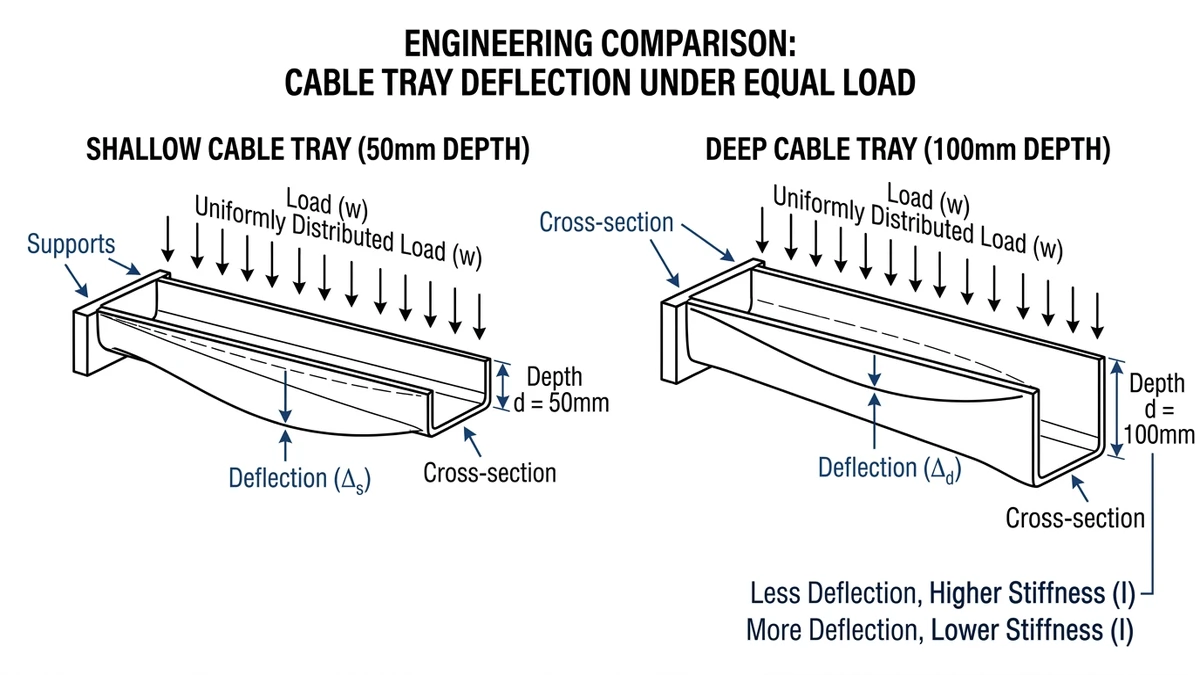
Increasing tray width increases both usable area and distributed load; if cable mass is 25 kg/m per 300 mm of width, moving from 300 mm to 600 mm roughly doubles load from 25 kg/m to 50 kg/m on the same span. Since a ladder tray behaves like a beam (M ≈ wL²/8), this higher load significantly increases midspan bending moment and deflection, so wider trays often require higher load‑class profiles, reduced support spacing, or stronger hangers, and beyond about 600–750 mm width structural checks typically govern span more than fill ratio.
Depth: Cable Fill, Layering, and Local Stiffness
Depth (commonly 50, 75, 100, 150 mm) governs cable layering and side‑rail stiffness. Deeper trays permit more stacking, but effective fill is usually limited to about 40–60 % of internal depth to maintain ventilation and avoid compressing lower layers (e.g., a 100 mm deep tray may be limited to ~60 mm cable stack), while increased depth improves rail section modulus and resistance to vertical and lateral loads, so depth is best set from cable diameter and layering needs, then checked against structural demands and accessibility.
Figure 1. Cross-sectional schematic defining internal cable tray width and depth and indicating typical industrial size bands.
Typical Size Families for Ladder, Perforated, and Solid-Bottom Trays
Cable tray width and depth are grouped into size families so supports, fittings, and accessories can be standardized, with ladder, perforated, and solid‑bottom trays sharing similar width increments but differing in depth, loading range, and best‑fit applications.
Comparative Size Matrix by Tray Type
Typical nominal sizes (check against local catalogues and IEC 61537 / NEMA VE 1 options):
Tray type
Common widths (mm)
Common depths (mm)
Typical use focus
Design notes
Ladder
150, 200, 300, 400, 450, 600, 750, 900
50, 75, 100, 125
Power and mixed loads, long spans (3–6 m)
Widest width/depth range; high load‑class options up to ≥200 kg/m
Perforated (vented)
100, 150, 200, 300, 400, 450, 600
35, 50, 60, 75
Control/instrument, ventilated small power bundles
Limited depth at larger widths; fill constraints above ~300 mm width
Solid-bottom
50, 100, 150, 200, 300, 400, 450, 600
25, 35, 50, 60
Data, low‑noise, small control cables
Smaller depths; typically shorter spans (≤2.5–3.0 m) and lower loads
Design Consequences of Size Families
The choice is tray type plus width, depth, span, and cable type as one system, because size families dictate what load classes, spans, fittings, and accessories are realistically available for a given route.
Ladder Trays
Use ladder trays where loads are high (e.g., ≥40–60 kg/m), spans are long (3–6 m), or LV/MV power cables dominate and vertical drops or outdoor exposure demand high robustness. They are structurally efficient but give less containment for very small or loose cables, which may need extra tie‑offs or sub‑ducts.
Perforated Trays
Perforated trays suit mainly control and smaller power bundles with modest mass per meter where some airflow is needed and EMC or small‑cable support matters, typically on spans ≤3 m and depths ≤75 mm; at ≥300 mm width, limited depth and lower load classes often govern before width or fill ratio.
Solid-Bottom Trays
Solid‑bottom trays are used for data, instrumentation, or sensitive signal cables needing protection from falling debris or drips, where cable diameters and loads are small, but poor ventilation raises cable temperatures and usually requires derating, and shorter spans and lower load classes increase support count on long routes.
[Expert Insight]
– In mixed‑service corridors, moving heavy power cables from perforated trays to adjacent ladder trays and keeping perforated trays for light control wiring often reduces total support steel because the heavier tray carries load more efficiently.
– Under process equipment, solid‑bottom trays tend to accumulate dust and liquids; specifying inspection covers or drain provisions can substantially reduce outage time during cleaning.
Figure 2. Conceptual comparison of deflection at different spans for 50 mm versus 100 mm deep cable trays at equal width and loading.
Selecting Tray Width and Depth for Industrial Routes
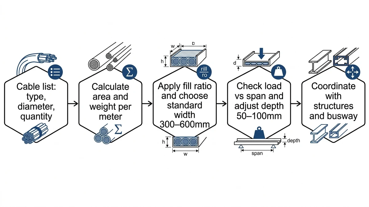
Selecting cable tray width and depth is a 3–5 step workflow starting from cable data, aiming for safe fill, adequate mechanical performance, and allowance for future expansion.
Step 1 – Define the Cable Set and Expansion Margin
List all cables on the route with diameter or flat width, mass per meter, and voltage/functional grouping (e.g., 400 V power, 24 V control, fieldbus). Then set an expansion margin, typically 20–30 % additional cross‑section for future circuits over 5–10 years, with 30 % more realistic where growth plans are defined.
Step 2 – Calculate Required Cable Area
Approximate area for each round cable as Area (mm²) ≈ π × (D/2)², sum all areas, and add the expansion margin. Translate this into a required laying width, then compare with usable tray width, bearing in mind that ladder and wire trays are commonly limited to about 40–50 % working fill of internal width (lower for perforated/solid‑bottom trays), so if cables occupy 260 mm at 40 % fill, a 300 mm tray is tight whereas 400 mm gives practical margin.
Step 3 – Select Tray Width from Fill Ratio
Pick the smallest standard width (e.g., 150, 200, 300, 400, 450, 600 mm) that keeps fill within the 40–50 % target while allowing segregation lanes and maintaining bend radius at fittings. Compare one wider tray with two narrower trays (e.g., one 450 mm vs. two 300 mm): a single wider tray means higher load per support but fewer supports and simpler routing, whereas twin trays improve segregation and access but need more steel and hangers.
Step 4 – Choose Depth Based on Cable Size and Route Conditions
Depth is driven by expected cable layering and route conditions: 50–75 mm often suffices for control and instrumentation cables, while large LV/MV power cables or multi‑layer routes need 100–150 mm, with deeper side rails beneficial for vertical runs, seismic or wind‑exposed locations, and clamp installation, but potentially intrusive indoors over frequently accessed equipment if not structurally required.
Step 5 – Check Load Class and Support Span
Estimate total linear load by summing cable mass per meter and adding allowances for covers, splice plates, and fittings (industrial power trays often end up around 40–80 kg/m), then check the selected tray series against manufacturer load tables and IEC 61537 or NEMA VE 1 guidance for the intended span, reducing spans or upgrading profiles if utilisation approaches about 70–80 % of rated capacity.
Figure 3. Practical selection workflow from cable list and load estimation to standard tray width, depth, and span verification.
For worked selection examples and dimensional rules of thumb, refer to Xinma’s guide on cable tray size calculation.
How Xinma Helps Coordinate Width, Depth, and Support Details in Specifications
Tray width, depth, and support spacing interact directly with cable fill, structural load, and ampacity, so a 400 mm wide, 75 mm deep tray at 2.5 m span behaves very differently from a 600 mm wide, 100 mm deep tray at 3.0 m span under the same load. Xinma focuses on coordinating these parameters so specifications are technically consistent and buildable.
Key risk patterns we see in tray specifications include overfilling shallow trays on main corridors, under‑designed spans for 600–900 mm wide trays reused with “standard” 3 m spacing, and omission of accessory loads, where covers, barriers, and splice plates can add 15–25 % to mass per meter.
Xinma’s engineering support typically includes:
Coordinated Tray Type and Size Selection
We assist in choosing between ladder cable tray, perforated, and solid‑bottom systems based on cable lists, fill ratios, EMC needs, and route conditions, often recommending ladder trays for high‑load main runs and perforated trays for short control branches while keeping widths and depths compatible with standard fittings and supports.
We verify that selected tray series and spans meet load and deflection limits for specified kg/m loading using manufacturer data and IEC/NEMA methodologies, and where utilisation is high we either suggest reduced support spacing, sometimes combined with seismic bracing components, or alternative profiles; tightening span from 3.0 m to 2.0 m on wide power trays has in some projects reduced measured deflection by over 40 %.
Integration with Fittings, Supports, and Busway
Width and depth choices are cross‑checked against fittings, reducers, vertical drops, and busway terminations so changes in direction and interfaces do not become weak points, and tray geometry remains compatible with busway connection instructions and required cable bend radii at tap‑off points.
For broader layout strategy, our article on cable tray systems and layouts discusses how different tray families integrate across a plant or building.
Detail-Level Coordination and Accessories
We help specifiers align tray selections with:
Covers, barriers, and dividers from our cable tray accessories range to meet EMC, fire, and segregation requirements.
Support design using guidance on cable tray support so wide and heavily loaded trays are neither over‑ nor under‑supported.
Documented tray load classes and span limits make late changes and maintenance approvals easier, because capacity is known rather than assumed; Xinma’s coordination work aims to establish these limits at design stage so contractors install a system aligned with project requirements.
If you want your next specification to treat cable trays as a coordinated system—width, depth, span, and accessories—rather than just a schedule of nominal sizes, Xinma can help validate selections, identify weak points, and adjust details before tender so that designs are both compliant and constructible.
For standardized tray definitions and performance logic, use the IEC 61537 publication page as the authority reference.
Frequently Asked Questions
How do I choose between ladder, perforated, and solid-bottom cable trays?
Select ladder trays for heavy or long‑span power runs, perforated trays for moderate loads with mixed power and control, and solid‑bottom trays where sensitive signal cables need protection from debris, then verify each choice against span, ventilation, and EMC requirements.
What is a reasonable fill ratio for industrial cable trays?
Many designers target 40–50 % of internal width as a working fill for ladder and perforated trays, which leaves space for heat dissipation, segregation, and future additions while staying within typical manufacturer recommendations.
How does cable tray depth influence cable derating?
Greater depth allows cables to be layered without exceeding side‑rail height, but higher stack height increases mutual heating, so deeper trays should still be evaluated with derating factors for multi‑layer arrangements rather than assumed to remove thermal limits.
When should I reduce cable tray support spacing?
Support spacing is usually reduced when tray width increases, total load per meter becomes higher than previous assumptions, or additional accessories such as covers and fire barriers are added, and the combination approaches the rated load or deflection limits.
Are there standard rules for maximum span length of cable trays?
Manufacturers typically publish tested load versus span tables, and designers select maximum span lengths from these rather than using a single “standard span,” adjusting for tray width, load class, and environmental loads such as snow or seismic effects.
Kevin Zheng
Kevin Zheng is a manager linked to Shanghai Xinma Busway & Cable Tray Co., Ltd. He writes technical content on cable tray systems, installation practice, sizing logic, load classes, and related standards for industrial and infrastructure applications.