Address
304 North Cardinal St.
Dorchester Center, MA 02124
Work Hours
Monday to Friday: 7AM - 7PM
Weekend: 10AM - 5PM
Address
304 North Cardinal St.
Dorchester Center, MA 02124
Work Hours
Monday to Friday: 7AM - 7PM
Weekend: 10AM - 5PM
Get premium quality cable management systems directly from the manufacturer.
Fill out the form below to receive our catalog and pricing.
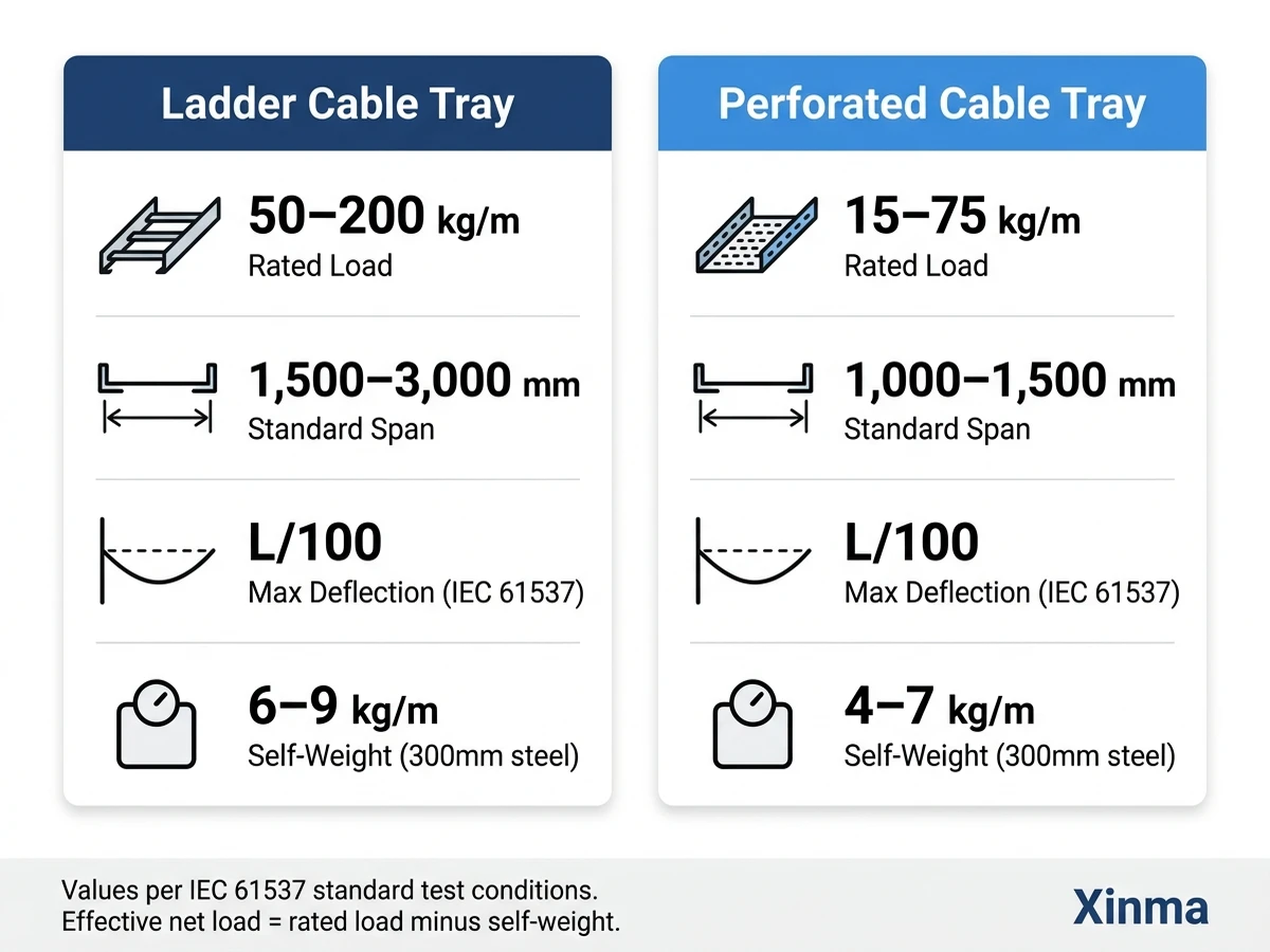
When comparing ladder cable tray vs perforated cable tray, the decision hinges on three measurable factors: load capacity, airflow around cables, and installation environment. Ladder trays carry heavier distributed loads — typically 75–200 kg/m under IEC 61537 Class C and Class D classifications — while perforated trays suit lighter cable management systems in the 25–75 kg/m range. That difference in structural geometry cascades into every downstream decision: span length, bracket count, ampacity derating, and long-term cable health.
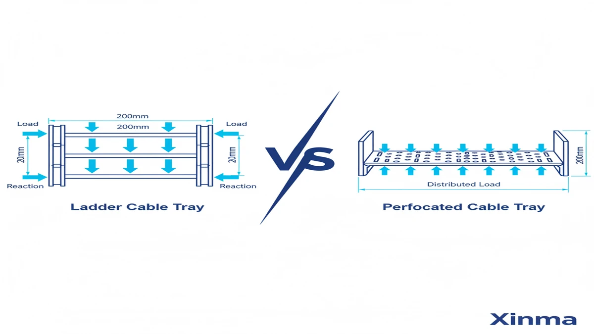
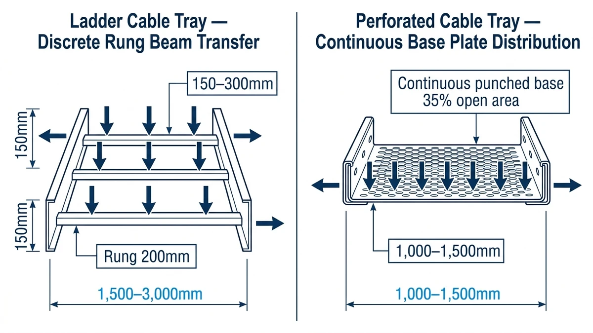
A ladder cable tray consists of two longitudinal side rails connected by transverse rungs spaced at fixed intervals, typically 150 mm or 300 mm on center. The rung spacing is the defining structural variable: 150 mm spacing increases bearing contact points per cable and reduces point stress on individual conductors, while 300 mm spacing cuts tray weight but limits support for smaller-diameter cables. Side rails — commonly formed from 1.5 mm to 3.0 mm cold-rolled steel or aluminum — carry the primary bending moment across the span. This I-beam-like geometry gives ladder trays their high load-to-weight ratio.
A perforated cable tray uses a continuous punched-sheet base welded or roll-formed between two side rails. The perforations — typically 20 mm × 10 mm oval punches covering 30–50% of the base surface — reduce material weight while maintaining some ventilation. Base thickness ranges from 1.0 mm to 2.0 mm. Because load distributes across the full sheet width rather than concentrating at discrete rungs, perforated trays support small-diameter cables and bundled wire groups more uniformly. The tradeoff: the sheet base acts as a flat plate in bending rather than a deep-section beam, which reduces allowable span and load class compared to ladder trays of equivalent material weight.
Load capacity is not simply a product specification — it derives from cross-sectional geometry, material thickness, span length, and support spacing working together. IEC 61537 governs cable management systems under the same load classification framework for both tray types, making it the primary standard for direct performance comparison between ladder cable tray and perforated cable tray.
IEC 61537 defines load classes as follows:
Each class requires that midspan deflection under proof load does not exceed L/100 for cable trays and L/200 for cable ladders, where L is the span between supports.
The deflection formula governing tray performance under uniform load is: δ = (5 × w × L⁴) / (384 × E × I), where w is load per unit length (N/mm), L is span (mm), E is Young’s modulus (≈ 200,000 N/mm² for steel), and I is the second moment of area of the tray cross-section (mm⁴). A deeper rail profile increases I significantly — doubling rail depth increases bending stiffness by a factor of 8.
At a 3-meter span, a 500 mm wide ladder tray in hot-dip galvanized steel typically achieves a safe working load of 90–120 kg/m while holding deflection within the IEC 61537 limit of span ÷ 200. The same span in a perforated tray of equivalent steel gauge generally supports 30–60 kg/m — adequate for instrumentation cable routing or structured data cabling, but insufficient for power feeder bundles in industrial plants.
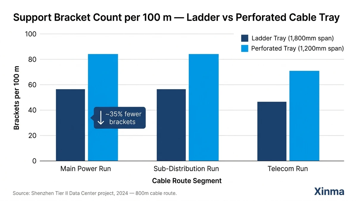
In a 2023 petrochemical facility project in Zhoushan, China (12,000 m² cable routing scope), engineers replaced an initial perforated tray specification with ladder trays on all feeder runs above 50 kg/m. The switch reduced support bracket count by 22% by allowing 1.5 m longer spans, cutting installed cost by approximately ¥180,000 on that scope alone.
[Expert Insight]
– Ladder tray rail depth has a disproportionate effect on stiffness: doubling depth from 75 mm to 150 mm increases the section modulus by roughly 4×, enabling the same steel weight to carry substantially heavier loads.
– A 2023 substation project in Guangdong selected 200 mm deep steel ladder trays at 3 m spans to carry 120 kg/m with midspan deflection under 10 mm — comfortably within the IEC 61537 Class C limit.
– Perforated tray’s flat-plate bending geometry makes it sensitive to span increases: a 20% increase in span can cut allowable load by up to 40% if deflection governs the design.
– Always verify load class at the actual project span, not the manufacturer’s default test span, which is often shorter than field conditions.
Ladder trays are the standard cable management solution for power cables above 25 mm² cross-section, outdoor runs exposed to wind and ice loading, and any environment where heat dissipation is critical. Perforated trays are preferred for control cable trays, signal wiring in clean rooms, and horizontal runs inside finished ceilings where debris accumulation must be minimized.
Thermal management is one of the most consequential differences between ladder cable tray and perforated cable tray, directly affecting cable ampacity and long-term insulation life. IEC 61537 governs both tray types but does not prescribe airflow requirements — that derating obligation falls under IEC 60364-5-52, which specifies correction factors when cables are grouped in enclosed or semi-enclosed cable management systems.
A ladder cable tray exposes cables on all four sides except where they rest on rungs, typically spaced 150–300 mm apart. This open geometry allows natural convection to remove heat from the cable bundle continuously. In a 2023 petrochemical plant upgrade in Guangdong province, engineers replacing solid-bottom trays with ladder trays on a 120 m power cable run recorded a 9°C reduction in measured cable surface temperature at peak load — enough to eliminate the 0.85 ampacity derating factor previously applied and recover approximately 12% additional current-carrying capacity per circuit.
Perforated cable tray occupies a middle ground. With perforation ratios typically ranging from 30% to 55% of tray floor area, it restricts airflow more than ladder tray but significantly outperforms solid-bottom tray. That partial ventilation benefits smaller-diameter signal and data cables, which generate less heat per unit length but benefit from bottom support across their full width.
A group of 12 × 25 mm² power cables installed in a ladder tray typically requires a grouping derating factor of 0.72–0.78, while the same cables in a perforated tray with ≥30% open area may require 0.68–0.74 depending on fill depth and ambient temperature. Ladder tray consistently yields 4–8% more usable ampacity under equivalent conditions — a measurable advantage in high-density power distribution runs exceeding 50 m.
For facilities routing primarily fiber optic, Cat6A, or instrumentation cables below 24 V, the thermal delta between the two tray types is negligible. The derating advantage of ladder tray is most pronounced for cables carrying sustained loads above 60% of rated current in ambient temperatures exceeding 35°C.
[Expert Insight]
– The ampacity recovery from switching to ladder tray can eliminate the need for a larger conductor cross-section — for example, stepping down from 35 mm² to 25 mm² on a 90 m run, with direct savings on copper cost.
– Derating stacks: grouping factor, ambient temperature factor, and installation method factor all multiply together. A perforated tray at 40°C ambient with 12 grouped cables can produce a combined derating of 0.55–0.60, sharply reducing effective circuit capacity.
– In data centers routing Cat6A above suspended ceilings, the thermal difference between ladder and perforated tray is practically immaterial — the derating advantage of ladder tray matters primarily for sustained power loads above 60% rated current.
– Always confirm the applicable clause of IEC 60364-5-52 for your specific cable grouping scenario; derating tables vary by installation method reference letter.
Choosing between ladder cable tray and perforated cable tray comes down to three quantifiable factors: load class, span interval, and cable fill density. Neither tray type is universally superior — the correct choice depends on what your cables weigh, how far apart your supports sit, and how much airflow your cable bundle requires.
Start with your calculated distributed load. Ladder trays are engineered to reach IEC 61537 Class C and Class D ratings — 150 kg/m and 200 kg/m respectively — across standard 3 m spans, because their longitudinal side rails transfer load directly to support points with minimal material between them. Perforated trays are optimized for Class A and Class B applications — typically 50–100 kg/m — where the perforated base provides sufficient stiffness without the structural depth a ladder rung system adds.
In a 2023 automotive assembly plant expansion in Chongqing (approximately 18,000 m² production floor), engineers initially specified perforated trays throughout. Load calculations showed cable bundles reaching 140 kg/m on main horizontal runs across 2.5 m spans. The main routing lines were redesigned using 150 mm deep ladder trays, reducing midspan deflection from an estimated 18 mm to under 7 mm — well within the IEC 61537 Class C deflection limit of L/200 (12.5 mm for a 2.5 m span). As a secondary benefit, the longer allowable spans also cut bracket installation labor by roughly 22%.
Once load class is satisfied, fill density determines ventilation needs. Perforated trays retain roughly 30–40% open area across the base — adequate for control cables, instrumentation wiring, and low-power data cables where heat dissipation is minimal. Ladder trays expose cable runs fully on three sides, making them the correct choice when ampacity derating must be minimized: particularly for power cables carrying more than 50 A per conductor in ambient temperatures above 35°C.
For facilities routing fiber optic, Cat6A, or instrumentation cables below 24 V, the thermal delta between the two tray types is negligible, and perforated tray is the more cost-effective solution.
Corrosive or outdoor environments with particulate exposure favor perforated tray — the closed base slows debris accumulation on cable jackets. Wet areas where water can pool are the opposite: standing water on a perforated base accelerates jacket degradation over time, and ladder tray’s open structure drains freely.
| Condition | Ladder Tray | Perforated Tray |
|---|---|---|
| Load ≥ 100 kg/m | ✓ Preferred | ✗ Not recommended |
| Span ≥ 2.5 m | ✓ Preferred | Marginal — verify deflection |
| Power cables > 50 A per conductor | ✓ Preferred | ✗ Derating risk |
| Control/data cables only | Acceptable | ✓ Preferred |
| EMI shielding required | ✗ Open structure | ✓ Better enclosure |
| Small-diameter cables (< 10 mm OD) | ✗ Sag risk between rungs | ✓ Full deck support |
| Water pooling risk | ✓ Drains freely | ✗ Pooling risk |
| Seismic zone application | ✓ Higher rigidity | Verify load class |
Apply the load class filter first. If your calculated cable load exceeds 100 kg/m at your intended span, ladder tray is the correct selection regardless of other factors. Below that threshold, and with cables primarily of the signal or control type, perforated tray delivers adequate support with simpler installation and lower unit cost.
A split specification — ladder tray for power feeders, perforated tray for instrumentation and data runs — is common practice in industrial projects and typically reduces total tray material cost by 12–18% compared to specifying ladder tray throughout, while satisfying all IEC 61537 load class requirements on both routing types.
For a closer look at how these systems integrate into broader cable management infrastructure, the cable tray systems overview covers material selection, finish options, and accessory compatibility across both tray families. Engineers specifying for corrosive or marine environments may also find the hot-dip galvanized cable tray guide useful alongside this comparison.
Related engineering references: industrial and commercial cable tray applications; dimension checks before procurement.
Ladder cable tray uses two deep longitudinal side rails bridged by transverse rungs, concentrating material where bending stress is highest and achieving high load-to-weight ratios. Perforated tray uses a continuous punched-sheet base that distributes load more evenly but offers lower bending stiffness across equivalent spans.
Ladder tray is generally the appropriate choice when cable fill weight exceeds roughly 100 kg/m, span spacing is 2.5 m or greater, or cables must be routed in high-ambient-temperature environments where ampacity derating is a design constraint. The open rung geometry provides superior convective cooling compared to a perforated base under those conditions.
Perforated tray can support power cables within its rated load class — typically IEC 61537 Class A or Class B — provided the calculated cable fill weight and span fall within the manufacturer’s verified capacity. For sustained high-current loads or larger conductor cross-sections, the restricted airflow through the perforated base may require additional ampacity derating compared to an equivalent ladder tray installation.
Span length directly governs midspan deflection, which IEC 61537 limits to L/200 for cable ladders under proof load. Ladder trays maintain compliance at longer spans because their deep rail profile resists bending more effectively than a perforated sheet base. For spans approaching or exceeding 3 m, verifying the specific tray’s certified load-class at that span is more reliable than relying on general range estimates.
Perforated tray can be used outdoors when specified with an appropriate corrosion protection finish — hot-dip galvanizing or marine-grade stainless steel — but its closed base can accumulate debris and retain moisture if drainage is not managed. Ladder tray’s open structure generally performs more predictably in wet or particulate-laden outdoor environments over the long term.
Yes. IEC 60364-5-52 requires grouping derating factors to be applied based on installation method, which differs between ladder tray and perforated tray due to differences in airflow geometry. In practical terms, a group of power cables in a ladder tray may carry 4–8% more usable ampacity than the same cables in a perforated tray of equivalent fill ratio, depending on ambient temperature and cable count.
A common approach routes medium-voltage and heavy power feeders on ladder tray — where load density and thermal derating govern — while instrumentation loops, BMS wiring, and data infrastructure use perforated tray on the same floor or zone. This split typically reduces total tray material cost by around 12–18% compared to specifying ladder tray throughout, while meeting IEC 61537 load class requirements on every routing segment.
