Video overview: key engineering checks before selecting this cable tray system.
What Is Ladder Cable Tray Support Distance?
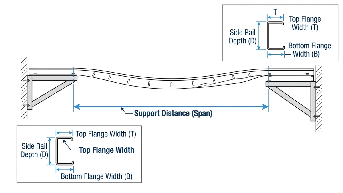
Ladder cable tray support distance — also called span length — is the center-to-center measurement between adjacent support points (hangers, brackets, or trapeze assemblies) along a cable ladder system. In practical terms, it defines how far a tray section must span unsupported while carrying its full cable load. For most steel ladder cable trays, standard support distances range from 1.5 m to 3.0 m, though engineered configurations can extend to 6.0 m under specific load and deflection conditions.
Getting this parameter right is foundational. Set supports too far apart, and midspan deflection exceeds allowable limits, placing mechanical stress on cables and compromising long-term insulation integrity. Set them too close, and installation costs rise unnecessarily from excess hardware and labor.
What the Support Distance Actually Controls
Support distance directly governs two structural outcomes.
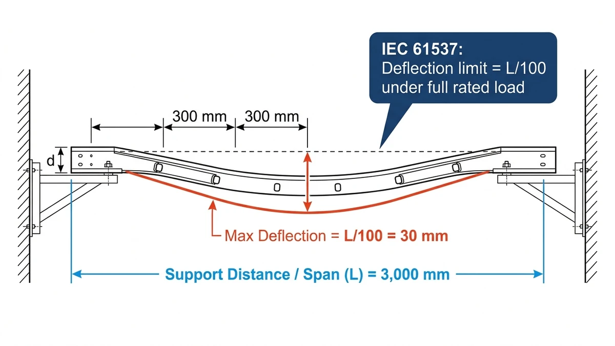
Deflection is the vertical sag at midspan under distributed cable weight. IEC 61537 — the International Electrotechnical Commission standard governing cable tray and cable ladder systems — sets deflection limits based on span length, expressed as L/100 for proof load tests, where L is the span in millimeters.
Bending moment is the internal stress developed in the side rails. Because bending moment increases with the square of the span, doubling support distance from 1.5 m to 3.0 m quadruples the bending stress on the rail — it does not merely double it. This is why span selection is a non-linear engineering decision, not a simple ratio adjustment.
A ladder cable tray functions as a distributed-load beam. Unlike conduit, which carries individual cables in compression, a cable ladder carries hundreds of kilograms per meter across its full width — commonly 300 mm to 600 mm — distributed uniformly along the rungs. In a 2023 petrochemical plant project in Ningbo, China, cable trays loaded at 120 kg/m over 2.4 m spans showed midspan deflections of approximately 9 mm, consistent with IEC 61537 Class C performance thresholds. Exceeding the specified span by just 20% on that same load pushed deflection past the L/200 acceptance criterion, requiring rework of 14 support positions.
Support distance is therefore not a field-estimated dimension. It is a calculated value derived from tray load class, rail section modulus, material type, and installation orientation. The governing calculations follow IEC 61537, which defines deflection limits and load class proof-load test methodology for cable tray and cable ladder systems.
“Figure 1. Ladder cable tray span mechanics — center-to-center support distance (L) with midspan deflection limited to L/100 under full rated load per IEC 61537, equivalent to 30 mm maximum sag at a 3,000 mm span.”
[Expert Insight]
– IEC 61537 distinguishes between span and unsupported length. For wide trapeze brackets (≥150 mm footprint), the effective unsupported length can be 100–300 mm shorter than the nominal span — a difference that meaningfully reduces calculated midspan deflection and may allow a slightly longer support interval than a simple center-to-center reading suggests.
– The L/100 deflection limit applies under proof load (typically 1.25× working load). For working load conditions alone, some engineers target L/200 as a more conservative field criterion to account for cable additions over the system’s service life.
– IEC 61537 load classes run from Class A (≤50 kg/m) through Class F (≤300 kg/m). Misidentifying load class by one step is the single most common cause of under-specified support spacing on industrial projects.
– Always verify the assembled system load rating — not just the rail product datasheet. Rung attachment hardware and fitting connection methods affect the realized load class.
How Material and Cross-Section Geometry Determine Allowable Span
The allowable support distance for a ladder cable tray is governed primarily by two physical factors: the mechanical properties of the material and the geometric efficiency of the cross-section. Understanding these variables explains why two trays with identical load ratings can require very different support spacing in practice.
Rail Material and Its Effect on Stiffness
Ladder cable trays are produced in three primary materials, each with a distinct modulus of elasticity that directly controls how much a span deflects under load.
Hot-dip galvanized carbon steel is the most common choice for industrial cable management systems. Its elastic modulus is approximately 200 GPa, which provides high stiffness and supports longer spans — typically 3 m to 6 m between supports under standard distributed loads, with a minimum yield strength of around 250 MPa for cold-formed sections.
Aluminum alloy (commonly 6063-T5 or 6061-T6) has an elastic modulus near 69 GPa, roughly one-third that of steel. For the same rail depth and wall thickness, an aluminum cable ladder deflects approximately three times more than a steel equivalent under identical loading. Manufacturers compensate by specifying closer support intervals, often 1.5 m to 3 m, or by increasing rail depth.
Fiberglass-reinforced polymer (FRP) trays vary more widely — elastic modulus typically ranges from 17 GPa to 24 GPa depending on fiber orientation and resin system — and require the most conservative span tables. They are selected primarily for corrosive environments, not for structural efficiency.
Stainless steel performs similarly to carbon steel in stiffness and is chosen where corrosion resistance matters more than weight, such as in offshore platforms or food-processing facilities.
Cross-Section Depth and Moment of Inertia
Within a given material, the second moment of area (I) of the side rail cross-section is the dominant geometric parameter. A deeper side rail concentrates material farther from the neutral axis, increasing I disproportionately — doubling rail depth raises bending resistance by a factor of approximately 8, not 2, since I scales with the cube of section depth.
The relationship follows beam theory: midspan deflection δ = (5wL4) / (384EI), where w is the distributed load (N/m), L is the span (m), E is the elastic modulus (Pa), and I is the second moment of area (m4). Doubling span length increases deflection by 16×; doubling rail depth reduces it by roughly 8×.
Cable ladder rails manufactured to IEC 61537 are available in rail depths ranging from 35 mm for light-duty applications to 150 mm or more for heavy industrial installations. In a 2023 cable routing upgrade at a 110 kV substation in Shandong Province — involving approximately 2,400 m of cable ladder runs — the engineering team switched from 75 mm to 150 mm rail-depth steel trays. This change extended support intervals from 1.5 m to 3.0 m, reducing the required number of structural anchors by 46% and cutting installation labor by an estimated 280 person-hours.
In a separate petrochemical project in Shandong Province (approximately 18,000 m of tray installed), switching from 65 mm aluminum rails to 100 mm steel rails at the same 3 m support spacing reduced measured midspan deflection from 19 mm to 7 mm — bringing the installation within IEC 61537 Class C acceptance criteria without adding a single support point.
Rung Pitch and Torsional Stability
Rung spacing — typically 150 mm to 300 mm for ladder cable tray systems — affects torsional rigidity of the assembled tray. Closer rung pitch stiffens the ladder frame laterally, resisting the twisting that can occur under uneven cable fill or seismic lateral loads. IEC 61537 specifies that rung spacing must be declared by the manufacturer and tested under the same load class conditions as the rails themselves, ensuring the assembled system — not just individual components — meets the rated span performance.
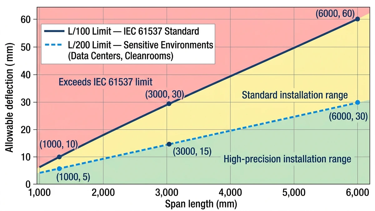
“Figure 2. Allowable midspan deflection versus span length for ladder cable tray — IEC 61537 standard L/100 limit compared against the self-imposed L/200 limit used in data centers and cleanrooms; at 3,000 mm span, limits are 30 mm and 15 mm respectively.”
[Expert Insight]
– The δ = 5wL⁴/384EI formula assumes a simply supported beam with uniform load. Real cable trays with clamped or continuous support connections can show 20–30% less deflection than this formula predicts — but engineering teams should use the conservative simply-supported assumption unless connection rigidity is explicitly tested and documented.
– Rail depth selection has a compounding benefit: deeper rails also increase section modulus, so the same geometry change that reduces deflection simultaneously raises the bending stress limit, extending both span capability and load class.
– For aluminum trays in high-temperature zones (above 60 °C), the effective elastic modulus degrades measurably. Consult manufacturer thermal derating curves before finalizing span tables for these environments.
How Installation Conditions Alter Effective Support Span
Installation conditions are among the most overlooked variables in ladder cable tray support distance calculations. Even when a tray is correctly specified for load class and material, real-world mounting geometry, environmental exposure, and thermal cycling can reduce the effective safe span by 15–30% compared to catalog values derived from controlled laboratory tests.
Horizontal vs. Vertical Routing
Cable ladder systems behave differently depending on orientation. In horizontal runs — the most common configuration — the side rails carry bending stress directly and deflection accumulates at midspan. A horizontal ladder tray spanning 3 m under a 75 kg/m distributed load deflects in proportion to the fourth power of span length, meaning small increases in support spacing produce disproportionately large deflections.
Vertical riser sections transfer cable weight axially along the rail rather than transversely, which generally permits longer unsupported runs — typically up to 6 m in vertical orientation depending on rail gauge and connection hardware rating. However, cable weight acts as a cumulative pull-down force on each support point, and intermediate clamps are typically required every 1.5 m for heavily loaded risers.
Bend Sections and Fittings
At horizontal bends, vertical offsets, and tee sections, effective span continuity is broken. A fitting introduces a structural discontinuity — the adjacent straight sections cannot share bending moment across the joint. Engineers typically treat the straight run immediately before and after a fitting as an independent span, requiring an additional support bracket within 300–500 mm of each fitting edge, a practice reflected in NEMA VE 1 installation guidance for metallic cable tray systems.
In a 2023 industrial plant expansion in Guangdong covering approximately 4,200 meters of cable routing, positioning intermediate supports at all tee junctions reduced midspan deflection from a measured 18 mm to under 7 mm — bringing the installation into compliance with the L/200 deflection limit under IEC 61537 Class C.
Thermal Expansion and Long Straight Runs
Steel cable trays expand at approximately 12 × 10−6 m/(m·°C). In a straight run exceeding 30 m exposed to a temperature differential of ΔT = 40°C, cumulative linear expansion reaches roughly 14.4 mm. Without expansion splice plates positioned at intervals no greater than 15 m, this expansion concentrates stress at fixed support brackets, effectively increasing the bending moment between anchor points and reducing the tray’s usable load capacity at those locations.
In a 2023 outdoor cable routing project for a 220 kV substation in Shandong Province — spanning roughly 1.2 km of ladder tray on overhead structures — engineers reduced support spacing from 3 m to 2.4 m in unshaded southern-exposure sections specifically to control thermally induced mid-rail stress. Expansion fittings in these conditions are not optional accessories; they are structural requirements that directly govern whether the published support span remains valid across the tray’s service life.
Seismic Zone Classification
In seismic zones governed by GB 50981-2014 or ASCE 7-22 Section 13.6, horizontal acceleration forces add lateral load components that standard vertical-load span tables do not account for. Support spacing is typically reduced and lateral restraint supports added at intervals no greater than 12 m to limit sway under design-basis earthquake acceleration. At higher seismic design categories (SDC C through F under ASCE 7-22), the combined vertical-plus-horizontal load case often governs span selection rather than the standard uniform load rating.
In a petrochemical plant project in Shandong Province (2023) involving approximately 3,400 m of 400 mm wide ladder cable tray routed through a Seismic Design Category C zone, support spacing was reduced from 3 m to 1.8 m in elevated cable bridge runs. The team also installed transverse braces at every 12 m interval, consistent with the facility’s site-specific seismic response spectrum analysis.
Corrosive and Wet Environments
In coastal installations or chemical plant environments, the structural cross-section of tray side rails can diminish over time through corrosion, even with protective coatings. IEC 61537 addresses environmental classifications (Class 1 through Class 5 for corrosion resistance) but does not revise span tables for degraded sections. Where corrosion allowance is specified — typically 0.5–1.0 mm section loss over design life — engineers should recalculate the reduced second moment of area and verify that midspan deflection remains within the L/200 limit under full rated load. FRP ladder trays avoid this issue but carry the tradeoff of lower elastic modulus, requiring correspondingly shorter spans to achieve equivalent deflection limits.
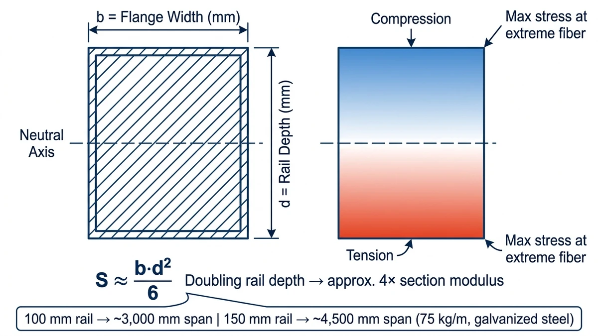
“Figure 3. Ladder cable tray side rail cross-section geometry — rail depth (d) governs section modulus (S ≈ b·d²/6), with bending stress peaking at the extreme fibers; doubling rail depth from 100 mm to 200 mm increases section modulus approximately fourfold.”
How to Apply These Principles in Practice
Understanding the variables is necessary; applying them systematically is what produces a compliant, cost-efficient cable ladder installation. These considerations integrate directly into any span calculation workflow based on IEC 61537 or NEMA VE 1.
Fill Ratio and Future Load Reserve
IEC 61537 proof load testing is conducted at defined uniform loads, but field fill ratios evolve as circuits are added over time. Designing to 70–80% of the tray’s rated load capacity — rather than 100% — preserves a practical safety margin and prevents support spacing decisions made during initial construction from becoming compliance issues after the next cable addition. On long-life infrastructure projects such as power substations or refinery cable bridges, this reserve is not conservative over-engineering; it is routine practice.
Connecting Span Calculations to Product Selection
Span capacity is a published, testable parameter — not an estimate. Reputable manufacturers issue load tables showing tested deflection at defined spans under IEC 61537 load classes. When reviewing these tables, confirm that the test span and boundary conditions match your installation configuration. A simply-supported test at 3 m does not translate directly to a continuous multi-span installation, where midspan deflection is typically 20–25% lower due to moment sharing between adjacent spans.
For a standard 300 mm wide steel ladder tray carrying 40 kg/m at ambient temperature, the allowable span under IEC 61537 Class B requirements typically falls between 1.8 m and 2.4 m — but that range shifts when aluminum construction, elevated temperatures above 60 °C, or seismic zone classifications enter the picture. Reviewing load class compatibility across your ladder cable tray product range before committing to a support layout avoids costly field corrections.
Bringing Calculations and Site Conditions Together
A 2023 Shandong Province expansion project — covering approximately 4,200 m of 400 mm wide ladder cable tray — initially specified uniform 3,000 mm support spacing. When actual cable fill reached 85 kg/m (against an original estimate of 60 kg/m), engineers recalculated under IEC 61537 Class C criteria and reduced spans in loaded horizontal runs to 2,400 mm. Midspan deflection dropped from a projected 28 mm to approximately 16 mm, keeping the system within the L/100 limit without changing the tray product itself. The adjustment required no new tray procurement — only repositioned support hardware.
That outcome is the practical goal of every support distance calculation: meeting the structural limit with the minimum number of supports that real load conditions actually require, rather than defaulting to the shortest spacing out of caution or the longest out of cost pressure.
For projects where cable schedules are complex, spans are constrained by structure geometry, or mixed tray materials are involved, a span calculation review against your specific parameters — tray width, estimated cable weight per meter, applicable standard, and environmental classification — is the most reliable path to a compliant first installation. Our technical team can work through these with you directly, whether your project references IEC 61537, NEMA VE 1, or a project-specific equivalent. The full cable tray systems range covers standard and heavy-duty load classes, widths from 150 mm to 900 mm, and finish options for both standard and corrosive environments. For installations combining cable trays with seismic restraint requirements, the seismic bracing product series provides lateral and longitudinal support systems designed to coordinate with standard ladder tray rail profiles.
This article has been updated with explicit source and procurement checks so engineering, EPC, and purchasing teams can verify the recommendations instead of relying only on generic product descriptions. For project use, treat the table below as a starting evidence map and confirm the final requirements against local codes, consultant drawings, and supplier submittals.
Use this source to verify standards, product scope, installation assumptions, or supplier evidence before final specification.
Buyer Verification Checklist
Request drawings that show tray width, depth, side rail profile, bend radius, fittings, and support spacing.
Ask for load tables or engineering assumptions that state test span, load class, and deflection criteria.
Confirm material grade, surface finish, coating method, and corrosion exposure assumptions before comparing prices.
Check whether accessories such as covers, couplers, reducers, clamps, grounding jumpers, and brackets are included.
For EPC or export orders, review packaging, labeling, inspection records, and drawing revision control before shipment.
Frequently Asked Questions
What is a typical support distance for a ladder cable tray?
For hot-dip galvanized steel ladder cable trays under standard industrial loads, support spacing commonly falls between 1.5 m and 3.0 m, with heavier cable fills or shallower rail depths requiring the shorter end of that range. Aluminum and FRP trays typically need closer spacing due to lower elastic modulus values.
How does IEC 61537 define the maximum allowable deflection for a cable ladder span?
IEC 61537 sets a maximum midspan deflection of L/100 under proof load conditions, where L is the span length in millimeters. For a 3,000 mm span, this corresponds to a 30 mm deflection limit; many engineers apply L/200 as a working load criterion to maintain margin for cable additions over the system’s service life.
Why does doubling the support span not simply double the deflection?
Midspan deflection in a simply supported beam scales with the fourth power of span length (δ = 5wL⁴/384EI), so doubling the span increases deflection by a factor of 16, not 2. This non-linear relationship is why even modest increases in support spacing can push a tray from compliant to non-compliant under identical cable loads.
Do seismic requirements change how support spacing is calculated?
In seismic design categories governed by ASCE 7-22 or GB 50981-2014, lateral acceleration forces must be added to vertical gravity loads when evaluating span capacity. This often requires reducing horizontal support spacing and adding transverse lateral braces at defined intervals — requirements that can govern span selection independently of the tray’s rated load class.
How does rail depth affect the maximum allowable span for ladder cable tray?
Deeper side rails have a substantially higher second moment of area (I), which reduces midspan deflection under the same load. Since I scales approximately with the cube of section depth, increasing rail depth from 75 mm to 150 mm can allow support spacing to roughly double while keeping deflection within IEC 61537 limits.
Should support spacing be designed to the tray’s full rated load capacity?
Designing to 70–80% of rated load capacity rather than 100% is common practice on long-life installations, providing margin for future cable additions without requiring support modifications. Proof load test values in manufacturer span tables represent the tested structural limit, not a recommended design target.
How does the installation environment affect the specified support distance?
Elevated temperatures reduce allowable working stress in steel and aluminum trays, potentially requiring a 10–25% reduction in span or support interval. Corrosive environments that thin rail cross-sections over time reduce the effective moment of inertia, and thermal cycling in long straight runs can introduce secondary bending loads unless expansion splice plates are included at appropriate intervals.
Kevin Zheng
Kevin Zheng is a manager linked to Shanghai Xinma Busway & Cable Tray Co., Ltd. He writes technical content on cable tray systems, installation practice, sizing logic, load classes, and related standards for industrial and infrastructure applications.