Video overview: key engineering checks before selecting this cable tray system.
How to Choose a Ladder Cable Tray for Industrial Projects
Choosing the right ladder cable tray comes down to four core parameters — load class, material, width, and span — matched precisely to your cable routing conditions. Get this selection wrong and you risk midspan deflection failures, accelerated corrosion, or expensive rework after installation.
Ladder cable trays are the preferred cable management system for heavy industrial environments because their open rung design allows unrestricted airflow around power cables, directly supporting the ampacity derating calculations required under IEC 61537 (the governing standard for cable tray systems and cable ladder systems). In a petrochemical plant expansion in Shandong Province (2023) covering 4.2 km of cable routing, switching from solid-bottom trays to ladder trays reduced cable derating factors by an average of 12% — allowing engineers to specify one conductor size smaller on 38% of power cable runs, a material saving of approximately ¥680,000.
What This Guide Covers
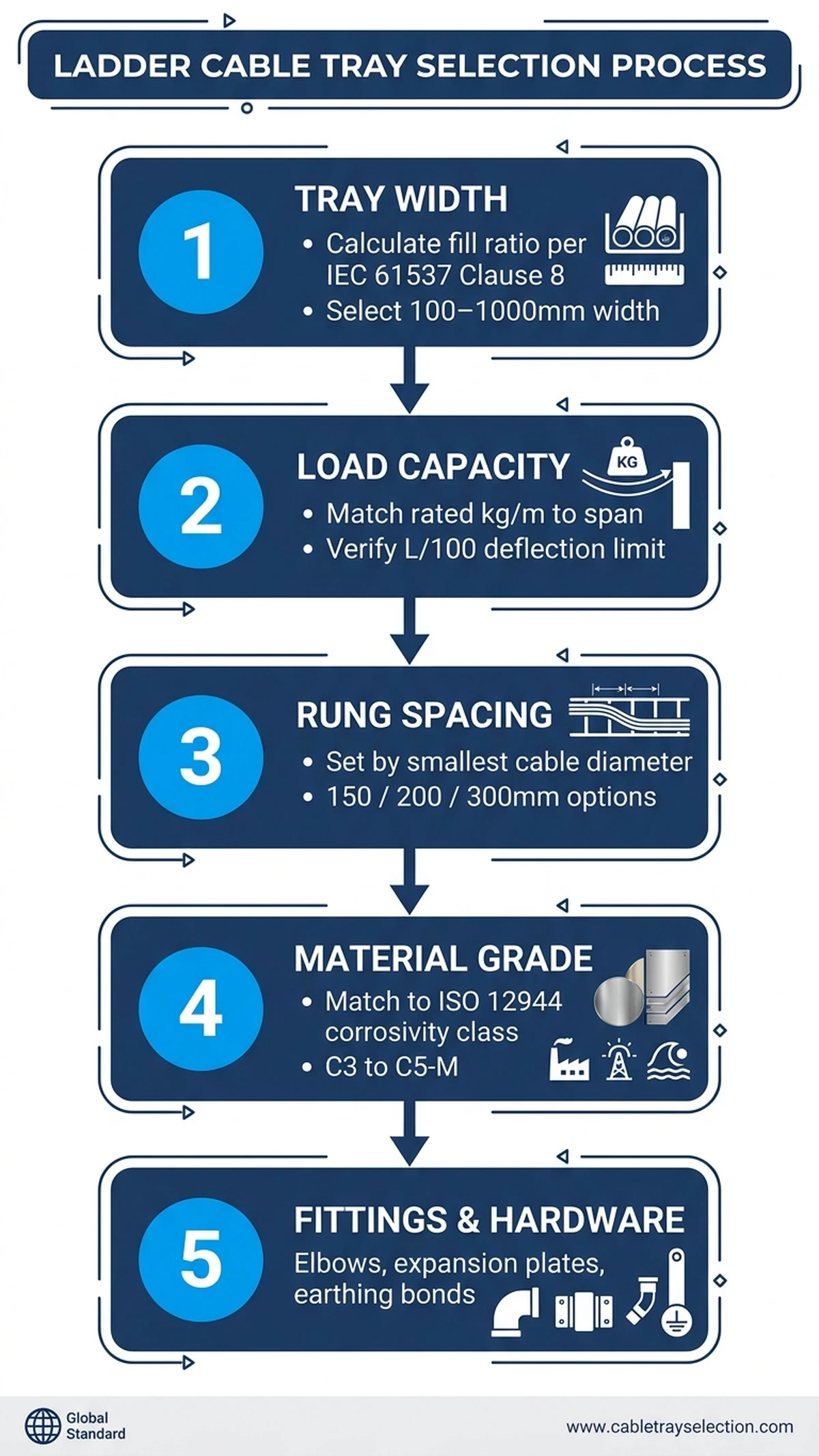
This buyer guide walks through every decision a project engineer or procurement manager must make before specifying a ladder cable tray:
Load class selection — matching IEC 61537 Class A through D ratings (50 kg/m to 200 kg/m) to your cable fill schedule
Material choice — hot-dip galvanized steel, stainless steel (304 or 316L), aluminum alloy, or fiberglass reinforced plastic (FRP), each with distinct corrosion resistance and weight trade-offs. The ladder cable tray product series covers all standard load classes and material options
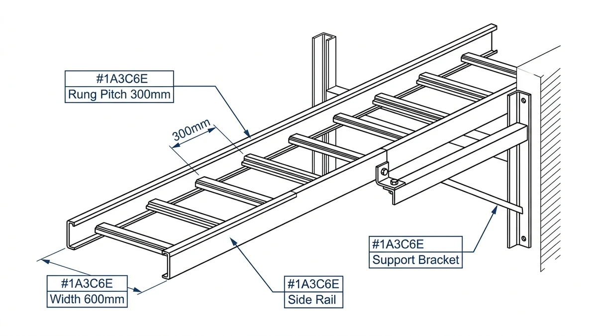
Tray width and rung spacing — standard widths from 100 mm to 900 mm, with rung pitch typically at 300 mm centers for power cables
Span and support intervals — directly controlling midspan deflection, the critical structural parameter defined in IEC 61537 Clause 8
Finish and coating requirements — driven by environmental zone classification (indoor dry, outdoor, chemical, or marine)
This guide is written for electrical engineers, EPC contractors, and industrial procurement teams specifying cable management systems for power plants, oil and gas process areas, manufacturing facilities, and large infrastructure projects. Selection criteria apply equally to North American NEMA VE 1 specifications and IEC-aligned international projects.
**
How Ladder Cable Trays Work: Load Mechanics and Structural Principles
A ladder cable tray consists of two parallel side rails connected by transverse rungs — a structure that supports and routes power and control cables across open spans. Understanding the load mechanics is essential before selecting the right product.
The primary engineering challenge is accounting for the full range of loads the system must carry. Cables exert a uniformly distributed load across each span; a typical 300 mm wide ladder tray filled with medium-voltage power cables can carry between 30 kg/m and 75 kg/m depending on cable diameter and fill arrangement. Static cable weight is only part of the picture. Beyond it, engineers must factor in:
Concentrated point loads from cable joints or splice boxes, typically 50–150 kg per location
Thermal expansion forces as aluminum or steel rails contract and expand with ambient temperature swings of ±40 °C in outdoor industrial environments
Seismic acceleration forces in facilities classified under IEC 61537 or ASCE 7-22 seismic design categories
Span, Deflection, and IEC 61537 Load Classes
IEC 61537 governs load classification and deflection limits for ladder trays. Load classes run from Class A (50 kg/m) through Class D (200 kg/m), with each class specifying a maximum allowable midspan deflection of L/200 under proof load — meaning a tray spanning 3 m may not deflect more than 15 mm under rated load.
In the same Shandong petrochemical expansion, specifying Class C ladder trays at 600 mm width with 3 m spans reduced support steel requirements by 22% compared to the original design using 1.5 m spans, while maintaining full deflection compliance under a 120 kg/m cable load. Rung spacing also matters here. Standard 300 mm pitch suits most power cables with outer diameters above 25 mm; 200 mm spacing is recommended for flexible or smaller-diameter cables to prevent localized bending stress from exceeding the cable manufacturer’s minimum bend radius.
[Expert Insight]
– IEC 61537 Clause 8 proof-load testing applies a 1.25× multiplier over the declared UDL — so a Class C tray rated at 150 kg/m must sustain 187.5 kg/m without permanent deformation exceeding L/200.
– Thermal expansion in steel rails runs approximately 12 mm per 10 m at a 40 °C temperature delta; expansion splice plates must be positioned at intervals no greater than 30 m in outdoor installations to prevent rail buckling.
– In seismic zones, lateral bracing at 6 m intervals (per ASCE 7-22 Chapter 13) is typically required regardless of load class — confirm with the structural engineer of record.
– Always distinguish between “proof load” (structural integrity check) and “working load” (service condition); using proof load figures as design load is a common — and dangerous — specification error.
Selecting the Right Material: Steel, Aluminum, or Fiberglass
Material selection is one of the most consequential decisions in any ladder cable tray project. The wrong choice can accelerate corrosion, overload support structures, or violate site safety codes — all of which create costly remediation. Three materials dominate the market: carbon steel, aluminum alloy, and fiberglass-reinforced polymer (FRP). Each serves distinct environments and load requirements.
Carbon Steel (Hot-Dip Galvanized)
Hot-dip galvanized carbon steel remains the default for heavy industrial cable routing where mechanical strength is the primary concern. Steel ladder trays typically achieve load class ratings up to 200 kg/m (IEC 61537 Class D), making them suitable for dense power cable fills in petrochemical plants and heavy manufacturing. The hot-dip process deposits a zinc layer of 45–85 µm, bonded metallurgically to the base steel per EN ISO 1461, providing 20–30 years of protection in C3 (medium corrosivity) environments.
In a 2023 ammonia plant expansion in Shandong Province, galvanized steel ladder trays spanning 3 m carried cable bundles averaging 140 kg/m without exceeding the IEC 61537 L/200 deflection limit. The primary liability is corrosion resistance: in environments with relative humidity above 80% or chloride-laden atmospheres — coastal sites, chemical process areas — standard galvanizing degrades within 5–8 years without supplemental epoxy coating or stainless fasteners.
Aluminum Alloy (6063-T5 or 6061-T6)
Aluminum trays offer a 65–70% weight reduction versus comparable steel sections, reducing both structural support costs and installation labor. Alloy grade 6063-T5 provides adequate structural performance for spans up to 3 m at moderate loads (typically up to 75 kg/m); anodized or chromate-treated finishes extend service life in mildly corrosive zones.
Aluminum is the preferred choice for data centers, food processing facilities, and offshore platforms where weight loading on raised floors or grating structures is constrained. Its limitation is galvanic compatibility: aluminum must be isolated from carbon steel supports using dielectric sleeves or neoprene pads to prevent accelerated corrosion at contact points. Environments with regular alkaline or acidic wash-down at pH below 4 or above 9 attack the oxide layer and disqualify aluminum entirely.
Fiberglass-Reinforced Polymer (FRP)
FRP ladder trays are specified in highly corrosive environments — wastewater treatment plants, offshore oil platforms, battery rooms, and ATEX/IECEx Zone 1 areas — where metallic trays create unacceptable risks. FRP is non-conductive, non-magnetic, and resistant to a broad range of chemicals at continuous operating temperatures up to 130 °C for standard polyester resin systems. Load capacity is lower than steel, generally capped at 75–100 kg/m, so structural calculations must be verified against the manufacturer’s certified load tables. The trade-off is cost and stiffness: FRP typically runs 30–40% higher unit cost than galvanized steel and requires support spacing no greater than 1.5 m versus 3 m for steel.
Material Selection Summary
Material
Max Load Class (IEC 61537)
Best Environment
Key Limitation
Galvanized Steel
Class D (200 kg/m)
General industrial / outdoor
Corrosion in wet/chemical zones
Aluminum 6063-T5
Class B–C (75–150 kg/m)
Lightweight / clean facilities
Galvanic corrosion risk
FRP
Class B–C (75–100 kg/m)
Corrosive / explosive areas
Higher cost, closer support spacing
Match material to the site’s corrosion classification first, then confirm structural adequacy against your calculated cable load per meter. The complete cable tray range covers steel, aluminum, and specialty options for all corrosion and load categories.
[Expert Insight]
– Galvanic corrosion between dissimilar metals is a field failure that rarely shows up in lab testing — specify isolation hardware (neoprene-lined clamps, plastic-tipped beam clamps) at every aluminum-to-steel interface and include it in the procurement scope.
– Pre-galvanized (electro-galvanized) steel carries only 8–20 µm zinc versus 45–85 µm for hot-dip; it is acceptable for dry indoor environments but should never be specified outdoors or in areas with regular condensation.
– 316L stainless steel is mandatory where chloride concentration exceeds 200 mg/m³ — the molybdenum addition (2–3%) provides pitting resistance unavailable in 304 grade.
– FRP tray deflection under load is approximately 1.5–2× that of equivalent steel sections; always request the manufacturer’s certified load-deflection curves, not just maximum rated load.
Sizing and Load Capacity: Matching the Tray to Your Cable Fill
Undersizing a ladder cable tray causes excessive fill ratios and heat buildup. Oversizing wastes material budget and inflates structural support costs. The path between those two failure modes runs through a disciplined calculation.
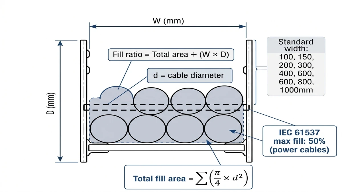
Calculating Required Tray Width
Tray width must accommodate the total cross-sectional area of all cables plus a mandatory clearance margin. IEC 61537 limits the cable fill ratio to 40% of the tray’s usable interior cross-section for general power cable applications. For a 150 mm wide × 50 mm deep ladder tray, usable cross-section is approximately 7,500 mm²; the 40% fill limit permits roughly 3,000 mm² of cable cross-section.
In a 2023 petrochemical plant upgrade in Zhejiang Province — involving 18 cable runs from 25 mm² to 240 mm² power cables — this calculation required upgrading from initially specified 200 mm trays to 300 mm trays, reducing future re-routing cost by an estimated 22%. Standard widths run 100 mm, 150 mm, 200 mm, 300 mm, 450 mm, and 600 mm. Always select the next width above your calculated fill, not the exact match, to preserve capacity for future cable additions.
Selecting the Right Load Class
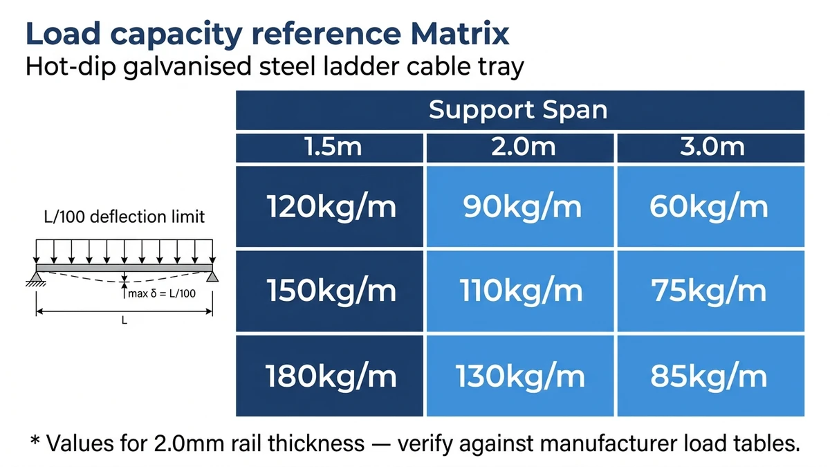
IEC 61537 defines load classes by the uniformly distributed load a tray must support at a given span without exceeding maximum permissible deflection (span ÷ 200):
IEC 61537 Load Classes
Load Class
UDL (kg/m)
Typical Span
Application
A
50
1.5 m
Light instrumentation
B
100
3.0 m
General process cables
C
150
3.0 m
Medium power runs
D
200
3.0 m
Heavy power and multi-core
For most industrial plants with 3 m support spacing, Class C or D is the standard selection. Specifying Class B on a 3 m span under a 120 kg/m actual load produces midspan deflection exceeding the L/200 limit — a compliance failure that simultaneously accelerates rung fatigue.
Accounting for Dynamic and Concentrated Loads
Static cable weight is only part of the load picture. Add 10–15% to your UDL calculation for cable joint boxes and pull-through tension during installation. In seismic zones classified under GB 50981 or ASCE 7-22, lateral acceleration multipliers can increase effective load demand by 0.3g–0.5g, requiring heavier rail profiles or reduced support spacing. Seismic bracing systems provide lateral and longitudinal restraint for ladder tray installations in seismic design categories C and above.
A petrochemical plant in Shandong (2023) that undersized tray load class by one tier experienced midspan deflection exceeding 18 mm over a 3 m span — surpassing the IEC 61537 L/200 limit — and required full rerouting within 14 months of commissioning. That single specification error added approximately ¥380,000 in unplanned rework.
**
Selecting the Right Finish and Coating for Your Environment
The wrong coating accelerates corrosion, inflates maintenance costs, and can compromise structural integrity within 3–5 years in aggressive environments. Finish selection follows directly from the site’s ISO 9223 corrosivity classification — measure or estimate atmospheric chloride deposition rate, sulfur dioxide levels, and humidity, then map to C1–C5 categories.
Hot-Dip Galvanized Steel
Hot-dip galvanizing (HDG) is the industry standard for outdoor and moderately corrosive environments. Per ISO 1461, the zinc layer (typically 45–85 µm) is bonded metallurgically to the base steel, providing 20–30 years of corrosion protection in C3 environments such as urban industrial atmospheres. In a coastal petrochemical project in Zhoushan, China (2023), specifying HDG trays with a 65 µm minimum zinc thickness extended the replacement interval from 7 years to a projected 22-year service life, cutting long-term material costs by approximately 40%.
Pre-Galvanized (Electro-Galvanized) Steel
Pre-galvanized steel carries a thinner zinc coating — typically 8–20 µm — applied before fabrication. This finish suits indoor, dry environments such as commercial buildings or climate-controlled equipment rooms. Cut edges and weld points lose coating protection, making pre-galvanized trays unsuitable where humidity exceeds 85% RH or where condensation is regular.
Stainless Steel (304 and 316L Grades)
Grade 304 handles mildly corrosive chemical environments; Grade 316L adds molybdenum (2–3%) for resistance to chloride-rich conditions — offshore platforms, food processing, and coastal installations. Stainless trays carry a significant cost premium (typically 3–4× HDG equivalent) and should be specified only where environmental data — chloride concentration, pH exposure, cleaning chemical contact — genuinely justifies the investment.
Powder-Coated Steel
Powder coating over HDG or pre-galvanized steel adds color-coding capability and an additional corrosion barrier, with coating thickness generally 60–80 µm. It is common in architectural or data center applications where cable management system aesthetics matter. Powder coat alone, without a zinc primer layer, should not be used in environments rated above C2 corrosivity per ISO 9223.
**
Lifetime Cost Analysis: Looking Beyond the Purchase Price
Purchase price is only one component of total ownership cost. A tray specified at $18/meter may generate far higher lifecycle costs than one at $28/meter when corrosion replacement, maintenance labor, and system downtime are factored across a 20–25 year service horizon.
Material Durability and Replacement Cycles
Material choice drives the largest share of long-term costs. Hot-dip galvanized steel trays in moderate industrial environments typically require recoating or partial replacement at 12–15 years, while 316L stainless steel installations in offshore or chemical processing environments routinely reach 25+ years with no structural intervention. In the Shandong petrochemical expansion (2023), switching from painted carbon steel to hot-dip galvanized tray on a 4,200-meter cable routing network reduced projected 20-year replacement costs by approximately 42%, despite a 31% higher upfront material cost. The arithmetic is straightforward — the premium pays back within the first replacement cycle.
Maintenance Labor Costs
The open design of ladder-type cable management systems is a structural maintenance advantage. Because cable fill is visible without removing covers, inspection time per 100-meter segment averages 15–20 minutes versus 35–50 minutes for enclosed duct systems. This difference compounds significantly across large installations with quarterly inspection requirements.
Oversizing load class quietly drives unnecessary cost in the other direction. Specifying Class D tray on a light-duty instrumentation run wastes material and increases structural support costs. A disciplined cable fill calculation — accounting for all cables at full fill plus a 20% reserve — typically confirms that Class B or Class C tray (100–150 kg/m capacity) covers the majority of industrial process plant runs.
Total Cost Comparison
**
Request lifecycle cost data — not just unit pricing — from suppliers. Reputable manufacturers including Legrand and OBO Bettermann publish technical selection guides that include estimated service life ranges by environment classification, enabling direct comparison across material grades on a cost-per-year-of-service basis rather than cost-per-meter. The cable tray size calculation guide provides a structured approach to confirming tray dimensions and fill ratios before procurement.
Summary: Key Selection Criteria at a Glance
Every ladder cable tray specification rests on five interdependent parameters. Confirm all five before issuing a purchase order — each one maps directly to a line item your procurement team will hand to the supplier.
Load Capacity and Span
Begin every selection with the design load calculation. Apply a safety factor of at least 1.5× to your calculated cable fill weight before assigning an IEC 61537 class. For spans exceeding 3 m, verify midspan deflection does not exceed L/200 under proof load. Always use the manufacturer’s published load-span tables, which are tested per IEC 61537 proof-load methodology — never extrapolate from shorter-span data.
Material and Corrosion Resistance
Hot-dip galvanized steel suits general industrial and outdoor environments. Stainless steel 316L is required where chloride exposure exceeds 0.5 mg/m²/day or where pH drops below 5. FRP applies in chemically aggressive zones where metallic trays would degrade within 5 years, and in ATEX/IECEx Zone 1 areas where conductivity is a hazard.
Tray Width and Cable Fill Ratio
Size tray width so the cable fill ratio stays at or below 40% of the usable cross-sectional area. A 600 mm wide tray accommodating 150 mm cable fill depth provides roughly 90,000 mm² of usable area — sufficient for medium-voltage power cable bundles in substation feeders without triggering ampacity derating concerns. Always select the next standard width above your calculated fill, not the exact match.
Coating and Finish
Electrostatic powder coating at ≥ 60 µm is adequate for indoor industrial use. Outdoor installations typically require hot-dip galvanizing to ≥ 85 µm per ISO 1461. Confirm coating thickness and adhesion standard from test reports, not just product data sheets.
Compliance and Certification
Confirm the tray system carries third-party certification to IEC 61537 or the applicable regional equivalent — NEMA VE 1 in North America, GB 31251 in China. For projects subject to seismic requirements, verify compliance with ASCE 7-22 or GB 50981 seismic bracing provisions before procurement. If any parameter cannot be confirmed from supplier documentation alone, request factory test certificates or commission an independent verification before finalizing the cable management system design.
How do I calculate the correct load class for a ladder cable tray?
Calculate the total weight of cables per meter of tray run using each cable’s published weight (kg/m), then apply a minimum 1.5× safety factor before selecting an IEC 61537 class — Class A (50 kg/m) through Class D (200 kg/m). Add 10–15% to account for cable joint boxes and pull-through tension during installation.
What rung spacing should I specify for power cables versus instrumentation cables?
Standard 300 mm rung spacing suits power cables with outer diameters of 25 mm or greater; instrumentation or smaller flexible cables generally benefit from 200 mm spacing to prevent localized sag and bending stress between support points.
When is fiberglass-reinforced polymer (FRP) tray the right choice over galvanized steel?
FRP is the appropriate choice in environments where metallic trays would degrade within approximately five years — typically chemical process areas with pH below 4 or above 10, offshore platforms with continuous salt spray, and classified explosive atmospheres where non-conductive cable management is a safety requirement.
How does the 40% cable fill rule affect tray width selection?
Keeping cable cross-sectional area at or below 40% of the tray’s usable interior cross-section preserves adequate airflow for ampacity derating calculations and leaves practical space for future cable additions without requiring a full tray replacement or re-routing exercise.
What is the difference between hot-dip galvanized and pre-galvanized steel tray?
Hot-dip galvanizing deposits a 45–85 µm zinc layer after fabrication, bonded metallurgically to the base steel and protecting cut edges; pre-galvanized (electro-galvanized) steel carries only 8–20 µm applied before fabrication, leaving cut edges and welds unprotected — making it suitable for dry indoor environments but not for outdoor or high-humidity applications.
How do I determine the maximum support span for a ladder cable tray installation?
Maximum span depends on the tray’s declared load class and the actual cable fill weight; the IEC 61537 deflection limit of L/200 at midspan is the governing criterion, and manufacturers publish tested load-span tables that should be used rather than calculated estimates, particularly for Class C and D installations above 100 kg/m.
Does material choice affect the grounding and bonding requirements for a cable tray system?
Aluminum and steel trays can both serve as equipment grounding conductors in many jurisdictions, but aluminum’s oxide layer may require bonding jumpers at splice joints to maintain continuous conductivity; FRP trays are non-conductive and require a separate grounding conductor run alongside the tray system in all cases.
Kevin Zheng
Kevin Zheng is a manager linked to Shanghai Xinma Busway & Cable Tray Co., Ltd. He writes technical content on cable tray systems, installation practice, sizing logic, load classes, and related standards for industrial and infrastructure applications.