Address
304 North Cardinal St.
Dorchester Center, MA 02124
Work Hours
Monday to Friday: 7AM - 7PM
Weekend: 10AM - 5PM
Address
304 North Cardinal St.
Dorchester Center, MA 02124
Work Hours
Monday to Friday: 7AM - 7PM
Weekend: 10AM - 5PM
Get premium quality cable management systems directly from the manufacturer.
Fill out the form below to receive our catalog and pricing.
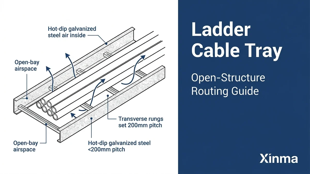
A ladder cable tray is an open-structure cable management system consisting of two parallel side rails connected by evenly spaced transverse rungs — resembling a horizontal ladder laid horizontally across a building or plant structure. It provides mechanical support for power cables, control cables, and instrumentation wiring across industrial, commercial, and infrastructure environments without enclosing them in conduit or solid-bottom trays. Where heat dissipation, cable accessibility, and future reconfiguration are engineering priorities, ladder tray is almost always the first option specified.
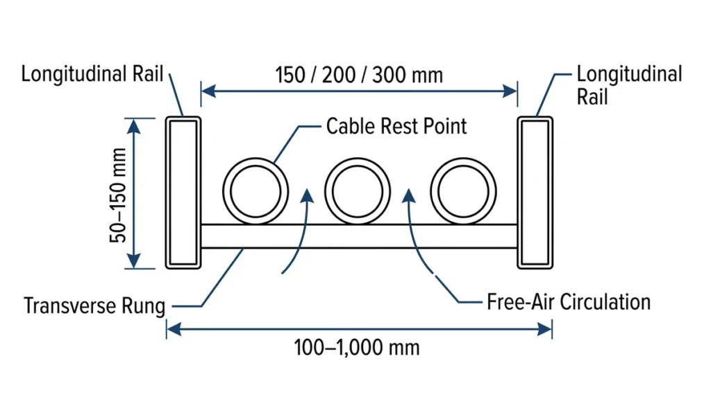
The defining geometry is straightforward: two longitudinal side rails, typically 75 mm to 150 mm in depth, span between support brackets at intervals generally ranging from 1.5 m to 3 m. Rungs are welded or bolted across the rails at 150 mm to 300 mm spacing, creating the open lattice that gives the system its name. Cable mass rests directly on the rungs — there is no continuous bottom surface — so air circulates freely around all cable surfaces. That open path is not incidental; it is the engineering rationale for selecting open-rung tray configurations over solid-bottom alternatives.
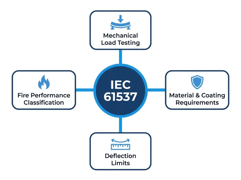
IEC 61537 (Cable management — cable tray systems and cable ladder systems), published by the International Electrotechnical Commission, governs mechanical performance, load classification, and test requirements for these systems. Standard tray widths run from 150 mm to 900 mm, with 300 mm and 600 mm the most common in industrial and commercial installations.
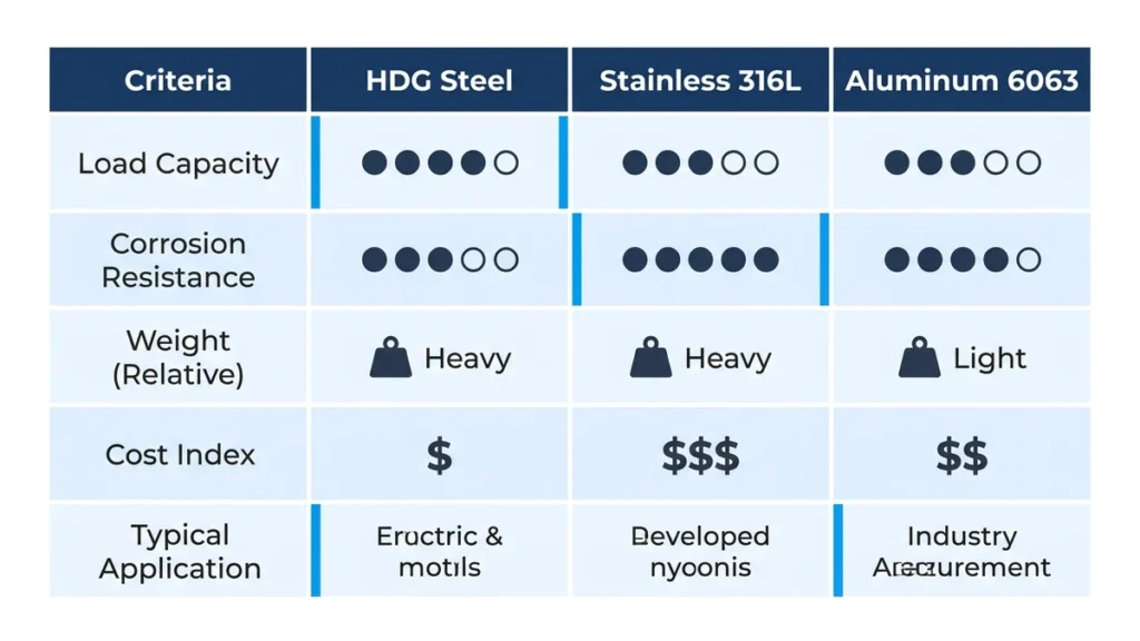
Ladder cable trays are manufactured in three primary materials. Selecting the wrong one for the site environment is one of the most common — and expensive — specification errors in cable management design.
The default choice for industrial plants and outdoor installations. A zinc coating of 45–85 µm per ISO 1461 provides corrosion resistance suitable for sheltered outdoor and moderately aggressive environments. Pre-galvanized (mill-galvanized) steel carries a thinner coating of 10–20 µm and is generally limited to dry indoor applications such as commercial office buildings.
Grade 316 — containing 2–3% molybdenum — is specified wherever chloride concentrations exceed approximately 200 ppm: marine platforms, chemical processing plants, food manufacturing. In a 2023 offshore platform cable management upgrade in the North Sea, Grade 316 ladder trays were selected with a 25-year structural design life, compared to the 7–10 year recoating cycle that galvanized alternatives would have required in that same splash-zone environment.
At roughly 35–40% less mass than equivalent steel trays, aluminum is the preferred choice for overhead routing in long-span configurations where minimizing dead load on building structure matters. Alloy 6063-T5 provides adequate natural corrosion resistance for most indoor and sheltered environments without additional coating. It is widely used in data centers and cleanroom facilities where load-on-structure calculations are tightly controlled.
Selected for chemically aggressive environments — wastewater treatment plants, offshore topsides, explosive atmospheres — where both corrosion immunity and electrical isolation are priorities. FRP trays offer non-magnetic, non-conductive cable routing that neither galvanized nor aluminum can match.
In a 2023 petrochemical plant expansion in Shandong Province covering approximately 14,000 linear meters of cable routing, hot-dip galvanized ladder trays rated at IEC 61537 Class D (200 kg/m) were specified throughout the process area. Post-installation inspection confirmed midspan deflection remained below 12 mm under full design load — within the standard’s L/200 permissible limit for a 3 m span.
[Expert Insight]
– Material selection interacts with grounding strategy: aluminum trays require tinned or stainless bonding jumpers at splice joints to avoid galvanic corrosion where dissimilar metals contact each other.
– In coastal environments classified as Category C5 per ISO 9223, hot-dip galvanized trays typically need inspection within 5 years even with 85 µm coating thickness — stainless or FRP substantially extends maintenance intervals.
– FRP tray weight savings over steel are real, but FRP has lower stiffness; span ratings must be re-evaluated separately from steel equivalents at the same load class.
– Aluminum’s thermal expansion coefficient (~23 µm/m·°C) is roughly double that of steel, requiring expansion joint fittings at intervals no greater than 15 m in high-temperature process areas.
Load capacity is the foundational structural decision in any ladder cable tray specification. Get it wrong and the consequences compound: deflected rails stress cable sheaths at tray edges, ampacity derating calculations become invalid, and future cable additions push the system past its rated limit with no visible warning.
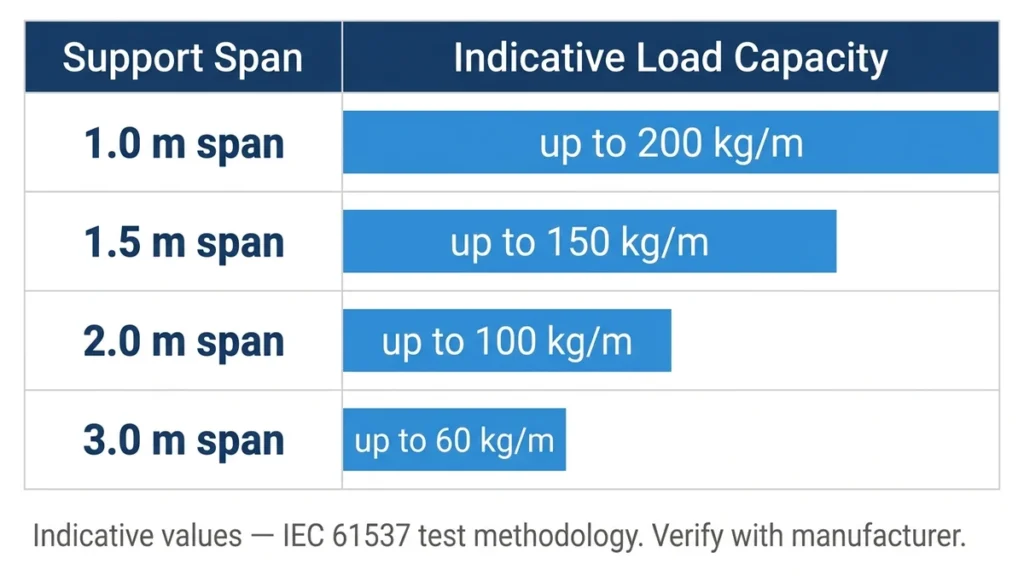
IEC 61537 defines load classes based on the maximum uniformly distributed working load a tray can carry at a reference span of 3 m:
| Load Class | Maximum Working Load | Typical Application |
|---|---|---|
| Class A | 50 kg/m | Light-duty indoor; instrumentation and signal cables |
| Class B | 100 kg/m | General industrial; commercial power distribution |
| Class C | 150 kg/m | Heavy industrial; infrastructure cable runs |
| Class D | 200 kg/m | Utility substations; offshore platforms; cable tunnels |
Each class is verified by a proof load test at 1.7× the working load, with permissible midspan deflection limited to L/200 of the clear span. For a 3 m span, that cap is 15 mm under proof load.
Class selection should account for installed cable fill weight plus a minimum 10% margin for future additions, per IEC 61537 Clause 6.2.
Rail depth is the primary structural variable controlling span capability. A 100 mm deep hot-dip galvanized steel rail at 600 mm tray width spanning 1.5 m can typically carry 150 kg/m within deflection limits. Extend the same tray to a 3 m span without changing rail depth and the safe working load can fall by 40–60%, depending on material grade and rung spacing.
When support spacing exceeds the 3 m reference span — as it commonly does in open industrial bays — permissible uniform load drops in proportion to the square of the span increase. In a petrochemical pipe rack project in Guangdong (2023), increasing support intervals from 3 m to 4.5 m required upgrading from Class C to Class E tray. Material cost rose approximately 22%, but the design eliminated two full rows of intermediate hangers that would have conflicted with pipe rack clearances.
Most manufacturer rating tables assume uniformly distributed cable weight. When junction boxes, cable joints, or pulling eyes are mounted mid-span, the bending moment contribution must be calculated separately. A 60 kg junction box at midspan of a 3 m tray generates a bending moment roughly equivalent to 40 additional kg/m of distributed load — enough to shift a tray from Class B into Class C requirements without any change in cable fill weight.
In a 2023 petrochemical plant expansion in Jiangsu Province covering approximately 4,200 m of cable routing, engineers selected 600 mm wide Class C trays on 3 m spans for 95 mm² power cables alongside control bundles. Post-installation deflection measurements returned midspan values of 11–13 mm under full fill — within the 15 mm IEC 61537 Class C limit — and the design avoided intermediate supports that would have conflicted with pipe crossings.
[Expert Insight]
– Seismic zones add a third load component beyond static cable weight and concentrated fittings: IEC 61537 does not inherently address seismic performance, so projects in Seismic Zone 2 and above typically require supplemental lateral restraint calculations per local structural codes.
– Thermal expansion of galvanized steel trays runs approximately 12 µm/m·°C; across a 30 m run with a 40°C daily temperature swing, that produces nearly 15 mm of movement — enough to shear splice plate bolts if expansion joints are omitted.
– When mixing load classes across a project, engineers should document the class-to-zone mapping clearly in the cable tray layout drawing; field installers using the wrong tray in a higher-load zone is a recurring error on multi-discipline EPC projects.
Three secondary parameters — rung spacing, tray width, and cable fill ratio — determine whether the ladder tray delivers on its thermal and accessibility advantages in daily operation.
Standard rung spacing options are 150 mm, 200 mm, and 300 mm center-to-center. The choice depends on cable outside diameter. For cables under 25 mm OD, 300 mm spacing is generally the maximum acceptable interval before small cables begin to sag between rungs and deform at elevated temperatures. IEC 60364-5-52 provides guidance on cable support intervals relative to cable diameter. For larger power cables — 95 mm² and above — 300 mm rung spacing is standard practice and provides adequate support without constraining bend radius at fittings.
NEC Article 392 limits cable fill to 50% of the tray’s usable cross-sectional area for ladder-type trays carrying single-layer multiconductor cables. Exceeding this fill ratio elevates ampacity derating requirements and creates maintenance access difficulties that directly negate the open-structure advantage ladder tray is designed to provide. Common width options — 150 mm, 300 mm, 450 mm, and 600 mm — should be selected based on projected cable fill at installation plus realistic growth allowance, not just current cable schedule.
Thermal performance confirms the value of maintaining fill ratio discipline. In the 2023 Shandong petrochemical expansion referenced earlier, post-installation thermal surveys confirmed that ampacity derating factors remained at 0.85 or above for grouped power cables — a result that would have required a significantly larger enclosed tray cross-section to replicate.
Correct installation determines whether a ladder cable tray system performs reliably across its 20–30 year service life or becomes a recurring maintenance liability. Field experience consistently points to the same two failure modes: under-spaced supports and inadequate bonding continuity. Both are entirely preventable.
IEC 61537 requires that deflection under proof load not exceed L/200 of the span length. For a 600 mm wide hot-dip galvanized Class C ladder tray, the maximum tray support layout principles is typically 3 m. Exceeding that span without engineering justification produces permanent rail deformation that cannot be corrected without replacing tray sections.
In a 2023 installation review in Shandong Province, post-installation inspection found that 40% of tray runs had been installed at 3.6 m spacing instead of the specified 3.0 m. Under full cable load, measurable rail bow had developed and 18 additional support brackets were required to remediate the affected runs — a corrective cost that significantly exceeded the labor saved during initial installation.
In a separate Jiangsu Province project, the engineering team proactively reduced support spacing from 3 m to 2 m in vibration-prone zones near pump skids. That single adjustment eliminated rail fatigue cracking seen in a prior installation phase and reduced corrective maintenance calls by roughly 60% over the following 18 months.
Ladder cable tray sections used as equipment grounding conductors must maintain electrical continuity across all splice connections. NEMA VE 2 specifies that splice plate bolts be torqued to manufacturer values — typically 20–25 N·m for standard steel hardware — and that bonding jumpers be installed wherever tray sections cross expansion joints or transition between dissimilar metals. Joint resistance should not exceed 0.033 Ω per splice.
Common errors include using painted splice plates without removing the finish at contact points, and omitting bonding jumpers at thermal expansion gaps wider than 6 mm. Both failures interrupt the fault-current return path and can create compliance violations under NEC Article 392.
Power cables rated above 1 kV generally require a minimum bend radius of 12× the cable’s overall outside diameter. Control and instrumentation cables typically require 6–8× diameter. Using undersized radius fittings compresses cable insulation at the inner edge of the bend, accelerating dielectric degradation through thermal cycling over the system’s service life.
Field cuts must be deburred and re-treated with zinc-rich cold galvanizing compound within 24 hours. Hot-dip galvanized trays with untreated cut edges show measurable surface rust within 90 days in outdoor or high-humidity environments, accelerating to section loss in coastal or chemical-exposure zones.
All hardware — rung clamps, splice plates, hanger rods — should match the tray’s corrosion-protection class. Mixing carbon steel hardware with an FRP tray introduces galvanic and mechanical incompatibilities that can void the system’s IEC 61537 corrosion-category rating.
Specifying ladder cable tray correctly requires confirming five parameters before any procurement: load class, material grade, rung spacing, tray width, and surface finish. Each drives a different aspect of long-term system performance, and they interact — a change in span length, for example, cascades into load class, rail depth, and potentially material selection.
Before requesting a quote, confirm: maximum distributed load in kg/m, planned support span in meters, and required tray width in millimeters. A 500 mm wide ladder tray spanning 1.5 m under 75 kg/m behaves very differently from the same tray at 3 m — midspan deflection increases by approximately a factor of four as span doubles, which can push the system outside its rated deflection limit with no change to cable fill weight.
For controlled environments such as data centers or pharmaceutical facilities, aluminum alloy reduces structural dead load while meeting typical cable fill requirements. For industrial and outdoor installations — petrochemical plants, rail yards, utility substations — corrosion category and finish specification per ISO 9223 typically drive the procurement decision more than load class alone. Coastal and chemical-exposure sites should default to Grade 316 stainless or FRP rather than relying on galvanized steel with shortened recoating intervals.
Our full full cable tray system options covers standard load classes, widths from 150 mm to 900 mm, and finish options for both standard and corrosive environments. For projects requiring a complete bill of materials — including routing fittings and transition parts, splice plates, and support hardware — our engineering team can translate a load schedule and routing drawing into a written specification recommendation. For data center applications specifically, understanding the thermal management considerations covered in our industrial and commercial cable tray applications can inform material and configuration decisions before finalizing the specification.
Ladder cable trays are used to route and support power cables, control cables, and instrumentation wiring in industrial plants, commercial buildings, data centers, and infrastructure facilities. Their open structure makes them particularly suitable wherever cable heat dissipation, future modifications, or high cable fill weights are design requirements.
Calculate the total cable weight per meter of tray run using your cable schedule, then add at least 10% for future additions. Match that figure to the IEC 61537 load class table — Class A at 50 kg/m through Class D at 200 kg/m at a 3 m reference span — and verify that your actual support spacing does not exceed the span at which that class was rated.
For cables under 25 mm outside diameter, rung spacing should generally not exceed 150–200 mm center-to-center, as wider spacing allows small cables to sag between supports and risk deformation at elevated operating temperatures. Larger power cables with outside diameters above 40 mm are typically supported adequately at standard 300 mm rung spacing.
Ladder cable tray can serve as an equipment grounding conductor path in many jurisdictions, provided that splice connections maintain continuous electrical continuity — typically no more than 0.033 Ω resistance per splice joint per NEMA VE 2 requirements. Bonding jumpers must be installed at expansion joints and wherever dissimilar metals are joined.
As span increases beyond the IEC 61537 reference span of 3 m, permissible uniform working load decreases approximately in proportion to the square of the span ratio. Doubling the span from 3 m to 6 m does not halve the load rating — it reduces it far more steeply, typically requiring a significant increase in rail depth or load class to maintain compliance.
Under NEC Article 392, single-layer multiconductor cables in a ladder-type tray should not exceed 50% of the tray’s usable cross-sectional area. Staying within this ratio preserves ampacity ratings, reduces thermal grouping effects, and maintains the practical accessibility that makes open-structure ladder tray worth specifying in the first place.
FRP tray is the appropriate choice in environments where both corrosion immunity and electrical isolation are required simultaneously — offshore platforms, chemical processing areas with aggressive vapors, and installations in explosive atmospheres where non-sparking, non-conductive cable support is a safety requirement. In those conditions, neither galvanized steel nor stainless steel provides the combination of properties FRP delivers.
