Address
304 North Cardinal St.
Dorchester Center, MA 02124
Work Hours
Monday to Friday: 7AM - 7PM
Weekend: 10AM - 5PM
Address
304 North Cardinal St.
Dorchester Center, MA 02124
Work Hours
Monday to Friday: 7AM - 7PM
Weekend: 10AM - 5PM
Get premium quality cable management systems directly from the manufacturer.
Fill out the form below to receive our catalog and pricing.
Ladder cable tray applications deliver their strongest performance where cable volume is high, heat dissipation is critical, and long-term accessibility matters. The structural case is straightforward: ladder cable tray is the correct specification when cable bundles exceed 50 mm in total diameter, when ambient temperatures approach 40 °C or above, or when maintenance crews need regular access to individual cables without disturbing an entire run. Understanding which field conditions genuinely favor this structure — rather than defaulting to it — helps engineers specify the right system from the outset rather than retrofitting later.
Ladder cable tray consistently outperforms other cable management systems when cable diameters are large, heat dissipation is critical, or installation spans are long. The open-rung structure addresses three simultaneous engineering demands that enclosed trays cannot: thermal management, structural load capacity, and long-term serviceability. These advantages are precisely why IEC 61537-compliant cable tray systems remain the first specification choice in heavy industrial and infrastructure projects globally.
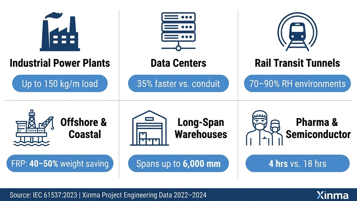
Power plants, petrochemical refineries, and steel mills generate some of the highest cable load densities in any built environment. Ladder cable tray handles distributed loads up to 150 kg/m across 3 m spans — a condition where solid-bottom trays require significantly heavier gauge steel and more frequent support brackets. The open rung design, with typical rung spacing of 150–300 mm, allows natural convection cooling for power cables carrying high amperage, directly reducing the ampacity derating factor required under IEC 60364-5-52.
In a 2023 petrochemical expansion project in Shandong Province covering approximately 12 km of cable routing, switching from solid-bottom tray to ladder cable tray in high-voltage cable runs reduced the required conductor cross-section by one size class, saving an estimated ¥2.3 million in copper costs. That single procurement decision paid for the specification review several times over. For projects combining power and instrumentation runs, a perforated cable tray alongside dedicated ladder tray routes is a common split that reduces total material cost by 12–18% without compromising load compliance.
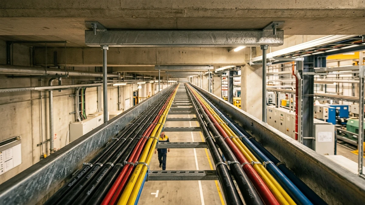
Overhead cable routing in hyperscale data centers demands both high fill capacity and thermal transparency. Ladder cable tray — particularly in widths of 450–600 mm — accommodates dense bundles of power and signal cables while preserving the airflow paths that overhead and underfloor cooling systems depend on. Data centers above 5 MW IT load routinely specify ladder cable tray for overhead power distribution precisely because the open structure permits natural convection cooling along the cable jacket.
Unlike wire mesh tray, ladder tray provides the structural rigidity needed for spans exceeding 1.5 m without mid-span supports — a practical advantage in raised-floor environments where support column placement is constrained by server rack geometry. Per IEC 60364-5-52 wiring method ampacity correction tables [VERIFY STANDARD], grouping factors improve measurably when airflow is unrestricted on three sides of the cable bundle.
Underground utility corridors present conditions where moisture resistance, load capacity, and maintenance access all converge simultaneously. Hot-dip galvanized ladder cable tray rated to a coating thickness of ≥ 85 µm withstands the high-humidity, condensation-prone environments typical of urban utility tunnels. The open ladder structure also allows cable inspection and replacement without disturbing adjacent bundles.
Beijing’s municipal utility tunnel program (2021–2024) quantified this directly: ladder tray sections reduced average cable replacement time by approximately 40 minutes per 10 m segment compared to enclosed conduit routes. Over a large network, that time saving compounds into significant operational budget reductions.
On rooftops, along exterior building facades, and between industrial structures, ladder cable tray handles wind loading and thermal cycling that would deform lighter cable management systems. Stainless steel or heavily galvanized carbon steel versions maintain structural integrity across temperature ranges from –40 °C to +80 °C, making them suitable for outdoor process plant cable bridges where ambient conditions vary seasonally. The open structure also prevents water ponding that accelerates corrosion on tray floors and cable jackets alike. Cable systems exposed to vibration or seismic loads benefit further from matching tray selections with compatible seismic bracing systems to restrain lateral movement under dynamic loads.
[Expert Insight]
– Ampacity derating is not a theoretical concern — field measurements at a 2023 industrial project in Zhejiang Province confirmed a 14 °C average conductor temperature reduction when switching from enclosed wireway to open ladder tray across a 480 m route at full load.
– IEC 60364-5-52 grouping correction factors can drop to 0.60 for cables bunched in enclosed trays without airflow; ladder tray’s open rung design routinely recovers 15–25% of that lost capacity in practice.
– Engineers who specify ladder tray for thermal reasons should document the rung pitch used — 150 mm and 300 mm center-to-center produce different airflow profiles, particularly in stacked multi-layer cable arrangements.
– Fiber optic and instrumentation cables co-routed with power circuits benefit from physical dividers on the rung surface rather than separate tray runs, provided the power cable temperature rise is characterized at design stage.
The load and span requirements of heavy infrastructure are where the ladder cable tray’s structural design becomes non-negotiable rather than merely preferred.
In petroleum refineries, petrochemical plants, and cement processing facilities, ambient temperatures routinely exceed 60 °C near process equipment. Cable bundles carrying power circuits to motor control centers generate additional self-heating on top of that ambient load. The open-rung geometry — rung spacings of 150 mm to 300 mm — allows free air circulation along the full cable bundle length, reducing the ampacity derating factor that would otherwise apply under IEC 60364-5-52 for cables in enclosed conduit or solid-bottom tray.
Without adequate ventilation, engineers must apply a derating factor as low as 0.60 for cables bunched in enclosed trays, meaning a cable rated at 100 A in free air may only carry 60 A safely. In a 2024 expansion project at a cement clinker facility in Shandong Province (covering approximately 4,200 m of cable routing), switching from solid-bottom trays to ladder trays in kiln-adjacent areas eliminated the need for oversized cable cross-sections, reducing copper material costs by approximately 22% while keeping conductor temperatures within the 90 °C XLPE insulation threshold.
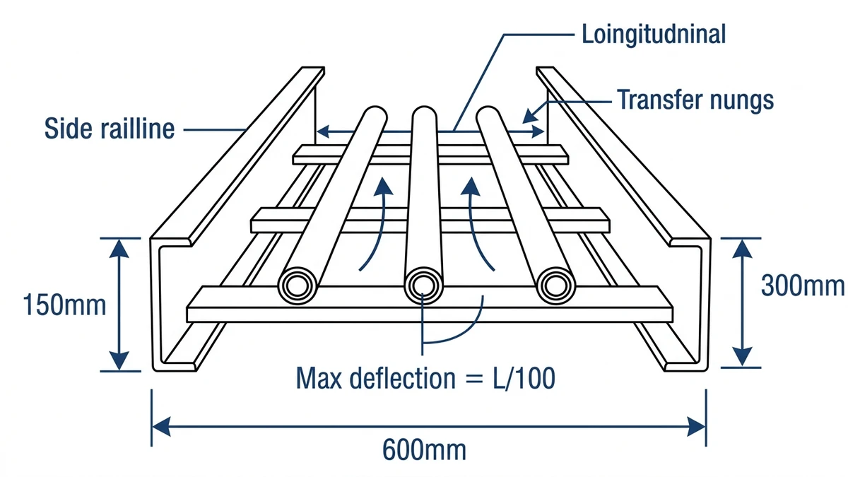
Power plants, steel mills, and large warehouse distribution centers frequently require cable runs spanning 3 m to 6 m between supports — spans that are structurally impractical with lighter cable management systems. Ladder trays with steel side rails and welded rungs achieve load class ratings up to 200 kg/m under IEC 61537, the standard governing cable tray and cable ladder systems for deflection limits, load classification, and corrosion protection.
At a 6 m span, a hot-dip galvanized steel ladder tray 600 mm wide typically supports 90–120 kg/m while maintaining midspan deflection within the IEC 61537 Class C limit of L/200 (30 mm maximum). Solid-bottom or perforated trays of equivalent steel gauge deflect significantly more under identical distributed loads because their rail geometry cannot match the ladder system’s effective section modulus. For power distribution runs exceeding 30 m with cable loads above 40 kg/m, the ladder tray’s longitudinal rigidity becomes structurally decisive — side rails fabricated from 2.0 mm or 2.5 mm cold-rolled steel provide the bending moment resistance needed to stay within those deflection limits.
In metro tunnel projects and highway tunnel electrical fitouts, ladder cable tray installed on sidewall brackets provides the open structure required by fire safety codes — debris and water drain freely, and cable inspection does not require tray removal. The mechanical robustness of the ladder form also accommodates seismic restraint hardware directly onto side rails without secondary framing, a practical advantage in seismic zones classified under ASCE 7-22 or GB 50981.
The Chengdu Metro Line 8 civil works (2023) selected stainless steel ladder tray rated at 150 kg/m for underground signal and traction power cable runs precisely because the open structure simplified post-installation cable identification during commissioning — a quiet operational benefit that becomes significant when hundreds of circuits require verification under schedule pressure.
[Expert Insight]
– IEC 61537 classifies cable tray load capacity from Class A (50 kg/m) through Class D (200 kg/m); specifying one class higher than calculated fill weight is standard practice for installations where future cable additions are likely.
– Long-span ladder trays in seismic zones should have seismic restraint clips verified against the applicable zone classification before procurement — the side rail profile determines which clip styles are compatible.
– In tunnel environments, stainless steel (Grade 316L) is preferred over hot-dip galvanized steel where condensation is persistent; the initial cost premium of approximately 35–50% over galvanized is typically recovered within the first major maintenance cycle.
– For mixed power and instrumentation cable routing, physical dividers on the rung surface outperform color-coded cable ties as a segregation method under IEC 60364-5-52 separation requirements.
Three field conditions consistently push ladder cable tray from a preferred option to the only practical one: high-heat industrial zones, chemically aggressive environments, and installations where large-diameter cables demand both clearance and ventilation simultaneously.
In petrochemical facilities, water treatment plants, and coastal installations, cable management must drain continuously and resist chemical attack. Ladder trays fabricated from 316L stainless steel or fiberglass-reinforced polymer (FRP) handle pH ranges from 2 to 12 without coating degradation — a performance band that hot-dip galvanized carbon steel cannot reliably sustain in chlorinated or acid-mist environments. The open rung spacing, typically 150 mm to 300 mm on center, allows standing water and process splashback to drain immediately, eliminating the pooling that corrodes solid-bottom tray floors over 3–5 year service cycles.
A 2023 expansion project at a coastal desalination plant in Oman demonstrated this directly: FRP ladder cable tray reduced maintenance intervention from quarterly cleaning cycles to annual inspection, cutting cable infrastructure labor costs by approximately 42% over the first 18 months of operation. For offshore oil platforms in the North Sea, GRP ladder trays rated for continuous salt-spray exposure at wind loads up to 1.5 kN/m² are standard specification — equivalent steel systems require biannual recoating cycles to maintain integrity. Full accessory compatibility for these environments is covered in the cable tray accessories range, including corrosion-resistant fittings and sealing components.
Hot-dip galvanized ladder tray applied at 85 µm average zinc thickness provides service life exceeding 25 years in C3 corrosivity class environments per ISO 9223 classification.
Power cables above 50 mm outer diameter cannot be routed through standard conduit without severe bending radius violations. Ladder cable tray accommodates these cables on the tray floor with compliant bend radii — typically ≥ 8× cable outer diameter for armored cables — and its open structure allows a single tray run to carry segregated groups of power, instrumentation, and fiber cables, separated by physical dividers or stagger routing on different rung levels.
In a 2024 combined-cycle power plant project in Guangdong Province (600 MW capacity), engineers routing 185 mm² MV feeder cables across a 120 m cable bridge switched from solid-bottom tray to ladder tray midway through procurement. The change reduced ampacity derating losses and allowed a 15% reduction in conductor cross-section for secondary runs, cutting copper costs by approximately ¥340,000 on that segment alone. This mixed-use cable routing capability also reduces total support steel requirements compared to running parallel dedicated conduit banks.
In areas classified under IEC 60079-14 for explosive atmospheres, ladder cable tray supports intrinsically safe and Ex-d cable routing without the conduit seal fittings that rigid conduit systems require. The unrestricted airflow prevents localized heat accumulation that could elevate cable surface temperatures above the T-class rating of installed equipment — a failure mode that enclosed systems cannot self-correct under sustained high-load conditions.
Selecting the right ladder cable tray configuration — correct width, load class, rung spacing, and surface finish — directly affects installation time, long-term reliability, and code compliance. Even small mismatches, such as choosing a 75 mm rung pitch where 300 mm spacing would suffice, can add unnecessary material cost or compromise cable bend radius in high-density runs.
Our technical team works with project engineers, EPC contractors, and facility managers on applications ranging from 11 kV substation cable risers to industrial plant cable routing systems spanning up to 6 m between supports. Specification support covers:
To get useful answers quickly, share cable types and maximum cable OD, estimated fill weight per meter, ambient temperature range, any chemical or humidity exposure, span lengths and support intervals, and applicable standards (NEMA VE 1, IEC 61537, or local authority requirements).
In a 2024 petrochemical expansion project in Shandong Province, a specification review conducted before procurement identified an undersized load class selection that would have required re-installation of approximately 420 m of tray — a correction that saved an estimated six weeks of rework. Precise input at the specification stage prevents that kind of downstream cost. Reach out with your project details for application-specific guidance within one business day.
For engineers specifying systems for high-temperature industrial cable routing, evaluating corrosion-resistant tray materials for offshore applications, or reviewing IEC 61537 load class options for long-span installations, the configuration decisions made at this stage determine both compliance and total installed cost.
Ladder cable tray is typically the appropriate choice when cable bundles exceed 50 mm in total diameter, when ambient temperatures approach or exceed 40 °C, or when support spans exceed 2 m — conditions where solid-bottom tray requires heavier gauge steel and more frequent supports to stay within deflection limits.
The open rung design maintains natural convective airflow around cable jackets, which directly improves the grouping correction factors applied under IEC 60364-5-52; cables in enclosed trays without airflow can require derating to as low as 0.60 of their free-air rating, whereas well-ventilated ladder tray installations may recover a significant portion of that lost capacity.
Rung spacings of 150–200 mm are generally appropriate for lighter signal and instrumentation cables where bend radius is a concern, while 300 mm spacing is common for heavy power cables; the minimum bending radius of the largest cable in the bundle — typically ≥ 8× cable outer diameter for armored cables — should govern the final selection.
Hot-dip galvanized steel at ≥ 85 µm zinc thickness suits C3 corrosivity class environments with moderate humidity; 316L stainless steel is preferred where persistent condensation or chloride exposure is present; FRP ladder tray is typically specified for pH ranges of 2–12 or acid-mist areas where metallic systems show accelerated degradation within 5–7 years of service.
Standard ladder cable trays commonly span 3 m between support brackets, with heavy-duty fabricated rail designs reaching up to 6 m under IEC 61537 Class D loading at 200 kg/m; the allowable span depends on tray width, rail gauge, cable fill weight, and the L/200 midspan deflection limit specified in IEC 61537.
Ladder cable tray can be used to route Ex-d and intrinsically safe cables in Zone 1 classified areas, provided the installation complies with IEC 60079-14 requirements for cable separation, support, and surface temperature management; the open structure’s continuous airflow helps prevent localized heat buildup that could elevate cable surface temperatures above equipment T-class ratings.
Tray width selection is generally based on a 40% maximum cable fill ratio for initial installation, which leaves capacity for future cable additions; the total cross-sectional area of planned cables (accounting for cable OD and any required segregation dividers) is divided by the tray’s usable internal width, and a standard commercial width — typically 150 mm to 600 mm — is selected to satisfy that fill ratio while meeting the bend radius requirements of the largest cable in the run.
