Indoor vs outdoor cable tray systems differ because the design basis changes. Indoors, trays are usually selected around cable weight, fill, access, and fire behavior. Outdoors, the same tray must also resist UV, rain, wind uplift, corrosion, and wider temperature swings—often reducing support spans from about 3.0 m indoors to roughly 2.0–2.5 m outdoors once covers and environmental loads are included.
For specifiers, that means “same tray, different location” is rarely a neutral choice. A system that works in a dry electrical room may need different material, splice treatment, cover retention, and thermal allowance on a roof, pipe rack, or coastal structure. IEC 61537 and NEMA VE 1 provide the framework for load behavior, deflection, and environmental suitability, but project conditions decide which checks govern.
If you are comparing tray options broadly, Xinma’s overview of cable tray systems is a useful starting point. This article focuses on what changes in engineering terms when a tray route moves from indoor service to outdoor exposure.
Indoor vs Outdoor Cable Tray Design: A Side-by-Side Engineering Comparison
The short answer is this: indoor cable tray design is usually governed by gravity load and access, while outdoor design becomes a combined structural, corrosion, and thermal problem. The tray may look similar on the drawing, but the governing failure modes are different.
Parameter-by-parameter comparison
Design parameter
Indoor cable tray system
Outdoor cable tray system
Engineering consequence
Ambient temperature
Typically 20–35 °C
Commonly -20 °C to 45 °C ambient, with sunlit metal surfaces running higher
Outdoor cable tray runs need more thermal margin and closer ampacity review
Corrosion exposure
Usually low in conditioned spaces
Rain, salt, condensate, washdown, and industrial fallout are common
Material selection often shifts before tray width does
Cover requirement
Optional in many spaces
Frequently used for UV, debris, weather, or impact shielding
Covers improve protection but add mass and may trap heat
Structural loads
Cable dead load dominates
Dead load plus uplift, thermal movement, and sometimes snow/debris retention
Support spacing and hold-down details often change
Support span
Often 1.5–3.0 m depending on tray type and load class
Commonly shortened when covers or higher exposure are present
Outdoor systems may need more supports for the same cable fill
Drainage
Usually not a primary issue
Water retention and contamination matter
Drain paths and low-point detailing become design items
Maintenance access
Fast access often preferred
Access may be slower due to covers and weather hardware
Protection improves; intervention time usually increases
What changes first in real design reviews
In most reviews, tray width is not the first thing that changes; material and support detailing are. A ladder tray carrying 40 kg/m over a 3.0 m indoor span may be acceptable in standard galvanized steel, but the same run outdoors with a cover and moisture exposure may need hot-dip galvanized steel or aluminum plus shorter supports around 2.0–2.4 m.
Thermal treatment is the next common change. Open tray performance indoors is usually predictable, while a dark covered tray in sun can raise cable temperature above ambient and reduce ampacity margin. When heat rejection is critical, open or ventilated tray is usually preferred; covers should be used only when UV, contamination, or impact risk justifies the penalty.
Designers often compare tray form first, but the support and exposure conditions matter just as much. Xinma’s page on ladder cable tray configurations is useful when drainage and ventilation drive the decision.
[Expert Insight]
On exposed roof runs, the cover often changes the support schedule more than the cable load.
Outdoor covered sections usually stay cleaner, but each inspection takes longer.
Where only part of a run is outdoors, the transition section often needs the most attention.
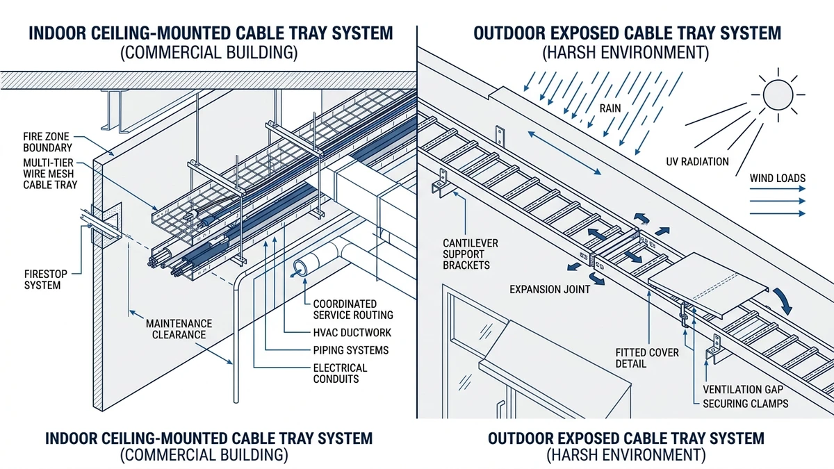
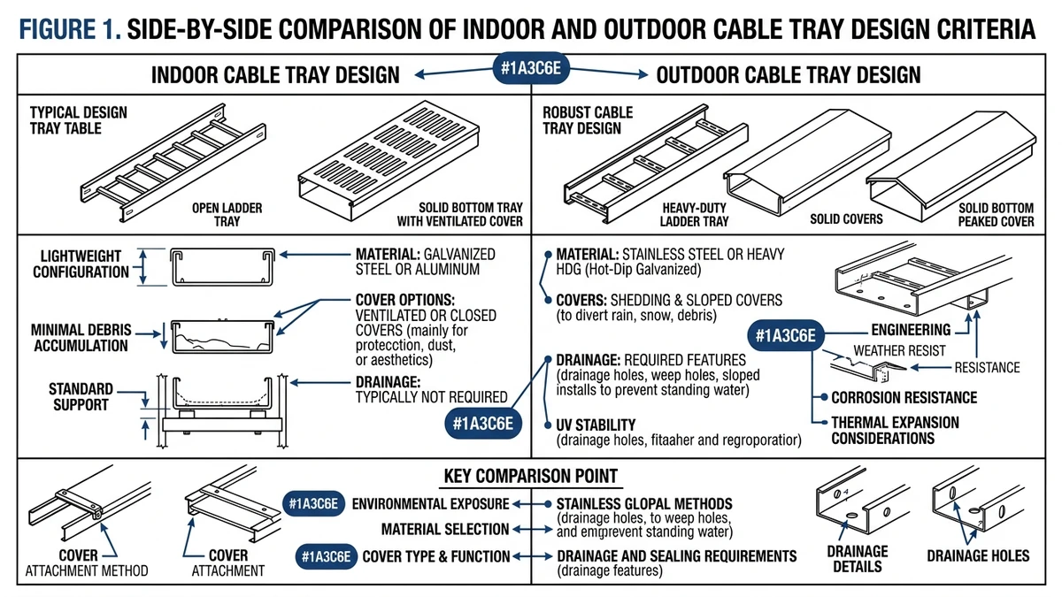
Figure 1. Side-by-side comparison of indoor and outdoor cable tray design criteria, including exposure, materials, covers, drainage, and maintenance implications.
Structural and Environmental Loads: What Outdoor Cable Tray Design Adds
Outdoor cable tray design adds loads many indoor runs do not see continuously: wind, uplift on covers, rainwater retention, corrosion cycling, and larger thermal movement. At that point, the comparison becomes an engineering check, not a feature list.
Load mechanism, range, and design consequence
For indoor runs, the governing load is commonly a uniform cable load of about 40–75 kg/m over a 2.0–3.0 m span, with tray load class and deflection as the main checks. Outdoors, the same cable weight may no longer govern because a cover increases projected area and uplift demand, changing bracket, clamp, and splice requirements.
Temperature movement also becomes significant. Steel expands by about 12 × 10⁻⁶/°C, so a 30 m run with a 50 °C swing moves about 18 mm. That is enough to justify expansion splice plates, sliding supports, or movement allowance at selected joints.
Why outdoor support spacing usually gets shorter
The usual mistake is assuming the answer is simply a stronger tray. In practice, shorter support spacing is often the cleaner solution because it controls deflection, cover vibration, and fitting stress at the same time.
A tray acceptable indoors at 3.0 m may need to reduce to 2.0–2.5 m outdoors once cover weight, environmental loading, and retention hardware are included. This is about serviceability as much as strength, because longer spans can increase rattle, fastener loosening, and stress at bends and tees.
IEC 61537 covers cable tray and cable ladder systems, including load and deflection testing, while NEMA VE 1 gives construction and performance guidance for metal cable trays. For standards context, see IEC 61537: IEC 61537 publication page.
Use when / avoid when / check before specifying
Use indoor load assumptions when
The run is fully sheltered, temperature variation is modest, and there is no meaningful exposure to wind-driven dust or water.
Avoid indoor assumptions when
The tray crosses roofs, open racks, coastal structures, or partially enclosed areas with changing moisture and airflow. Even a short exposed section can govern the design.
Check before specifying
Confirm support spacing, uplift restraint, expansion allowance, and corrosion exposure together. In mixed indoor/outdoor runs, the first service issues usually appear at fittings and transitions, not straight sections.
[Expert Insight]
Fittings often become the critical outdoor points because uplift, vibration, and water entry concentrate there.
If removable covers are specified, leave practical removal clearance—typically around 300 mm above tray.
“Outdoor” is not one condition; a canopy route and an open rooftop route may need different hold-down and corrosion strategies.
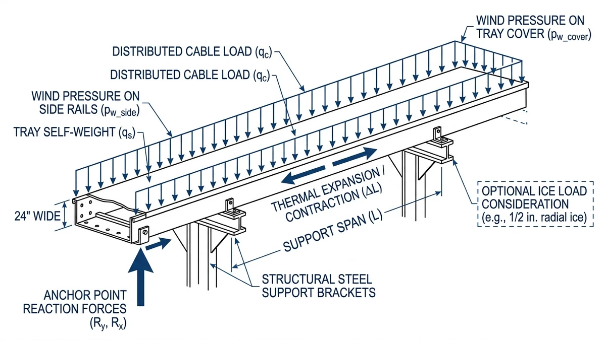
Figure 2. Outdoor cable tray design must account for cable load, self-weight, wind action, thermal movement, and support reactions across exposed spans.
Material, Drainage, and Cover Strategy: How Tray Type Selection Changes by Environment
Material choice, drainage, and cover strategy are linked. Improving one usually affects the others.
Material selection is driven by degradation mechanism
Indoors, pre-galvanized steel or aluminum is often adequate in controlled spaces with low chemical exposure. Outdoors, selection commonly shifts to hot-dip galvanized steel, aluminum, or stainless steel 304/316 when salt, condensate, or washdown can shorten coating life.
The key engineering point is that corrosion starts at cut edges, fastener interfaces, and standing-water locations before the tray looks badly damaged. In many projects, corrosion class governs material choice before structural load class does.
For projects comparing options by environment, Xinma’s guide to perforated tray layouts is useful where drainage and partial enclosure must be balanced.
Drainage and contamination are a trade-off, not a checklist
Decision area
Favor indoor approach
Favor outdoor approach
Resulting trade-off
Base material
Lower-corrosion finishes in controlled interiors
Hot-dip galvanized, aluminum, or stainless in exposed zones
Higher durability outdoors, higher upfront material cost
Drainage
Often secondary
Critical on long horizontal runs
Better water management may mean less enclosure
Cover strategy
Optional or partial
Often used for UV, debris, or impact protection
Better shielding, less ventilation
Ventilation
Usually easy to maintain
Can be restricted by covers and solar gain
Thermal review becomes more important
Access
Fast intervention preferred
Protection may outweigh speed
Maintenance frequency drops; intervention time rises
A ladder tray or ventilated perforated tray often suits outdoor routes where heat rejection and drainage matter most. A solid-bottom tray with a cover suits routes where contamination control matters more than ventilation.
One strong example shows the trade-off: adding a steel cover over a 2.0 m section can add several kilograms of distributed load, enough to reduce allowable cable load or force closer supports on a 3.0 m span. At the same time, that cover can materially reduce debris accumulation and UV exposure.
Use when / avoid when / check before specifying
Use covered tray when
The route is exposed to falling debris, UV, rain splash, or contamination severe enough to affect cable reliability.
Avoid full covers when
Heat dissipation is already tight, cable fill is high, ambient exceeds about 35 °C, or maintenance access is frequent.
Check before specifying
Review ampacity derating, support span, clamp retention, drainage at low points, and water behavior at bends, tees, and reducers. Fittings are usually where trapped debris and standing water appear first.
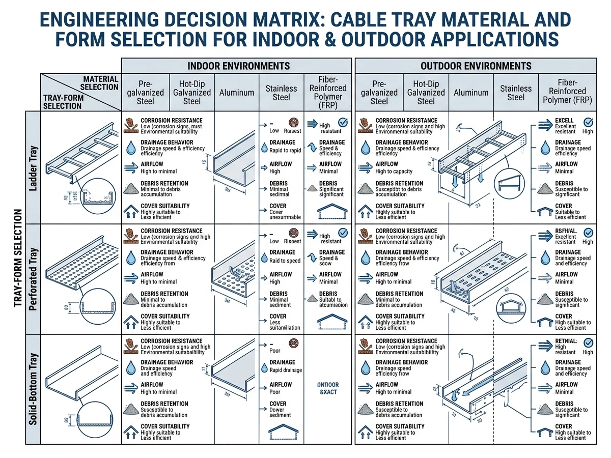
Figure 3. Decision matrix comparing tray materials, tray forms, drainage behavior, and cover strategy for indoor and outdoor cable management conditions.
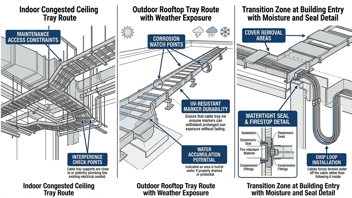
What Changes in Real Installations: Maintenance, Access, and Transition Zones
Straight runs get most of the drawing space. Transition zones create many of the actual problems.
Maintenance reality: open reach versus protected reach
Indoor tray layouts usually favor fast inspection and modification. In clean electrical rooms, technicians can inspect cable condition, check fill, and add circuits without removing extra hardware.
Outdoor runs change that balance. Covers, hold-down clips, weather seals, and bonding details improve protection but add time to each intervention. In similar industrial routes, a covered outdoor access point commonly adds about 5–10 minutes for opening, inspection, and re-closing.
Transition zones are where many service issues start
The indoor-to-outdoor transition is often the highest-risk detail because temperature, moisture, support condition, and sealing requirements change together. A tray leaving an air-conditioned building may see a 20–40 °C local shift, introducing condensation risk, movement, and hardware loosening.
If that same route crosses a fire-rated wall or roof penetration, support, bend radius, seal detail, and movement allowance must be coordinated. If they are not, jacket wear or water ingress often appears at the entry point first.
IEC 61537 applies to the installed system, not just the straight tray. In practice, reducers, bends, tees, and splice interfaces are where deflection, corrosion, and abrasion become visible earliest.
Practical checklist for transition design
Use indoor-style access when
Cable additions or terminations are expected more than about 2–4 times per year, the space is dry, and visual inspection is routine.
Use outdoor-style protection when
The route is exposed to rain, dust, UV, washdown, or falling debris, and inspection intervals are longer—often 6–12 months.
Check before specifying
Support spacing before and after the wall or roof crossing
Expansion allowance and splice selection
Drainage path to prevent trapped water
Seal and firestop compatibility with cable movement
Clearance for cover removal, typically about 300 mm above tray
Edge protection where cables enter enclosed sections
If sizing is still being finalized, Xinma’s article on cable tray size calculation methods can help connect cable fill assumptions to support and access decisions, especially where the route changes environment mid-run.
Figure 4. Transition zones between indoor and outdoor tray routes often combine moisture exposure, access limits, and maintenance complexity in one location.
How Xinma Helps Coordinate Loading, Corrosion, Covers, and Fittings Decisions
Indoor vs outdoor cable tray systems should not be specified by tray profile alone. Once the route moves outdoors, corrosion exposure, cover mass, uplift, drainage, and fitting restraint start interacting, so the engineering task becomes system coordination.
A few consequences usually drive the review:
Adding a cover can increase dead load by several kg/m, which may reduce support spacing from about 3.0 m to 2.0–2.5 m depending on tray width, load class, and allowable deflection.
Corrosion exposure may shift the finish from pre-galvanized steel to hot-dip galvanized steel, aluminum, or stainless steel where salt, condensate, or washdown shortens coating life.
Horizontal bends, risers, and tees outdoors often need stronger hold-down and splice detailing because uplift and vibration concentrate at fittings.
Solid covers can improve UV and debris protection but may increase cable temperature, so ventilation and ampacity need to be reviewed together.
Xinma supports that coordination by reviewing tray width, side rail depth, cover type, fitting compatibility, and support spacing against stated cable load in kg/m and site exposure. This is particularly useful when one route includes indoor open sections and outdoor covered sections using different hardware and finishes.
For projects moving toward procurement, the most useful next step is usually to align the fittings schedule and support logic with the tray selection itself. Xinma’s resources on cable tray fittings and connection details and on installation support requirements are relevant here because many specification gaps appear between straight sections and real-world support conditions.
A practical final check: if the route requires weather-resistant fasteners, hold-down clamps, expansion treatment, or corrosion-resistant accessories, the design should be reviewed as an outdoor cable tray condition even if only part of the run is exposed.
Frequently Asked Questions
What is the main difference between indoor and outdoor cable tray systems?
Indoor systems are usually selected around cable load, access, and fire-related considerations, while outdoor systems must also account for corrosion, weather exposure, thermal movement, and cover retention.
Do outdoor cable tray systems always need covers?
Not necessarily. Covers are useful when UV, debris, falling objects, or rain exposure create a real reliability issue, but they can also increase heat buildup, dead load, and maintenance time.
How much can support spacing change when a tray run moves outdoors?
It often changes by project condition, but a span acceptable at about 3.0 m indoors may need to reduce to roughly 2.0–2.5 m outdoors once cover weight and environmental actions are checked.
Which tray type is usually better outdoors: ladder or solid-bottom?
Ladder tray often suits outdoor runs where drainage and heat dissipation are the priority, while solid-bottom arrangements are more appropriate when contamination shielding matters more than ventilation.
Why do transition zones between indoor and outdoor sections fail more often?
Those locations combine movement, moisture change, support discontinuity, and sealing requirements in a short distance, so small detailing gaps tend to show up there first.
How should I validate an outdoor tray specification before procurement?
Check the tray as an installed system: material finish, support spacing, cover retention, fitting restraint, drainage path, and thermal allowance should all align with the site exposure and cable load.
Kevin Zheng
Kevin Zheng is a manager linked to Shanghai Xinma Busway & Cable Tray Co., Ltd. He writes technical content on cable tray systems, installation practice, sizing logic, load classes, and related standards for industrial and infrastructure applications.