What Is FRP and Fiberglass Cable Tray, and Where Do Non-Metallic Systems Make Sense?
FRP and fiberglass cable tray is a non-metallic cable management system made from glass-fiber-reinforced resin. It is most useful where corrosion, washdown, salt exposure, or chemically aggressive atmospheres shorten the life of metal trays. Under IEC 61537, core checks still include load, deflection, and impact, but in practice the environment usually drives the decision first.
FRP is not a universal replacement for steel or aluminum. It is commonly used in coastal plants, wastewater facilities, desalination sites, fertilizer units, and chemical process areas where coating breakdown, galvanic attack, or repeated wet cleaning make metallic trays harder to maintain. Typical support spans are about 1.5-3.0 m, with practical ambient exposure often around 40-60 °C depending on resin, UV resistance, and fire requirements.
Treating FRP as “corrosion-proof steel” leads to poor layouts. The better approach is to treat it as a different tray system with different strengths, limits, and detailing needs.
For a broader overview of system types and use cases, Xinma’s guide to where cable tray systems are applied gives useful context before narrowing down to non-metallic options.
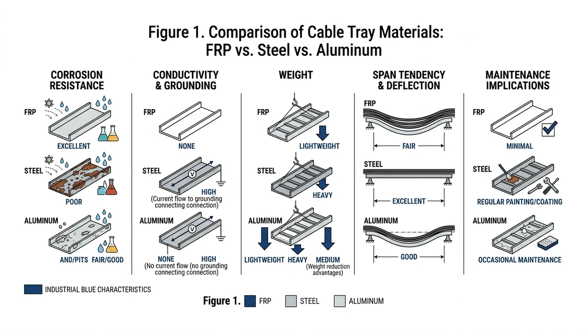
How FRP Cable Tray Differs from Steel and Aluminum in Real Service Conditions
FRP cable tray differs from steel and aluminum in ways that change support spacing, grounding, thermal detailing, and maintenance. The right choice depends on the dominant failure mode in the real service environment.
Engineering comparison by service condition
Service parameter
FRP cable tray
Steel cable tray
Aluminum cable tray
Design consequence
Corrosion resistance
High in coastal, wastewater, and many chemical atmospheres; resin chemistry matters
Good initially, but coating damage can create corrosion sites
Good in many atmospheres, but some chloride-heavy or alkaline exposures are problematic
Favor FRP where corrosion is the life-limiting factor
Electrical conductivity
Non-conductive
Conductive
Conductive
FRP does not provide bonding continuity or fault-current return path
Weight
Typically 25-35% of comparable steel tray weight
Heaviest
About 35-50% lighter than steel
Lower dead load can reduce support steel and ease installation
Stiffness
Lower modulus
Highest stiffness
Intermediate
FRP usually needs shorter spans or deeper sections to control deflection
Thermal expansion
Higher, often about 1.8-2.4× steel
Lower
Higher than steel, generally below FRP
Long outdoor runs need more deliberate expansion detailing
Heat tolerance
Resin-dependent continuous service limit
Good at elevated temperature
Strength reduces as temperature rises
Check actual tray rating at process-area ambient temperatures
Fire behavior
Depends on resin and additives
Non-combustible base metal
Non-combustible base metal
Review carefully in tunnels, escape routes, and petrochemical fire zones
EMC behavior
Non-conductive, non-magnetic
Conductive; can support bonding/shielding strategy
Conductive, non-magnetic
Metal often remains the simpler choice for EMC-sensitive routing
Maintenance profile
No recoating, but inspect for UV aging, cracks, and impact damage
Inspect coating loss, rust, and bonding continuity
Inspect joints, galvanic interfaces, deformation
FRP reduces corrosion maintenance, not mechanical inspection
A useful example is a 300 mm tray carrying 40 kg/m over a 3.0 m span. That may be routine in steel, but FRP may become deflection-controlled before strength-controlled, requiring a deeper rail or shorter span.
What changes in real project decisions
In outdoor process and wastewater routes, metallic deterioration often starts at cut edges, joints, and supports. FRP reduces that corrosion burden, but the design focus shifts to support spacing, fitting stiffness, and thermal movement.
Grounding also changes. Metal tray may contribute to bonding continuity if approved; FRP cannot, so a separate protective conductor is usually needed.
Figure 1. FRP cable tray is compared with steel and aluminum by corrosion resistance, conductivity, weight, span tendency, and maintenance implications.
[Expert Insight]
If the route is chemically severe but electrically simple, FRP often reduces life-cycle maintenance even when initial support count increases.
If the route depends on tray continuity for bonding or shield management, metal generally stays easier to coordinate.
For outdoor runs above 20-30 m, expansion details should be reviewed early; they are harder to retrofit than extra supports.
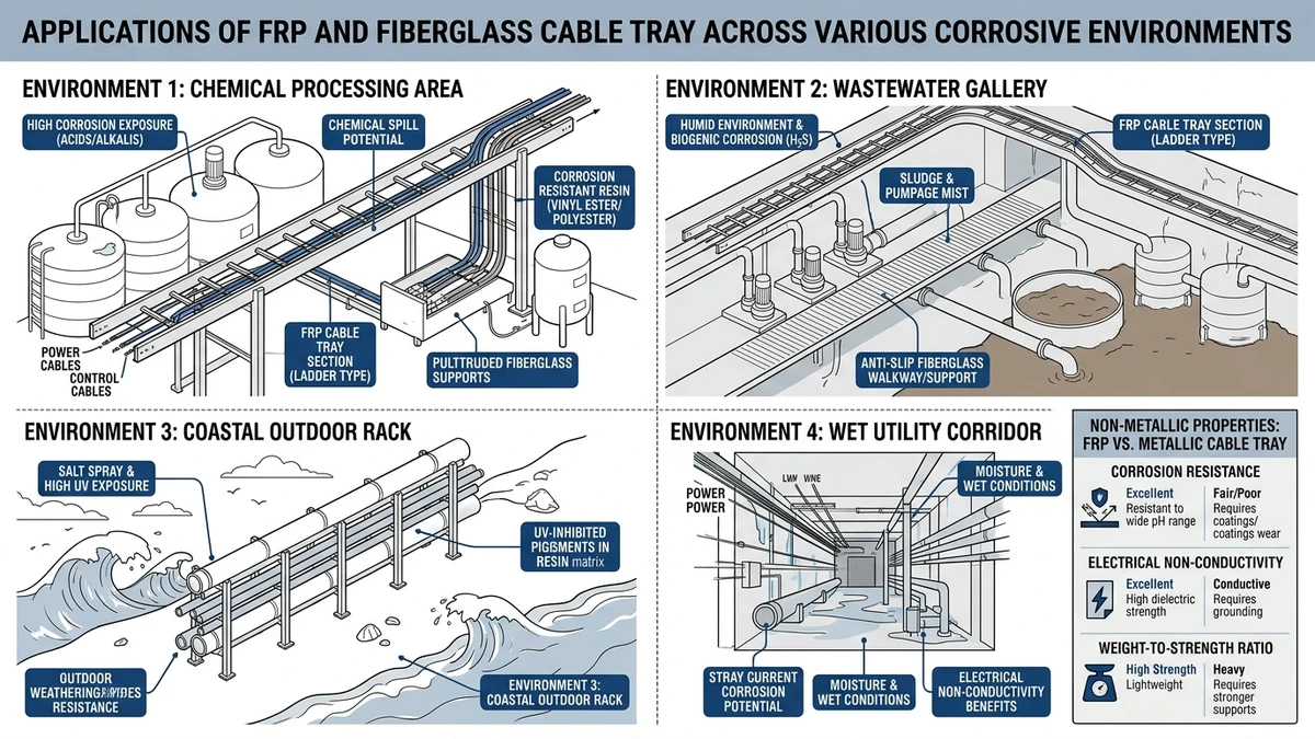
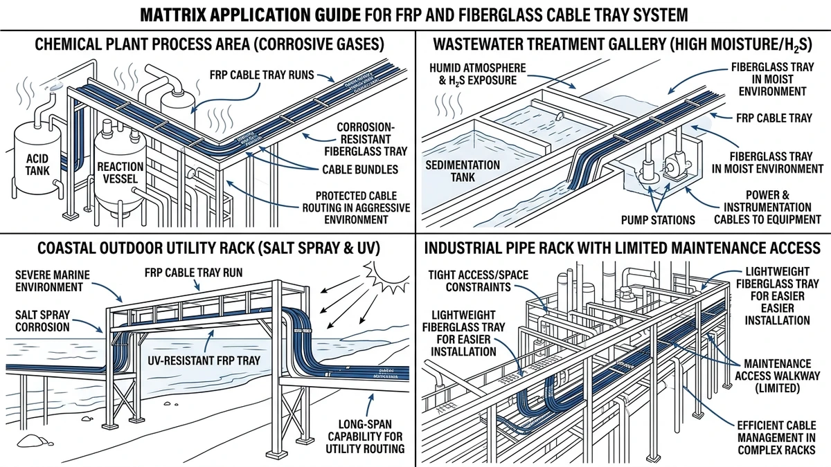
Where FRP and Fiberglass Cable Tray Usually Performs Best
FRP and fiberglass cable tray performs best where environmental attack, not maximum structural efficiency, is the main design problem. Typical drivers are corrosion, washdown, UV exposure, salt moisture, or the need to avoid unintended conductive paths.
Application matrix by field environment
Environment
Why FRP fits
Design consequence
Main limitation to check
Coastal and marine atmospheres
Salt moisture accelerates corrosion on metallic finishes
Fewer corrosion-driven replacements on exposed runs
UV resistance and hardware material still matter
Chemical plants and wastewater treatment
Acids, alkalis, chlorine compounds, and washdown attack metallic coatings
Select resin by exposure zone, not by generic material label
Some solvents and hot chemicals may require specific resin grades
Water treatment and desalination
Splash, humidity, and cleaning cycles are persistent
Reduced dependence on coating condition
Deflection often governs above 2.5-3.0 m spans
Outdoor solar, utility, and remote sites
Wet/dry cycling and UV age coatings over time
Lower repainting or recoating burden where access is poor
Thermal expansion needs more attention
Stray-current or electrically sensitive areas
Non-metallic tray avoids becoming an unintended conductive path
Useful for instrumentation routing near corrosive equipment
Grounding still must be designed separately
Heavy industrial interiors with moderate chemicals
Corrosion resistance helps where access is difficult
Good for long-life runs over process areas
Concentrated loads and impact require review
Favor FRP when the environment drives life-cycle risk
FRP is strongest where corrosion is the life-limiting factor. In wastewater and chemical areas, the recurring maintenance issue is often damaged coatings and corroded joints, not lack of tray strength.
A typical case is an outdoor washdown area with 600 mm tray width and ambient swings from 5 °C to 45 °C. FRP can be a better fit than galvanized steel, but the engineer must then verify support spacing, cover uplift, fitting rigidity, and expansion allowance.
Where FRP is less convincing
FRP is less attractive in dry indoor spaces with low corrosion risk, high mechanical abuse, or heavy concentrated loads. It is also weaker where bonding continuity is part of the system concept, in which case metallic systems such as a ladder tray for power distribution routes or a coordinated busway power distribution solution may be more practical.
Figure 2. Fiberglass cable tray is most suitable in corrosive, wet, coastal, and difficult-to-maintain routing environments.
[Expert Insight]
In corrosive outdoor runs, the first maintenance savings usually come from fewer joint and support repairs, not from the tray body alone.
Wide FRP trays often become deflection-controlled before they become strength-controlled.
Covers help with contamination, but they also increase the need to check uplift restraint and cable heat build-up.
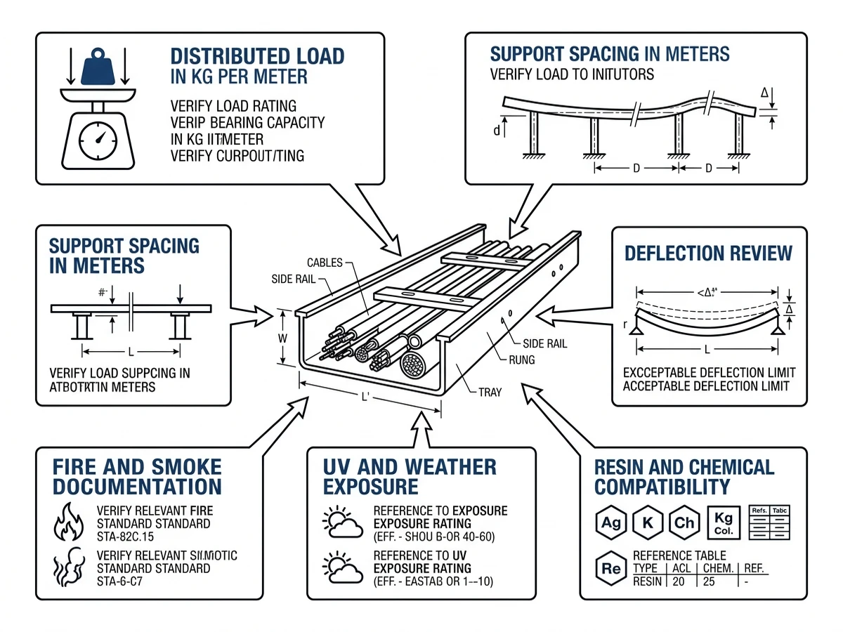
What Engineers Must Verify Before Specifying a Non-Metallic Tray System
A non-metallic tray system is not a like-for-like swap for steel or aluminum. Before specifying FRP and fiberglass cable tray, engineers should verify resin suitability, deflection, thermal behavior, fire performance, grounding, and fitting support.
Environmental exposure and resin suitability
FRP performance depends heavily on resin type. A system suitable for UV and salt fog may not be suitable for alkalis, solvents, or continuous splash duty, so exposure mapping matters more than the generic “FRP” label.
Span, load class, and deflection
Deflection is a common failure point in FRP specifications. Check the manufacturer’s load table using the actual width, cable load, span, and project deflection limit; a wide tray that works in steel may need supports reduced to around 2.0-2.4 m in FRP.
Thermal limits and cable ampacity
FRP does not dissipate heat like metal, so covered and tightly filled sections may need more ampacity review. Open tray forms are usually easier to justify on higher-heat power runs. If you are comparing layouts, Xinma’s article on cable tray size calculation methods is a practical starting point for checking fill and future margin together.
Fire, smoke, and code acceptance
FRP must be checked against project fire criteria, not assumed acceptable because it resists corrosion. Resin and additives determine flame spread and smoke behavior, which may be critical in tunnels, escape routes, or petrochemical areas.
Grounding, bonding, and fault behavior
An FRP tray is not an equipment grounding conductor. Bonding jumpers, armor grounding, shield terminations, and EMC strategy must therefore be designed separately, especially on VFD and mixed power/instrumentation routes.
Fittings, supports, and maintenance access
Straight-section ratings do not automatically apply to elbows, tees, reducers, covers, and splice regions. Verify that the system includes compatible tray fittings and transition hardware and support positions suited to the actual geometry.
Figure 3. FRP cable tray specification should verify load, span, resin compatibility, UV exposure, fire review, and fittings coordination.
Which Tray Geometry Works Best in FRP: Ladder, Perforated, or Solid-Bottom?
For FRP cable tray selection, geometry matters almost as much as material. The best choice depends on cable size, heat release, contamination risk, drainage, and access needs.
Ladder tray: use when heat and access govern
FRP ladder tray is usually best for medium- and large-diameter power cables because the open structure improves airflow, drainage, and inspection access. Small control cables may still need closer rung spacing or added support.
Perforated tray: use when cable support continuity matters
Perforated FRP tray suits control, instrumentation, and communication cables that need more continuous support than ladder tray provides. It offers a balance between airflow and cable support, though debris can accumulate more easily.
Solid-bottom tray: use only when protection justifies the penalty
Solid-bottom FRP tray is mainly for sensitive signal wiring, fiber, or areas exposed to dripping chemicals, dust, or washdown splash. The tradeoff is reduced cooling, so lower fill ratios and extra ampacity review are often needed.
Practical selection logic
Use ladder tray when heat dissipation, drainage, and access are the main drivers. Use perforated tray when smaller cables need closer support with moderate airflow, and use solid-bottom tray only where contamination protection outweighs the thermal penalty.
A practical route may use FRP ladder tray for feeder circuits, perforated tray for instrument multicables, and short solid-bottom sections beneath dirty equipment. If you are still comparing tray forms before locking the material, Xinma’s technical page on cable tray system configurations and its overview of tray dimensions and width/depth selection can help tie geometry back to loading and access.
Common Mistakes When Applying FRP Cable Tray in the Field
Most FRP cable tray failures come from applying FRP as if it were steel. The recurring problems are support spacing, temperature, resin mismatch, misuse as a platform, missing expansion details, and incorrect bonding assumptions.
Carrying over metallic tray support spacing
Reusing steel support spacing without checking FRP deflection is a common error. On 450-600 mm trays with dense loading, excess midspan deflection usually appears first.
Ignoring service temperature
FRP stiffness changes with temperature, so a tray that performs well at 25 °C may deflect much more at 60-80 °C. This often shows up at covers, fittings, and rooftop or process-area runs.
Using the wrong resin for the chemical zone
FRP corrosion resistance is not generic. UV resistance alone does not confirm solvent or alkali resistance, and resin mismatch can lead to surface degradation or cracking near joints.
Treating the tray as a walkway or platform
Cable tray is not a personnel access structure under IEC 61537. Concentrated foot loads can cause cracking, side-rail damage, or permanent deflection.
Omitting expansion provisions on long outdoor runs
FRP expands more than steel, so long outdoor runs need deliberate movement detailing. Without it, bolt-hole elongation, cover distortion, and fitting misalignment can develop.
Assuming metallic bonding behavior still applies
FRP does not provide bonding continuity or fault-current return. If that is not addressed early, grounding and EMC issues often appear late in coordination.
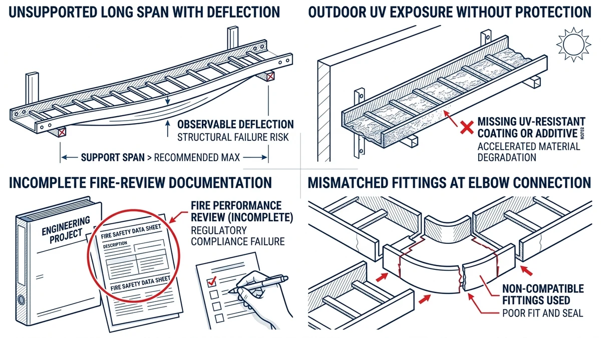
Figure 4. Common FRP cable tray mistakes include overextending spans, overlooking UV exposure, and ignoring fittings and fire-review requirements.
How Xinma Helps Coordinate Corrosion, Loading, Fittings, and Support Decisions
FRP and fiberglass cable tray should be specified as a coordinated system, not just a material choice. Resin affects corrosion resistance, tray profile affects span and deflection, covers affect heat, and fittings alter load paths.
A practical review usually covers four items:
Corrosion and resin review
Match resin type and required fire behavior to the actual chemicals, washdown pattern, UV exposure, and service temperature. A tray suitable for one exposure zone may not suit another.
Loading and support review
Confirm cable weight, future fill margin, support spacing, and deflection limits. In many layouts, changing span from 3.0 m to 1.5 m materially affects tray depth, hanger count, and support steel.
Fittings and transitions review
Check bends, tees, reducers, covers, splice regions, and support positions as one assembly. Transitions are often where serviceability problems appear first.
Installation and maintenance review
Hold-down details, expansion provisions, uplift restraint, access spacing, and inspection practicality should be reviewed together. Covers are usually best limited to locations where contamination risk justifies the extra maintenance effort.
If your project needs FRP and fiberglass cable tray checked against corrosion class, loading, fittings, and support spacing together, Xinma can review the specification and layout before procurement. The value is not generic product promotion. It is reducing coordination risk before fabrication, installation, and commissioning lock in avoidable constraints.
Frequently Asked Questions
When is FRP cable tray a better choice than galvanized steel?
FRP is often the stronger choice when corrosion, chemical washdown, or salt exposure is likely to drive maintenance or replacement. In dry indoor spaces with high mechanical abuse or bonding requirements, steel may still be easier to justify.
Does FRP cable tray need grounding?
The tray itself generally does not serve as a grounding path because it is non-conductive. The project usually needs a separate bonding and protective conductor strategy for equipment, cable armor, and shields.
How do I decide the support spacing for fiberglass cable tray?
Use the manufacturer’s load table with the actual tray width, cable load in kg/m, fitting layout, and project deflection limit. FRP spans often end up shorter than steel spans for the same service load because stiffness, not strength, is the limiting factor.
Is solid-bottom FRP tray suitable for power cables?
It can be, but only when contamination protection justifies the reduced ventilation and any resulting ampacity derating. Open ladder geometry is usually easier to validate on higher-heat power runs.
What should I check before specifying FRP tray in a chemical plant?
Review resin compatibility with the actual chemicals, expected service temperature, support span, fitting ratings, fire criteria, and grounding method. The tray material alone is rarely enough to confirm suitability.
How does outdoor temperature change FRP tray design?
Higher temperature can reduce stiffness and increase thermal movement, which affects span, expansion detailing, and fitting alignment. Long exposed runs usually need more careful movement control than comparable steel systems.
Kevin Zheng
Kevin Zheng is a manager linked to Shanghai Xinma Busway & Cable Tray Co., Ltd. He writes technical content on cable tray systems, installation practice, sizing logic, load classes, and related standards for industrial and infrastructure applications.