How to Evaluate Electrical Cable Tray Suppliers Beyond the Catalog
Evaluating electrical cable tray suppliers means testing engineering capability, not just browsing part numbers. The right supplier helps you size trays for 50–150 kg/m loads, calculate deflection at 2–3 m spans, and advise on ampacity derating and fill ratio under IEC 61537 or NEMA VE 1—before you finalize the cable management system.
You should expect them to review single-line diagrams and tray routing to confirm load class, support spacing, and allowable cable ladder span based on actual cable weight and future capacity (typically ≥30 % spare). In practice, capable suppliers return marked‑up layouts or calculations, not just a bill of materials.
The sections below focus on how to select and coordinate a supplier whose system, ratings, and engineering support will actually work over the life of your project.
Check 1: Standards, Testing, and Structural Design Capability
To evaluate electrical cable tray suppliers, start by checking whether their designs are anchored in recognized standards and verified testing. With a short set of questions, you should be able to confirm which standards they use, what load and deflection data they can provide at your spans, and whether they can issue project‑specific verification for your loading and environment.
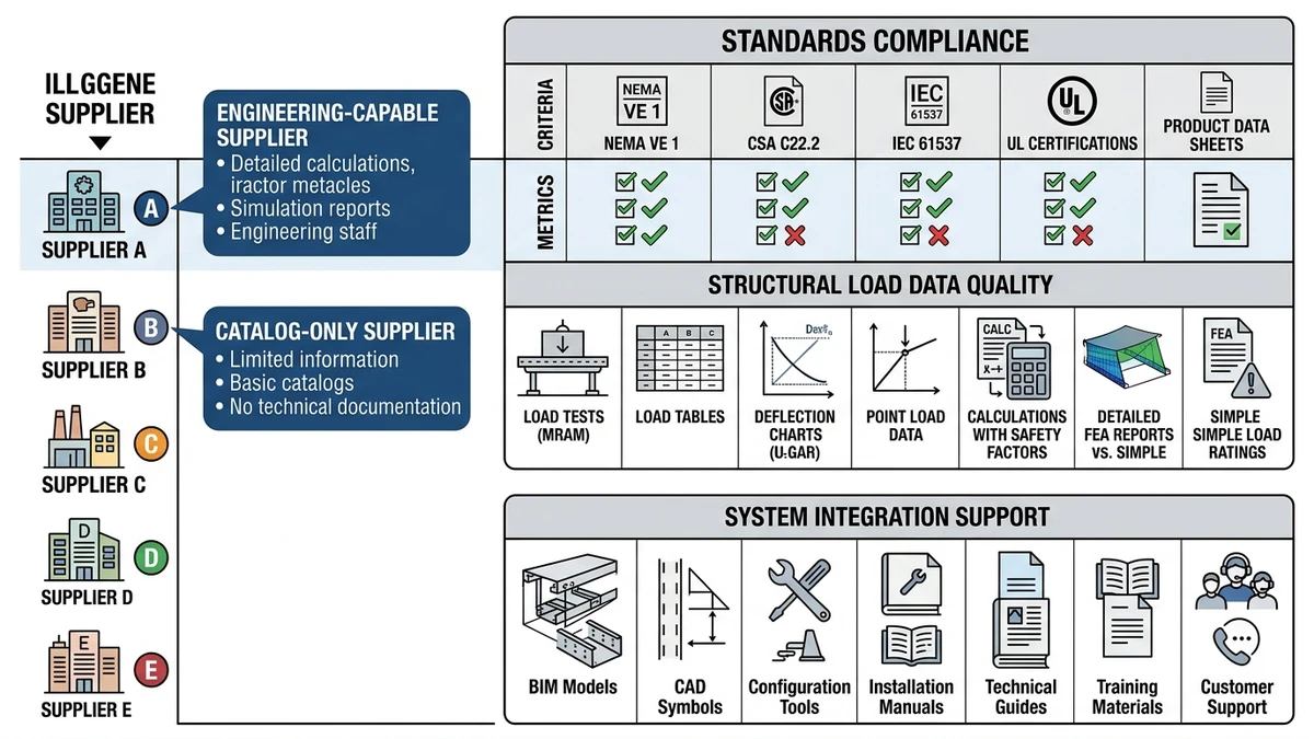
Figure 1. Comparison of electrical cable tray suppliers contrasting a catalog-only vendor with an engineering-capable partner on standards, load data, and project support.
Standards Compliance Checklist
Ask each supplier to document:
Which product lines comply with which standards:
IEC 61537: cable tray and ladder systems (load tests, electrical continuity, corrosion resistance).
NEMA VE 1: loading, deflection, and test methods for metal cable trays.
BS EN 61537 or local GB standards where applicable.
Availability of type test reports, not just declarations.
Clear load class markings (e.g., 100 kg/m, 200 kg/m) tied to a defined test span such as 2.0 m or 3.0 m.
If a tray’s “200 kg/m at 3 m” rating is actually derived from a 1.5 m test span with simple extrapolation, midspan deflection and stress at 3 m can be roughly double what you expect, increasing cable strain and vibration risk.
[Expert Insight]
– IEC 61537 load tests (Annex E) define how deflection is measured and when to stop loading; use these to challenge unclear catalog ratings.
– Ask suppliers to highlight any deviations from IEC or NEMA test setups; small differences in support conditions can significantly change apparent capacity.
Structural Design and Load Data
Minimum structural data you should insist on:
Rated uniformly distributed load (UDL) in kg/m at a given span and allowable deflection (commonly L/200 or L/250).
Width‑dependent ratings, since 300 mm and 600 mm ladders rarely have the same capacity at a given span.
Treatment of additional loads: snow, wind uplift, and maintenance or walk‑on conditions if applicable.
Increasing span from 2.0 m to 3.0 m can increase deflection by ~2–3× for the same UDL, so a tray that is stiff at 2.0 m may exceed the L/200 limit at 3.0 m. If you add a solid cover (often 4–6 kg/m for a 600 mm tray) plus ice or snow, but the supplier has no method for combining these loads, support spacing is guesswork.
Testing Scope and Methods
Request specifics on how testing is performed and documented:
Load test setup: span length, support type, load application method, load increments, and failure/deflection criteria.
Corrosion testing: salt spray duration, coating thickness in µm, and any post‑test mechanical checks.
Electrical continuity: measured resistance per joint and assumptions for earthing/bonding.
Without consistent test methods and clear documentation, you cannot meaningfully compare two “150 kg/m” ratings or confidently size supports, seismic bracing, or bonding conductors around them. IEC 61537 provides the baseline for test configurations and performance requirements for cable tray systems (see the publication page at IEC 61537 publication page).
Supplier Engineering Support
Once standards and test data are clear, check whether the supplier can work at your project’s level of detail:
Span selection: can they confirm whether 2.5 m vs 3.0 m spans are acceptable for your 600 mm tray at an 80 kg/m cable load while respecting the specified L/200 limit?
Special cases: can they perform project‑specific checks for outdoor runs, seismic zones, or heavy power cable bundles ≥20 kg/m per phase?
Use when:
– You need structural verification tied to actual cable weights, covers, and environmental loads.
Avoid when:
– The supplier can only quote catalog spans with no ability to adjust for real loads or site conditions.
Check before specifying:
– Do they issue calculation sheets or signed verification notes, not just verbal confirmation?
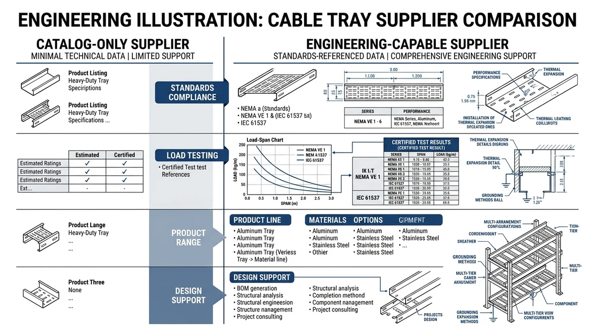
Check 2: Product System Breadth and Integration with Your Project
“System breadth” is whether the supplier’s cable management system actually covers your route with compatible tray types, fittings, supports, and accessories. “Integration” is how well that system fits your voltages, environments, structures, and construction sequence without constant custom fabrication.
Figure 2. Typical cable tray load-span-deflection relationship with accompanying IEC and NEMA standards checklist for supplier evaluation.
Core Tray Families and Ratings Must Match Your Use Cases
Confirm that the standard portfolio covers your sizes and ratings:
Ladder, perforated, and wire mesh tray options from about 100–800 mm width, with load classes up to 150–200 kg/m at 2.5–3.0 m spans.
Corrosion options:
Pre‑galvanized for dry indoor environments.
Hot‑dip galvanized for outdoor or damp conditions.
Powder‑coated or stainless steel (e.g., 304/316) for more aggressive areas.
Voltage segregation accessories (dividers, multi‑compartment trunking) for mixed‑voltage corridors.
Ladder trays suit heavy power circuits and heat dissipation; perforated trays suit mixed smaller cables; wire mesh is flexible for short, light‑duty, congested areas. Using light‑duty perforated or mesh trays for long outdoor spans with heavy MV cables and covers typically leads to forced span reductions or extra supports.
If you require 90 m of outdoor 600 mm tray at 3 m span but the catalog only certifies 100 kg/m at 2 m, you either overbuild supports or accept non‑verified loading—both inferior to selecting a tray rated at your actual span.
[Expert Insight]
– Mis‑matching tray family and load class is a common cause of on‑site span reductions and added supports that clash with HVAC and pipework.
– Early confirmation of tray type, width, and rated span usually removes multiple rounds of MEP coordination.
Fittings, Supports, and Accessories as a Single System
A strong supplier catalogues fittings and supports that are type‑tested with each tray family:
Fittings: bends, tees, reducers, and vertical elbows in standard widths and radii (e.g., 300, 600, 900 mm) to respect cable minimum bend radius, especially for MV cables.
Supports: wall brackets, trapeze hangers, cantilevers, and stand‑off brackets rated for tray + cable + cover, including appropriate safety factors.
Accessories: earthing kits, splice plates, expansion joints, drop‑outs, and barriers tested with the system.
Factory fittings provide consistent stiffness and coating, simplifying structural and electrical documentation; extensive site‑fabricated fittings add variability and are harder to prove compliant. Standardize factory fittings on repetitive or critical routes, and avoid relying on site‑fabricated fittings for high‑load or fire‑separated runs unless you have project‑specific details.
Most misalignment and clash problems occur at fittings and supports, not straight runs, so a coordinated system significantly reduces field cutting and custom brackets.
Integration with Project Structures and Interfaces
Assess how well the system connects to your building structure and coordinates with other services:
Structural integration:
Standard details for steel beams, concrete soffits, and lightweight roofs, with anchor spacing and edge distance guidance.
MEP coordination:
Tray depths and side rail heights that fit under ducts and above ceilings while maintaining clearances from sprinklers and access ways.
Future modification:
Provision for drop‑outs, additional splice options, and extra tiers so that 40–50 % extra cable load can be added later.
A three‑tier stack with 300 mm spacing can raise cable core temperature by several degrees Celsius for heavily loaded power circuits, so a supplier who can advise on stacking limits and separation helps you avoid ampacity issues.
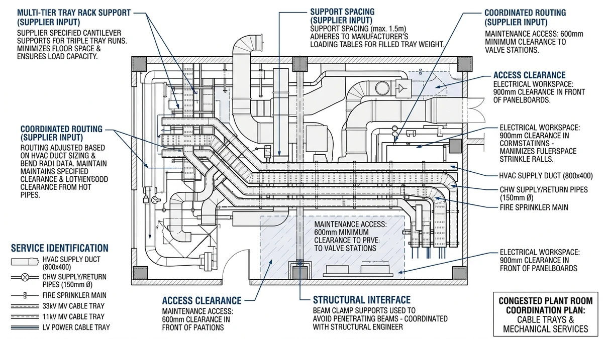
Check 3: Field-Proven Support for Design, Installation, and Maintenance
Field‑proven support is what turns steel into a working cable management system. When you assess electrical cable tray suppliers, verify how they support design, installation, and maintenance.
Figure 3. Coordinated electrical cable tray routing in a congested plant room, illustrating interaction with supports, piping, and HVAC under supplier-guided design.
Design Support: From Layout to Load Checks
Request concrete evidence that the supplier can help with:
Tray sizing and fill:
For example, confirming that a 300 mm ladder tray at 3 m span carries a 70 kg/m load within the L/200 deflection limit under IEC 61537 assumptions.
Fittings and transitions:
Proposals for specific bends, reducers, and tees with minimum cable bend radius clearly indicated.
Thermal and derating advice:
Commentary on ampacity impact for stacked trays and when increased separation or ventilation is advisable.
Use when: the supplier returns marked‑up layouts or calculation sheets within a few working days for typical routes.
Avoid when: response is limited to catalog extracts with no project‑specific checks.
Installation Support: Details That Prevent Site Rework
On site, good support translates into fewer surprises:
Install guides and typicals:
Standard details for brackets, trapeze hangers, and splice joints, including maximum spans and allowable cantilever lengths.
Guidance for vertical drops, offsets, and expansion joints across building movement joints.
Handling and cutting rules:
Instructions on field cutting, repair of hot‑dip galvanizing (zinc‑rich paints, minimum overlap), and bolt tightening torque to maintain rating.
Limits on how many rungs or perforations can be cut away at supports or fittings.
Ask to see a sample installation manual and verify that it references current standards (IEC 61537, NEMA VE 2 ) rather than generic sketches.
Maintenance and Lifecycle Support
Suppliers with real field experience usually have clear guidance on:
Inspection intervals, e.g., 12–24 months in corrosive outdoor zones, with longer intervals for benign indoor areas.
Typical failure points such as splice plates near building joints, supports under penetrations, and low points where water accumulates.
Spares and compatibility lists so future replacements remain compatible even if catalog generations change.
Maintenance issues are often concentrated at non‑standard site‑fabricated fittings and overloaded cantilevers, so a supplier able to identify and mitigate those risks early is valuable.
Applying These Checks with Xinma: Coordinating Loading, Corrosion, and Fittings in Your Specification
When you apply these checks with a supplier such as Xinma, three aspects must be coordinated as one system: total loading, corrosion protection, and fittings geometry. Treating them as separate catalog choices leads to inconsistent spans and unexpected derating.
Coordinating Loading and Support Spans
Switching from a 100 kg/m to a 150 kg/m cable load on a 400 mm ladder tray at 3.0 m spans can push deflection beyond an L/200 limit unless you either upgrade tray section or shorten spans (e.g., to 2.5 m). A 50 % load increase can move deflection from about 8–10 mm toward 15 mm or more at 3.0 m, raising cable sag and splice joint stress.
A supplier like Xinma should be able to check these values against IEC 61537 load classes and advise whether to upgrade tray section or reduce span. For projects planning future loading, Xinma’s resources on cable tray sizes and fill planning and cable tray size calculation can help cross‑check early assumptions.
For route transitions and component matching, Xinma?s cable tray fittings range gives specifiers a direct way to compare elbows, tees, reducers, and splice details with the straight tray sections.
Matching Corrosion Class to Material and Coating
If your route moves from indoor C2 to outdoor C4 corrosion exposure, pre‑galvanized or thin‑coated systems may no longer be adequate. You may need hot‑dip galvanized steel with sufficient zinc thickness or stainless steel (e.g., 304 vs 316) where chlorides or aggressive chemicals are present.
Use when:
– Hot‑dip galvanized steel for most outdoor industrial areas without heavy chlorides.
– Stainless 316 for coastal environments or chloride‑bearing atmospheres.
Avoid when:
– Using pre‑galvanized only for outdoor coastal or chemical areas, where coating life may be too short.
Check before specifying:
– Ask for corrosion test data (salt spray hours, coating thickness) and recommended environments for each finish.
Xinma’s cable tray product range and ladder cable tray line cover multiple material and coating combinations; selecting the right one depends on site corrosion category and required service life.
Fittings Geometry, Bend Radii, and Joint Stresses
Fittings geometry can over‑stress joints or breach minimum bend radii if not coordinated with cable type and tray load class:
Tight bends can reduce cable bend radius below recommendations, especially for MV or armored cables.
Poorly supported tees and reducers localize bending and vibration at splice plates.
If you specify a 300 mm radius bend where the minimum required is 600 mm (e.g., 10× OD for a 60 mm cable), the radius is effectively halved, increasing mechanical strain and long‑term insulation damage risk.
Use when:
– Standard elbows and tees meet or exceed cable minimum bend radius and are supported within tested span limits.
Avoid when:
– Using non‑standard, site‑welded fittings in high‑load or high‑vibration sections.
Check before specifying:
– Confirm that fittings, covers, and splice plates are structurally matched and carry the same load class as straight sections, especially on 600–800 mm ladders.
For coordinated routing, Xinma can support you from early concepts (using references like the electrical cable tray guide) through to final support layouts informed by their cable tray support design notes.
Coordinated Specification Review with Xinma
When you want your specification reviewed as a coordinated system rather than a list of parts, Xinma can help you:
Verify load classes, midspan deflections, and support spans for tray + cable + cover combinations under your ambient temperatures and fill ratios.
Select compatible fittings and covers that preserve mechanical strength and cable bend radii.
Choose material and coating options matched to your corrosion category and service life.
Define support spacing, splice plate locations, and expansion joints clearly on drawings so that installation and maintenance stay within tested limits.
This level of supplier engagement typically reduces late design changes and on‑site rework where load, corrosion, and routing constraints interact.
How this page differs from related XMQJ guides
This page focuses on its stated search intent. For product-level selection, start from Xinma Cable Tray Systems and then compare the related engineering guides linked above.
Engineering Evidence and Verification Sources
This article has been updated with explicit source and procurement checks so engineering, EPC, and purchasing teams can verify the recommendations instead of relying only on generic product descriptions. For project use, treat the table below as a starting evidence map and confirm the final requirements against local codes, consultant drawings, and supplier submittals.
Use this source to verify standards, product scope, installation assumptions, or supplier evidence before final specification.
Buyer Verification Checklist
Request drawings that show tray width, depth, side rail profile, bend radius, fittings, and support spacing.
Ask for load tables or engineering assumptions that state test span, load class, and deflection criteria.
Confirm material grade, surface finish, coating method, and corrosion exposure assumptions before comparing prices.
Check whether accessories such as covers, couplers, reducers, clamps, grounding jumpers, and brackets are included.
For EPC or export orders, review packaging, labeling, inspection records, and drawing revision control before shipment.
Frequently Asked Questions
How do I verify a cable tray supplier’s load ratings are usable for my spans?
Ask for type test reports that state the tested span, load in kg/m, and deflection criteria (e.g., L/200), then compare these directly with your intended span and cable weight instead of relying only on catalog tables.
What is the difference between ladder, perforated, and wire mesh trays for heavy power circuits?
Ladder trays generally suit heavier power cables due to higher stiffness and ventilation, while perforated and wire mesh trays are better for lighter mixed cables but often require shorter spans or lower loads for the same deflection limits.
How should I account for future cable additions when selecting cable tray size?
Size trays so that the initial cable installation occupies roughly 50–60 % of the allowable fill area, leaving capacity for future cables without exceeding load class or forcing major support modifications.
When should I choose stainless steel cable trays instead of galvanized steel?
Stainless steel trays are typically chosen in coastal, chemical, or high‑chloride environments where galvanized coatings may not provide sufficient long‑term corrosion resistance at the required service life.
How can I reduce installation problems with cable tray fittings on site?
Standardize on factory‑made bends, tees, and reducers for most junctions, and have the supplier review your layout so supports are placed close to fittings and expansion joints, minimizing site‑fabricated pieces and unplanned cantilevers.
Kevin Zheng
Kevin Zheng is a manager linked to Shanghai Xinma Busway & Cable Tray Co., Ltd. He writes technical content on cable tray systems, installation practice, sizing logic, load classes, and related standards for industrial and infrastructure applications.