Address
304 North Cardinal St.
Dorchester Center, MA 02124
Work Hours
Monday to Friday: 7AM - 7PM
Weekend: 10AM - 5PM
Address
304 North Cardinal St.
Dorchester Center, MA 02124
Work Hours
Monday to Friday: 7AM - 7PM
Weekend: 10AM - 5PM
Get premium quality cable management systems directly from the manufacturer.
Fill out the form below to receive our catalog and pricing.
An electrical cable tray is the structural backbone of any serious cable management system — yet it gets specified incorrectly on more projects than most engineers would admit. Choose the wrong type and cables overheat. Skip the rail height spec and the tray sags under load. Ignore seismic coordination and the whole run fails inspection.
This guide covers what an electrical cable tray is, how each type performs under real load conditions, which materials suit which environments, how to size a system before procurement, and which standards govern every decision.
An electrical cable tray is an open, rigid structural system that supports and routes insulated power conductors, control cables, and communication lines along a fixed path — without enclosing them in sealed pipe. It holds cables in place, keeps them organized, and allows direct access along the entire run for inspection, additions, or re-routing without dismantling anything.
IEC 61537 (Cable Management — Cable Tray Systems and Cable Ladder Systems) is the governing international standard. Section 8 sets the critical structural threshold: under rated load, a compliant tray must not deflect more than 1/100 of the support span. At a standard 1,500 mm span, that limits midspan deflection to 15 mm — a single clause that eliminates most improvised channel solutions from regulated project specifications.
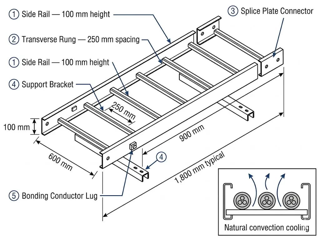
A typical cable tray assembly has three primary elements:
Conduit encloses cables inside rigid or flexible pipe. Each circuit gets its own pipe, its own fittings, its own pull points. Accessing or modifying a conduit run means cutting, pulling, and replacing. A wireway provides four-sided enclosure with removable covers — more accessible than conduit, but still enclosed.
A cable tray manages entire cable populations as a system. Cables lie visible and accessible. Adding a new cable means laying it in the next available space. No demolition, no cutting, no confined-space pull points.
The crossover point is consistent across project types: once a run carries approximately 12–15 cables, cable tray economics and thermal management advantages outweigh conduit on nearly every measure. In a Tier III data center fit-out in Shanghai (2024), switching from conduit to 600 mm-wide ladder cable trays reduced cable routing labor by approximately 35% and cut re-routing time during a subsequent network expansion from three days to under six hours — because cables were accessible without opening walls or pulling new conduit.
[Expert Insight]
- The L/100 deflection limit in IEC 61537 Section 8 is a structural integrity threshold, not a comfort margin — exceeding it risks permanent rail deformation and cable jacket stress at support edges.
- Conduit fill rules (e.g., NEC Chapter 3) and cable tray fill rules (NEC Article 392) are calculated differently; engineers moving between systems must recalibrate their fill ratio assumptions entirely.
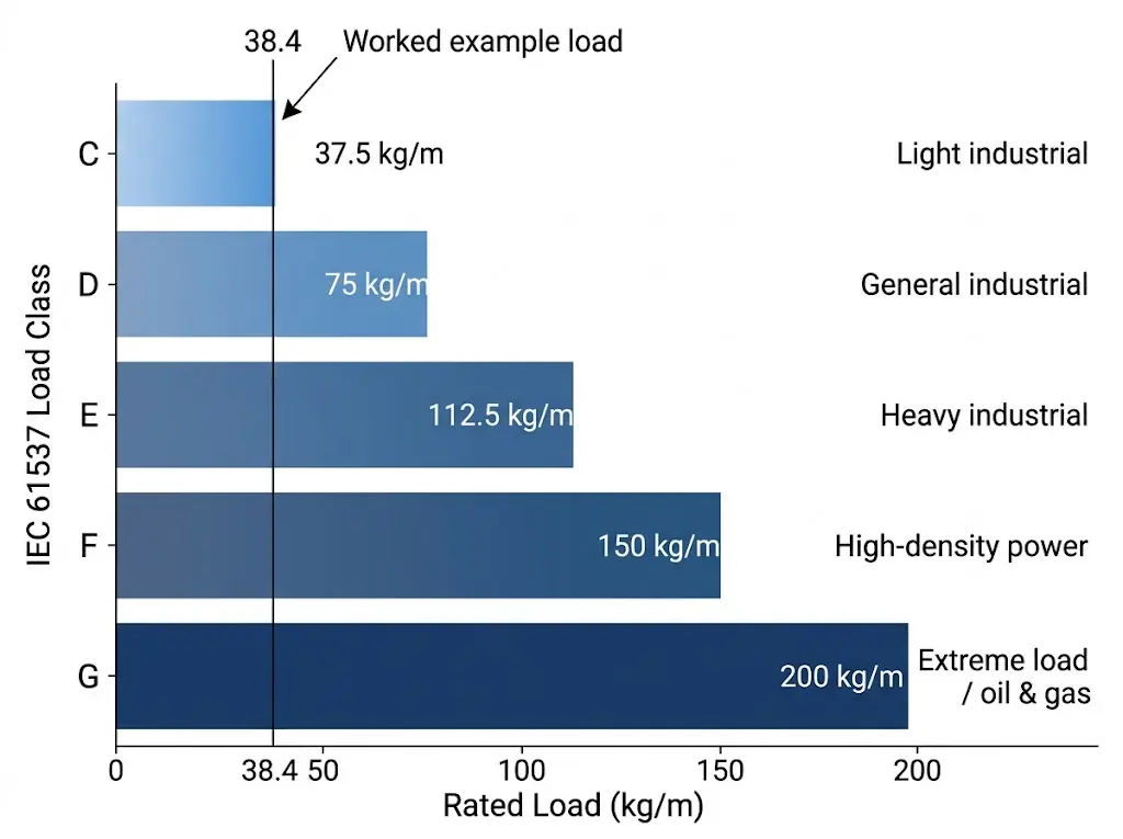
- IEC 61537 load classes A through D (50–200 kg/m) are proof-load ratings at a 3 m reference span — the same tray at a 1.5 m span carries substantially more before hitting the deflection limit.
Selecting the wrong tray type is one of the most common and costly specification errors in electrical fit-out. Each type has a defined structural profile, a heat dissipation behavior, and a practical use range. The five types are not interchangeable.
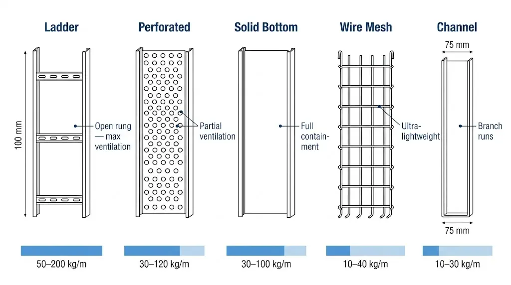
Two longitudinal side rails connected by transverse rungs, typically spaced 150–300 mm apart. The open rung structure gives maximum ventilation — directly preserving cable ampacity on high-voltage power runs where heat buildup causes derating under IEC 60364-5-52.
Rail height is the primary stiffness variable. Doubling rail height from 50 mm to 100 mm typically reduces midspan deflection by a factor of 4–6 due to the second moment of area effect — which is why specifying width alone is a critical error. Explore full load and span data on the Xinma ladder cable tray product page.
Solid side rails with a perforated base panel, perforation ratio typically 30–50% of base area. It balances cable containment with partial ventilation.
The perforated base retains small-diameter cables — including fiber and Cat 6A — that would sag through ladder rungs, while still dissipating enough heat for bundled LV circuits. See the Xinma perforated cable tray range for width and perforation ratio options.
No ventilation openings. The full enclosed base protects cables from dripping water, falling debris, and chemical splash.
The thermal penalty is real. Solid trays can reduce cable ampacity by 15–25% compared to ladder tray in the same installation, depending on bundle diameter and ambient temperature. Designers must apply grouping derating factors. Full specifications are available on the Xinma solid cable tray page.
Welded wire basket, typically galvanized or stainless steel. Extremely lightweight — under 3 kg/m for 300 mm width — and fast to cut and modify on-site.
Single-piece U-profile, widths typically 50–150 mm. Used for branch runs, instrument cable separation, or routing from main tray to individual equipment drops.
[Expert Insight]
- Rung spacing on ladder trays affects small-cable sag: cables under approximately 12 mm outer diameter should not be routed on 300 mm rung spacing without a cable support liner or perforated insert.
- Solid-bottom trays in horizontal runs should have drain holes at low points in outdoor installations — pooled water accelerates zinc coating degradation from the inside.
- Wire mesh trays are not a low-cost substitute for perforated trays in power cable applications; their load ratings and grounding continuity characteristics are fundamentally different.
Material selection follows environment, not budget preference. Specifying the cheapest material for a corrosive environment costs more in maintenance and replacement than the initial premium for the correct one.
| Property | Hot-Dip Galvanized Steel | Aluminum Alloy | Fiberglass (FRP) |
|---|---|---|---|
| Tensile strength | 300–550 MPa | 150–310 MPa | 200–350 MPa (directional) |
| Corrosion resistance | Good — indoor/mild outdoor | Good — non-chloride environments | Excellent — chemical, marine |
| Weight vs. steel | Baseline (100%) | ~35% of steel | ~40% of steel |
| Max service temp | ~400°C structural | ~150°C structural | ~130°C (standard resin) |
| Electrical continuity | Yes — usable as EGC with bonding | Yes | No — separate EGC required |
| Typical application | Industrial, commercial, general | Petrochemical, offshore, food-grade | Wastewater, chemical, marine |
Hot-dip galvanized steel dominates volume because it hits the best cost-per-load-capacity point for most projects. The zinc coating minimum of 45 µm per ISO 1461 provides 20–40 years of outdoor corrosion resistance under typical industrial exposure. In a 2024 offshore wind substation project, switching from galvanized steel to FRP cable ladders on the weather-exposed cable deck eliminated corrosion-related maintenance calls over the first 18 months — the kind of outcome that justifies the 2–3× material cost premium in salt-spray environments.
Aluminum becomes cost-competitive when weight drives the decision — offshore topsides, elevated cable bridges, or any structure where dead load is a structural concern. FRP is the only rational choice in concentrated acid or chlorine atmospheres, where even stainless steel corrodes at weld zones.
Tray sizing is not aesthetic. Undersized trays create heat buildup, mechanical overload, and failed inspections. Three parameters must be checked in sequence — skipping any one of them is how field problems start.
NEC Article 392.22 and IEC 61537 Annex B both impose maximum cross-sectional fill. The working rule for most installations:
Sum the cross-sectional area of all cables from manufacturer datasheets, add 20–25% for future capacity, then select tray width accordingly. A 400 mm wide × 100 mm deep tray has a usable interior area of approximately 40,000 mm²; at 50% fill, the maximum cable cross-section is 20,000 mm².
Filling trays to 95% capacity at commissioning is the single most common cause of disruptive re-work within three to five years.
Distributed load (kg/m) = total cable mass per meter of run, calculated from each cable’s kg/m value in the manufacturer datasheet, summed across all cables in the tray.
Apply a safety factor to the calculated load:
In seismic installations, tray load class selection and brace spacing are interdependent. A tray sized for standard 1,500 mm spans may require a heavier rail section when brace spacing is reduced to 750–900 mm for seismic compliance. Seismic brace design must be coordinated with tray specification — see Xinma seismic bracing systems for zone-specific requirements.
Under IEC 61537, maximum midspan deflection under full rated load must not exceed span/100. A 1,500 mm span tray must not deflect more than 15 mm at midspan. Exceeding this causes cable stress, joint misalignment, and progressive sagging over time.
Deflection is governed by rail height, not tray width. Doubling rail height from 50 mm to 100 mm typically reduces midspan deflection by a factor of 4–6. Always specify rail height and width together when ordering — a width-only specification is incomplete and leads to the most common structural sizing error in the field.
In a pharmaceutical manufacturing fit-out in Suzhou (2024, 12,000 m² clean-room facility), the engineering team verified all three parameters before installation. Bracket spacing was set at 1,800 mm against IEC 61537 Class C load tables, eliminating field rework from tray deflection and saving an estimated 480 installation hours across the project.
| Standard | Jurisdiction | What It Governs |
|---|---|---|
| IEC 61537:2006+AMD1 | International | Mechanical performance, load classes A–D, test methods, marking |
| NEMA VE 1-2017 | North America | Metallic cable tray — load, deflection, dimensions, materials |
| BS EN 61537 | UK / Europe | IEC 61537 adopted with UK national annex |
| GB/T 23639 | China | Cable tray systems [VERIFY: current edition and scope] |
| NEC Article 392 | USA (NEC jurisdiction) | Installation rules, fill ratios, bonding requirements |
| IEC 60364-5-52 | International | Cable ampacity, grouping derating, thermal installation factors |
For projects operating under Chinese GB standards alongside IEC — common on export-specification industrial projects — GB/T 23639 covers cable tray systems specifically. Where the two standards differ on load class definitions or test methodology, project specifications should state which standard takes precedence at each stage of verification.
The authoritative public source for IEC 61537 scope, amendment history, and current edition status is the IEC official webstore: https://webstore.iec.ch
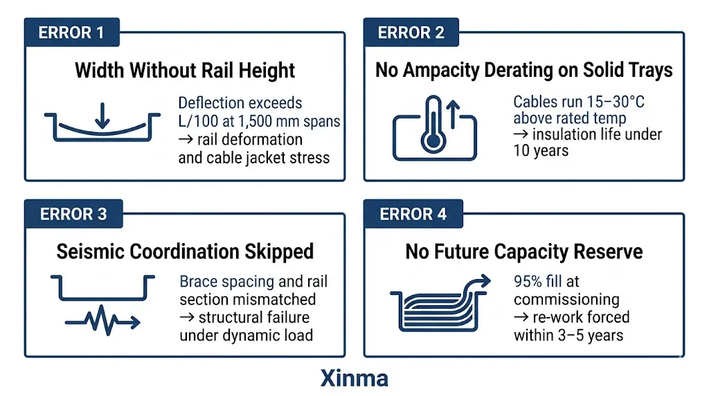
These are not edge cases. Each one appears regularly on projects across industrial, commercial, and infrastructure sectors.
A 400 mm wide, 50 mm rail tray at 1,500 mm spans will exceed deflection limits under moderate cable load. Rail height governs stiffness. Specifying only width produces an incomplete procurement document and an under-engineered installation.
Bundled cables in an enclosed tray run hotter than the same cables in a ladder tray. Failure to apply IEC 60364-5-52 grouping derating factors can result in cables running 15–30°C above rated temperature — shortening insulation life from 30+ years to under 10 years in severe cases.
In seismic zone projects, tray size selection and brace spacing are interdependent. A tray sized for load capacity at standard 1,500 mm spans may need heavier rail sections if brace spacing is reduced to 900 mm for zone compliance. Treating these as separate design tasks produces conflicts that are expensive to resolve during installation.
Standard practice is to leave 25–30% of tray cross-section empty at handover. Projects that fill trays to 90–95% capacity at commissioning almost always require disruptive structural or thermal re-work within three to five years — typically when the first system expansion hits an already-full tray.
The selection sequence is straightforward once load, environment, and applicable standard are defined.
Xinma supplies the full cable tray range — ladder, perforated, solid bottom, and all associated fittings — manufactured to IEC 61537 standards with load certification documentation suitable for third-party review.
For project-specific sizing support, load certification documentation, or technical consultation on seismic coordination, the complete product range and contact details are available through the links below.
→ Browse the complete cable tray range
→ Cable tray fittings and accessories
A cable ladder is one specific type within the broader cable tray family — it uses two longitudinal side rails connected by transverse rungs, resembling a ladder laid flat. Other members of the family include solid-bottom trays, perforated trays, and wire mesh trays. The key practical distinction is ventilation: ladder trays allow maximum airflow around cables, which is why IEC 61537 treats them as a distinct sub-category with their own load and deflection classifications.
Load capacity depends on tray type, material, rail height, and support span. IEC 61537 defines four load classes from Class A at 50 kg/m through Class D at 200 kg/m, each tested at proof load over a 3 m reference span. A standard hot-dip galvanized steel ladder tray at 600 mm width spanning 1,500 mm between supports typically carries 100–150 kg/m within allowable deflection limits — though the exact figure should always be verified against the manufacturer’s span-load table for the specific rail height specified.
Metallic cable trays must be bonded to the facility earth system to maintain a continuous fault-current return path. Splice plate connections alone do not guarantee electrical continuity across joints — dedicated bonding jumpers are required at each splice and at regular intervals along the run. FRP trays carry no fault current and always require a separate equipment grounding conductor installed within or alongside the tray.
Outdoor installation is straightforward provided the correct material and finish are selected. Hot-dip galvanized steel to ISO 1461 (minimum zinc coating 45 µm) suits most industrial outdoor environments. In coastal, offshore, or chemical plant settings where chloride or acid exposure is sustained, FRP or stainless steel Grade 316L trays are typically specified to avoid coating degradation within the first few years of service.
A maximum fill ratio of 50% of the usable tray cross-sectional area is the standard working limit for power cable installations under both NEC Article 392 and IEC 61537 Annex B guidance. Staying at or below this threshold preserves heat dissipation, maintains ampacity ratings, and leaves room for future cable additions without requiring tray replacement or re-support.
Rail height is the primary determinant of tray stiffness. Because stiffness scales with the second moment of area, doubling rail height — for example, from 50 mm to 100 mm — typically reduces midspan deflection by a factor of 4 to 6 under the same distributed load. Specifying tray width without stating rail height produces an incomplete procurement document; the same width tray in two different rail heights can have dramatically different structural performance at identical spans.
Ladder cable trays at 600 mm width are commonly used for main power spine routes in data centers due to their high load capacity and maximum ventilation. Wire mesh trays suit structured cabling and patch runs where light loads and easy on-site modification are priorities. The two types are often used together — ladder tray for power distribution at ceiling level, wire mesh for data cables under raised floors — with physical separation maintained to limit electromagnetic interference between power and signal runs.
Standards references reflect published editions as of Q1 2026. Verify current amendment status through the IEC Webstore or your applicable national standards body before final specification.