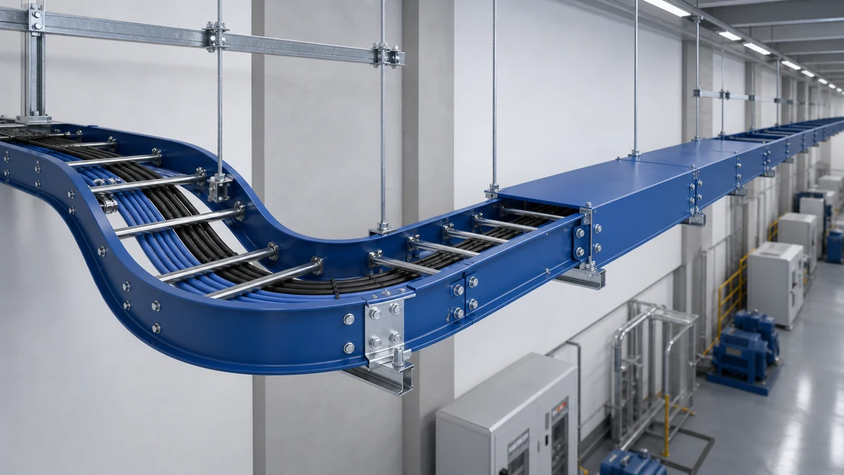
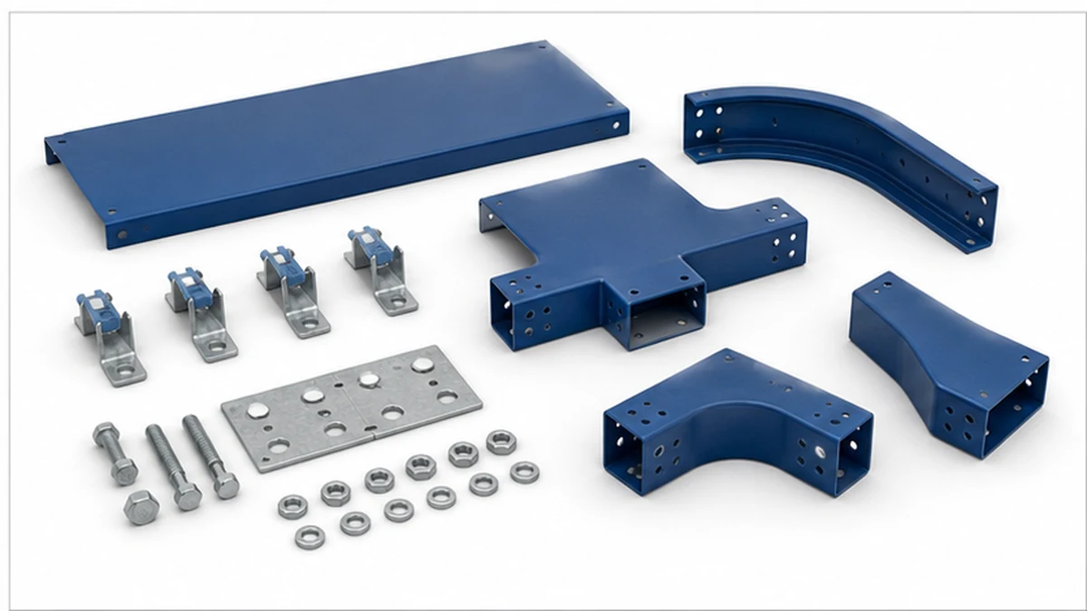
Electrical cable tray components work as one support system. The tray section, side rails, rungs, fittings, splice plates, covers, supports, clamps, and bonding hardware all need compatible dimensions and finishes. A tray order that specifies only width and material often reaches site with missing parts, uncertain interfaces, or an incomplete bill of materials.
For EPC and MEP teams, the useful starting point is the Xinma cable tray system range. Confirm the route, cable schedule, environment, support arrangement, and required accessories before issuing the purchase order. The target is not simply a tray section. It is an installable, inspectable route.
The Core Components of a Cable Tray System
Side Rails
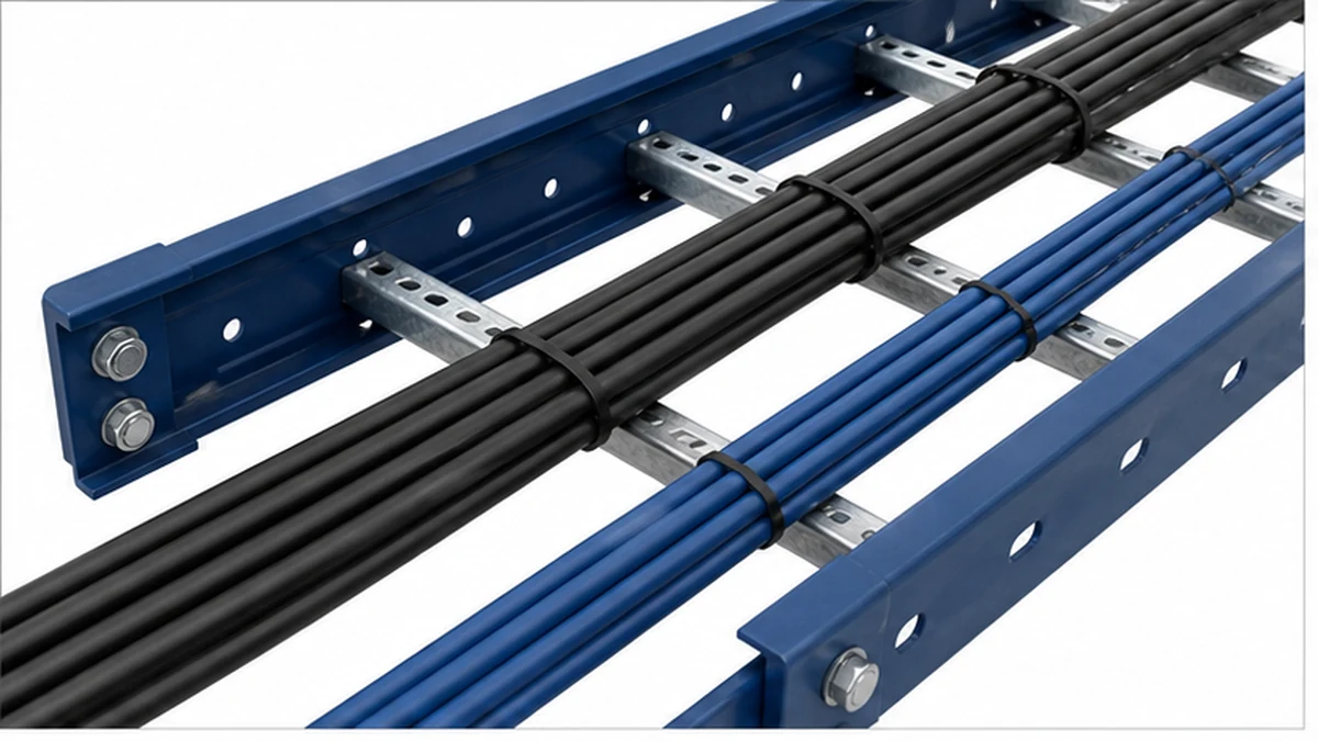
Side rails are the longitudinal structural members. Their depth, profile, material thickness, and return flanges determine how the tray behaves between supports. A deeper rail can provide a different load and span capability, but the rated load must always be read from the selected manufacturer’s data rather than inferred from rail depth alone.
At incoming inspection, compare rail depth, section length, punching pattern, coating, and visible weld condition against the approved drawing. Splice holes that do not align or a substituted rail profile can prevent the specified splice plate from seating correctly.
Rungs or Bottom Members
In a ladder tray, rungs connect the side rails and provide individual cable bearing points. Rung pitch affects cable support, access, and the fit of cable cleats or separators. Small control cables and fiber routes may need closer support than a route carrying only large power cables. The appropriate pitch comes from the cable diameter, routing method, and approved tray-system data.
Rungs should be smooth where cables touch them. Inspectors should look for sharp edges, exposed burrs, cracked welds, and localized coating damage. These are cable-jacket risks even when the tray section otherwise looks complete.
Side rails and rungs provide the cable bearing structure.
Covers and Retention Clips
Covers manage exposure rather than replace a suitable tray selection. Solid covers can reduce falling-debris exposure and help protect overhead runs. Ventilated covers preserve more airflow where that is required. Hinged or removable covers support routes that need repeated access.
The cover part number must match the nominal tray width and rail geometry. Include the retaining clips, screws, or straps in the BOM. A cover delivered without its retention method is not a finished component package. For routes that need a more enclosed solution, compare the tray body and cover arrangement with the appropriate perforated cable tray option, then confirm drainage and thermal requirements for the installation.
Fittings That Preserve the Route Geometry
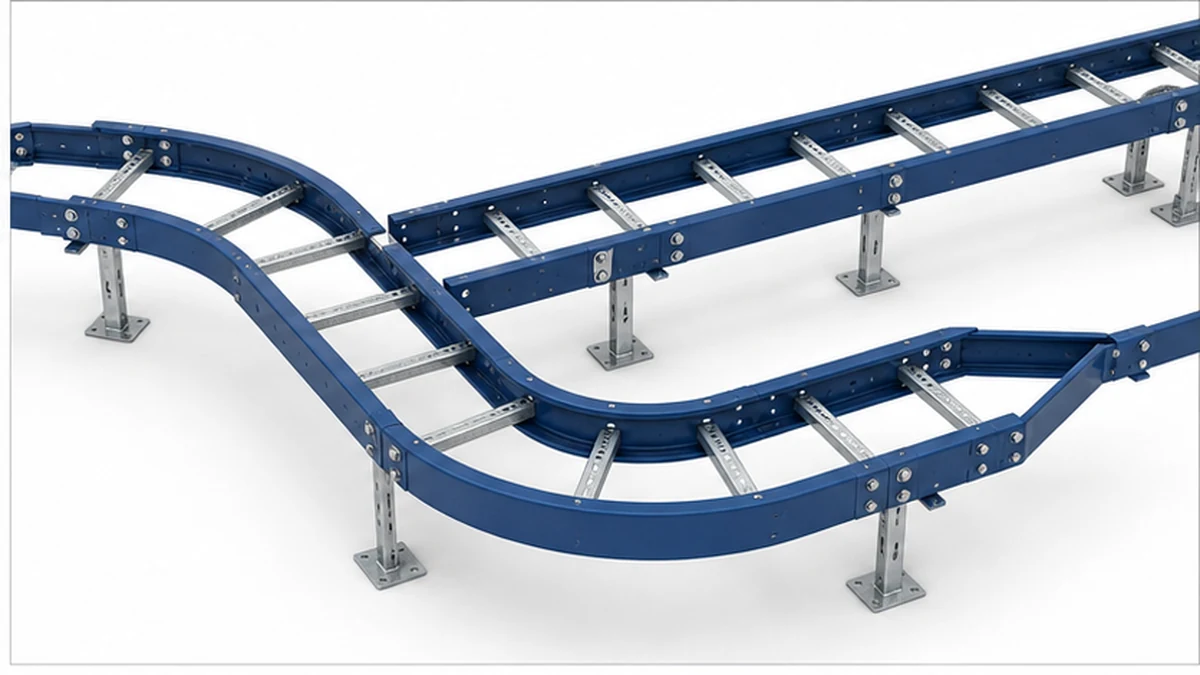
Fittings manage direction, level, and width changes. Their main types are horizontal elbows, vertical elbows, tees, crosses, and reducers. Use factory-matched fittings where possible. An improvised field bend may alter cable bend radius, create unprotected edges, or make the splice pattern incompatible with the straight sections.
Horizontal and vertical elbows should be selected around the cable’s stated bend limits, not only around available room in the ceiling. At tees and crosses, review the cable density at the junction because it can be higher than on each incoming straight route. Reducers need to be shown at every width transition so cables do not bridge an unsupported step.
The cable tray fittings page is the correct compatibility check for elbows, tees, risers, reducers, splice plates, and related route hardware. Keep the tray section and fittings in the same material and finish family unless the design explicitly addresses galvanic or corrosion risk.
Factory-matched fittings preserve route geometry.
Supports, Splice Plates, and Bonding Hardware
Supports transfer tray load into the structure. Common arrangements include trapeze supports, wall brackets, floor supports, and structural hangers. The tray rating cannot be separated from the support arrangement. Verify support spacing, rod and strut selection, structural anchors, and clearance for future cable installation.
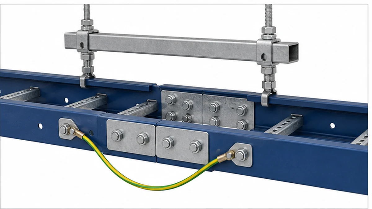
Splice plates keep adjacent tray sections aligned. They also affect continuity where the electrical design uses the tray as an equipment grounding path. The project electrical engineer should define whether standard splice hardware, bonding jumpers, or a documented continuity test is required. Do not treat every splice as electrically equivalent without that design check.
The cable tray support guide helps teams turn a route drawing into a support review. The practical sequence is to verify the structure first, then the support geometry, then the tray section and its cable load.
In an anonymized 2024 commercial-plant review in eastern China, a site team found that tray sections had arrived without the specified cover clips and bonding jumpers. The delivery was held before installation, and the missing hardware was reconciled against the BOM within the same week. The measurable lesson was simple: a section count alone did not prove that the route could be installed or inspected.
Supports and splice hardware must match the tray design.
Accessories That Often Go Missing From the BOM
Accessories are usually inexpensive compared with the main tray sections, but omissions can delay installation. The BOM should explicitly identify:
Splice plates, bolts, nuts, and washers for every straight-section joint.
Cover clips or fasteners for every covered route length.
Cable cleats, hold-down clamps, dividers, and edge-protection parts where the cable schedule requires them.
Trapeze strut, rods, brackets, anchors, and any seismic restraint hardware shown on the approved drawings.
Bonding jumpers, lugs, and test points where grounding continuity is part of the electrical design.
Labels and delivery-lot records needed for inspection and maintenance handover.
Xinma manufactures tray sections together with fittings, accessories, busway, and seismic-bracing components. For a coordinated order, that allows model codes, finishes, support geometry, clamp interfaces, BOM revisions, and inspection records to be checked across connected items. This is an operational coordination benefit. The final load, grounding, and restraint design still belongs to the responsible engineer.
Incoming Inspection Before Installation
Use a repeatable inspection sequence before the material is distributed around site:
Match section widths, rail depth, material, finish, and quantities to the approved BOM.
Check fittings against the route drawing and confirm that each elbow, tee, cross, riser, and reducer has the correct orientation.
Trial-fit a representative splice plate, cover, and retention clip before installing an entire run.
Inspect welds, punching, burrs, coating damage, and packaging damage that could contact cable jackets.
Confirm support, anchor, clamp, and bonding hardware are available for the planned installation sequence.
Retain batch labels and material documents for the project handover file.
For the field sequence after receipt, use the cable tray installation guide to coordinate layout, support work, fitting assembly, and the final cable-pulling inspection.
For the system-test and performance context behind tray components, refer to the current IEC 61537 publication. It does not replace the project specification or local electrical installation rules. Where a standard clause, load limit, or grounding method matters to acceptance, verify it against the applicable contract documents.
Inspection confirms an installable component package.
A Short Procurement Checklist
Before releasing the order, ask five questions:
Do the tray sections, fittings, covers, and supports share a compatible drawing and part-number system?
Does the cable schedule support the selected tray width, rung arrangement, and route geometry?
Are supports and anchors coordinated with the structure and the approved span layout?
Are clips, splice hardware, clamps, dividers, bonding parts, and labels included as line items?
Does the inspection plan identify what will be checked at delivery and before cable pulling?
In an anonymized 2023 data-room extension in Shanghai, the procurement team used this component checklist on a 60 m overhead route. The check identified a mismatch between the planned divider layout and the selected fitting width before shipment. Correcting the BOM before dispatch avoided a site modification and gave the installation team a consistent cable-separation layout.
Frequently Asked Questions
What is the difference between cable tray rails and rungs?
Rails run along the length of a ladder tray and carry load to the supports. Rungs span between the rails and support individual cables. Both parts must match the rated tray design, material, and connection method.
Do covers change the cable tray load rating?
Covers mainly manage exposure and retention. They should not be assumed to add structural capacity. Confirm cover compatibility, retention hardware, thermal effect, and any project-specific loading condition with the tray manufacturer and engineer.
Can fittings from a different manufacturer be used with a tray section?
Only when the supplier and project team have confirmed compatibility. Hole patterns, rail height, width, finish, and grounding continuity can differ. A matched fitting system reduces field modification and inspection uncertainty.
What should be checked on cable tray cover clips?
Check that the clip matches the tray rail and cover profile, is supplied in the required quantity, seats fully, and uses a material appropriate for the environment. Include clips as separate BOM items where they are not supplied with the cover.
When are bonding jumpers needed at tray splice plates?
They are used when the electrical design requires a verified grounding or bonding path across a splice. The need depends on the grounding arrangement, splice hardware, and project rules. Confirm it with the responsible electrical engineer.
Kevin Zheng
Kevin Zheng is a manager linked to Shanghai Xinma Busway & Cable Tray Co., Ltd. He writes technical content on cable tray systems, installation practice, sizing logic, load classes, and related standards for industrial and infrastructure applications.