Professional Bridge &
Bus Tray Solutions

Get premium quality cable management systems directly from the manufacturer.

  • ISO 9001 Certified Quality
  • Factory Direct Pricing
  • Fast Global Delivery

Request A Quote

Fill out the form below to receive our catalog and pricing.

Contact Form Demo
Cable Tray Fittings

Cable Tray Fittings for
Routing, Branching & Elevation Changes

Keep your tray run clean and buildable with geometry-correct fittings—tees, crosses, elbows, and vertical up/down transitions. Select by tray width (W), side rail height (H), and finish system (G / S / CQ) to match your cable tray line.

ROUTE Tee / Cross / Elbow
VERT Up / Down Transitions
MATCH W / H / Finish
● Fast takeoff support ● Indoor / Outdoor finishes

Fitting Overview

GEOMETRY READY

Choose the routing type first, then confirm W/H and the finish system. We’ll provide technical data and ordering-code guidance for your takeoff.

Tees

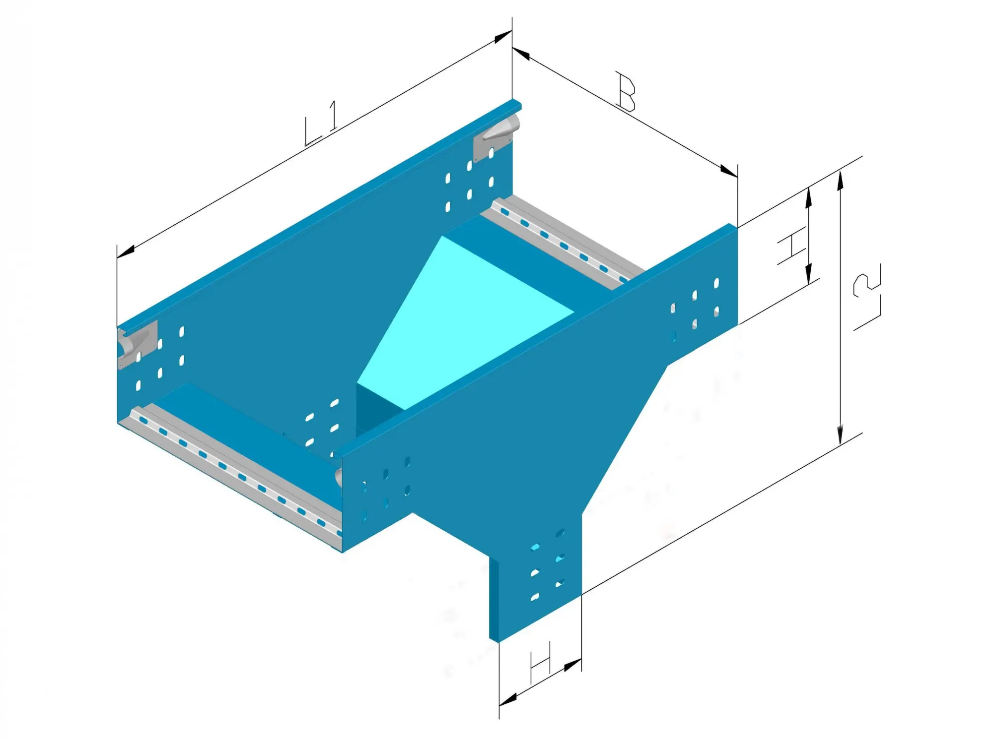
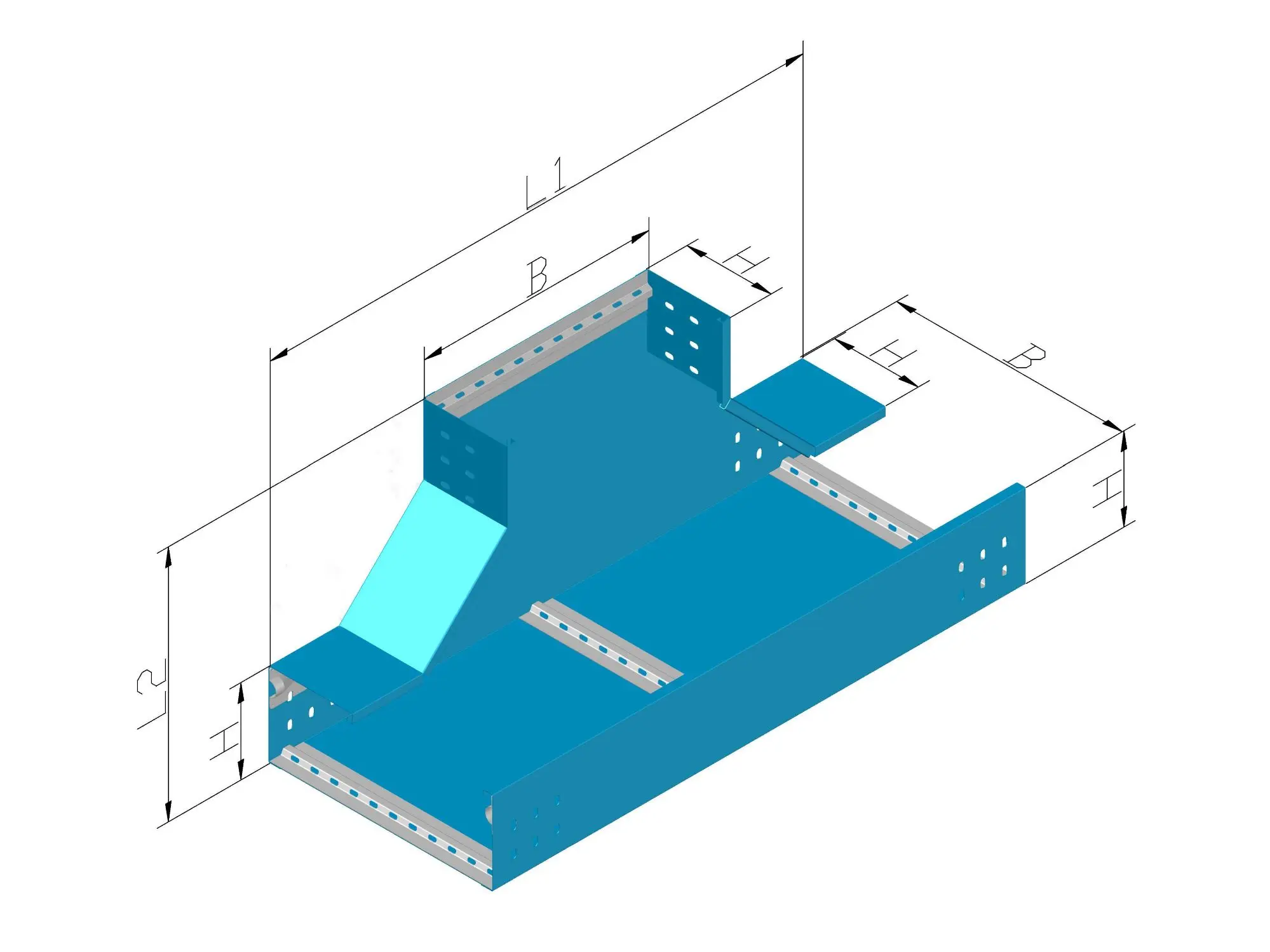
Branch connections for tray runs (equal / entry / corner types).

Crosses

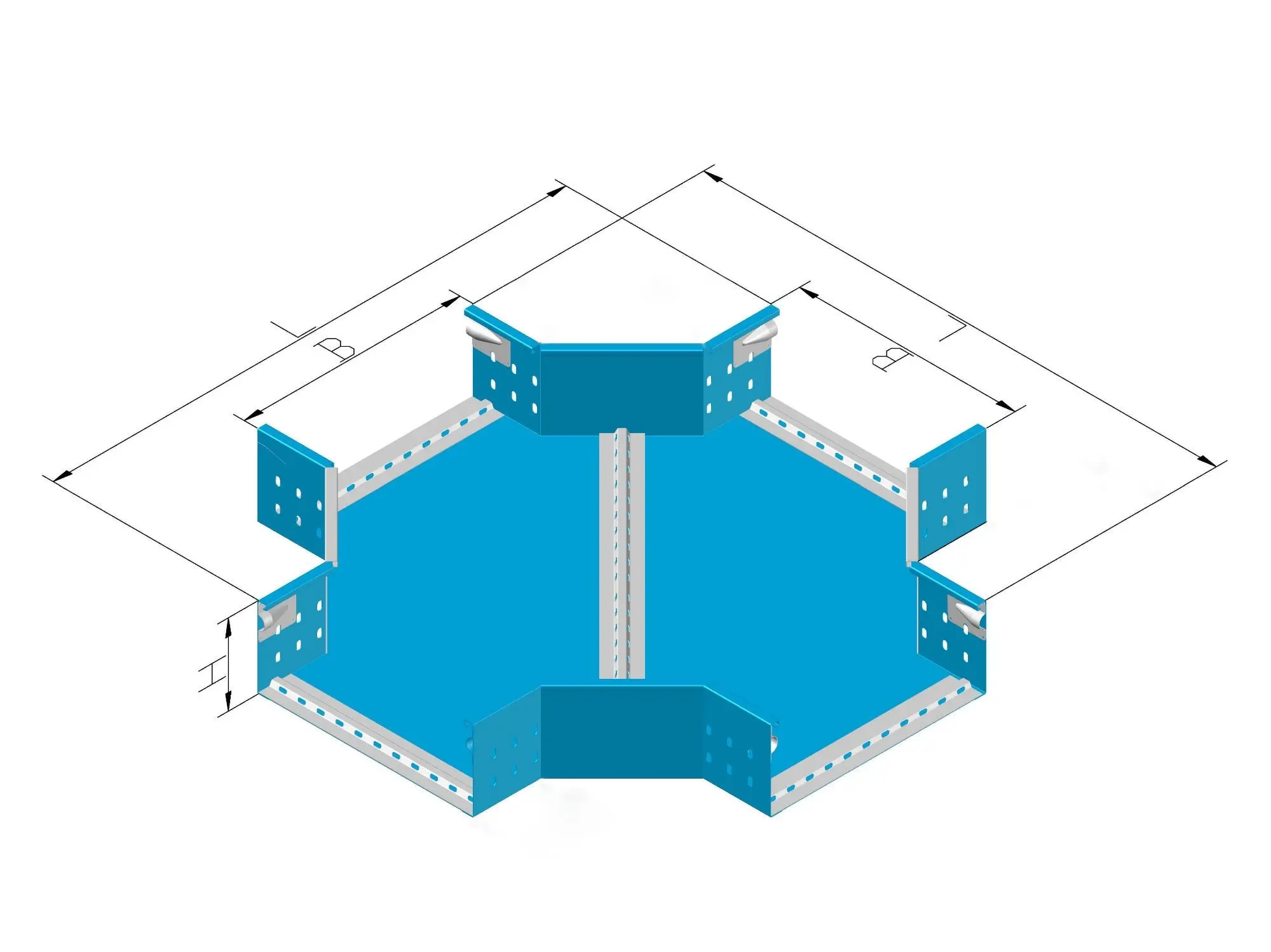
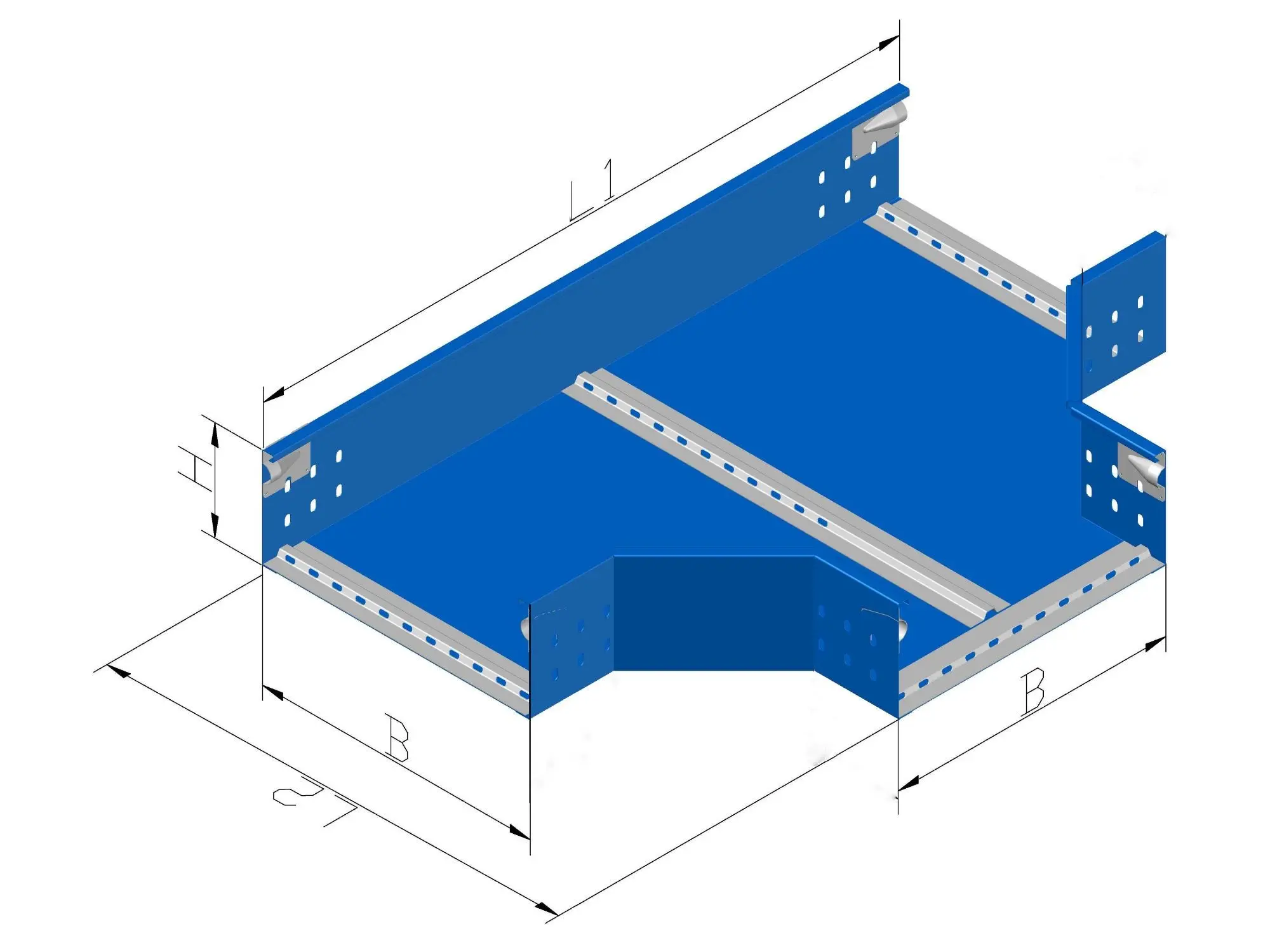
4-way intersections for multi-direction routing layouts.

Elbows

Inside / outside turns with radius options for cable bend control.

Vertical Transitions

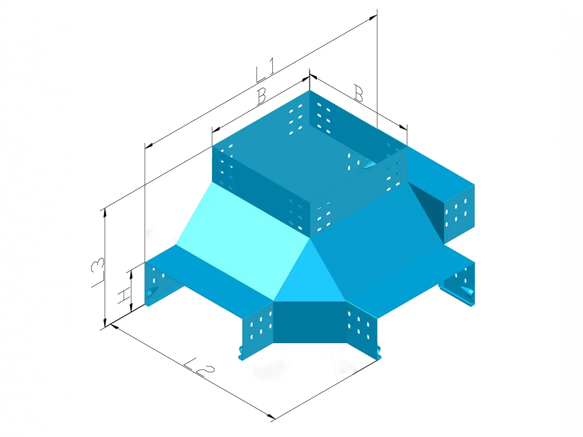
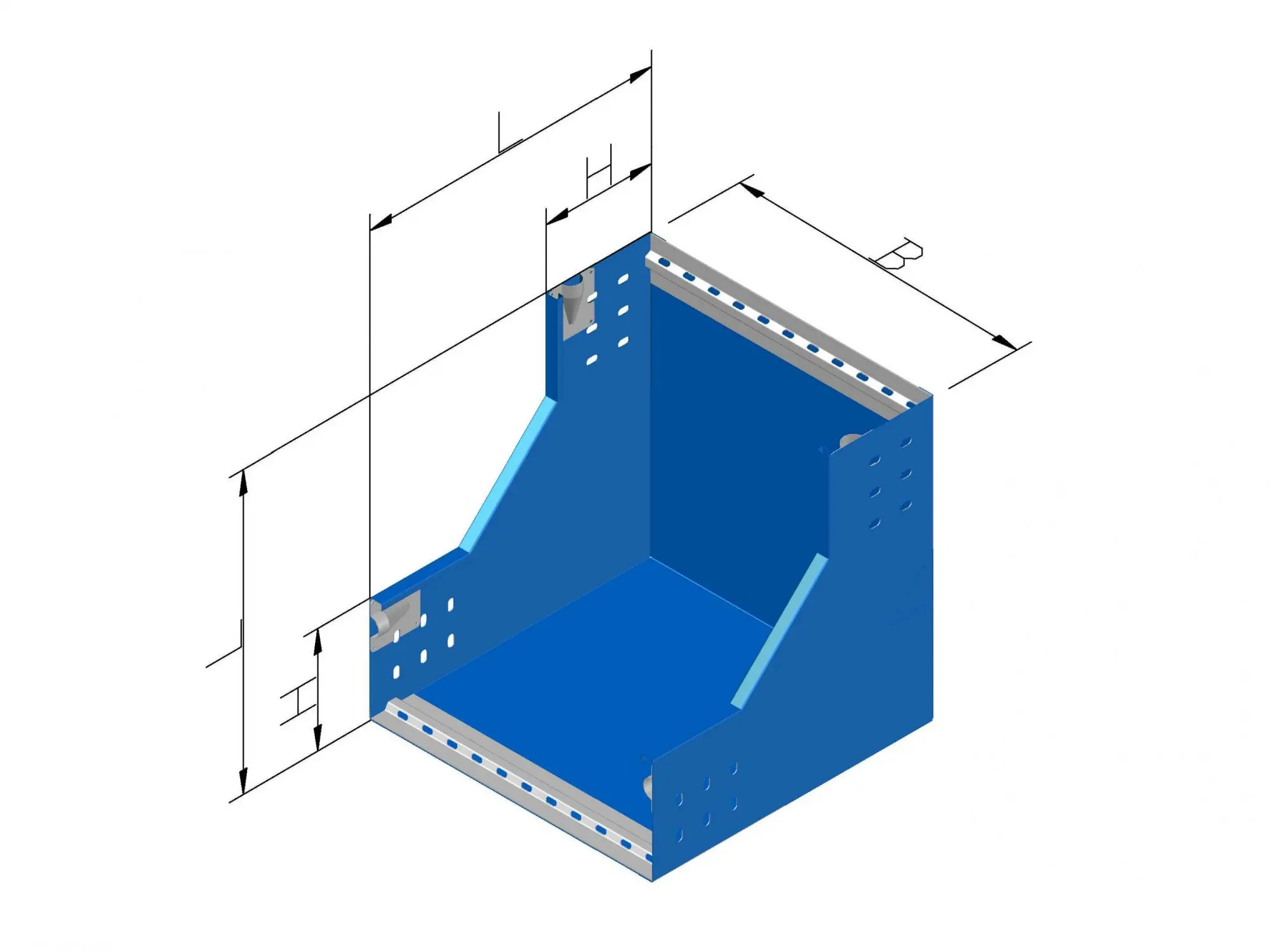
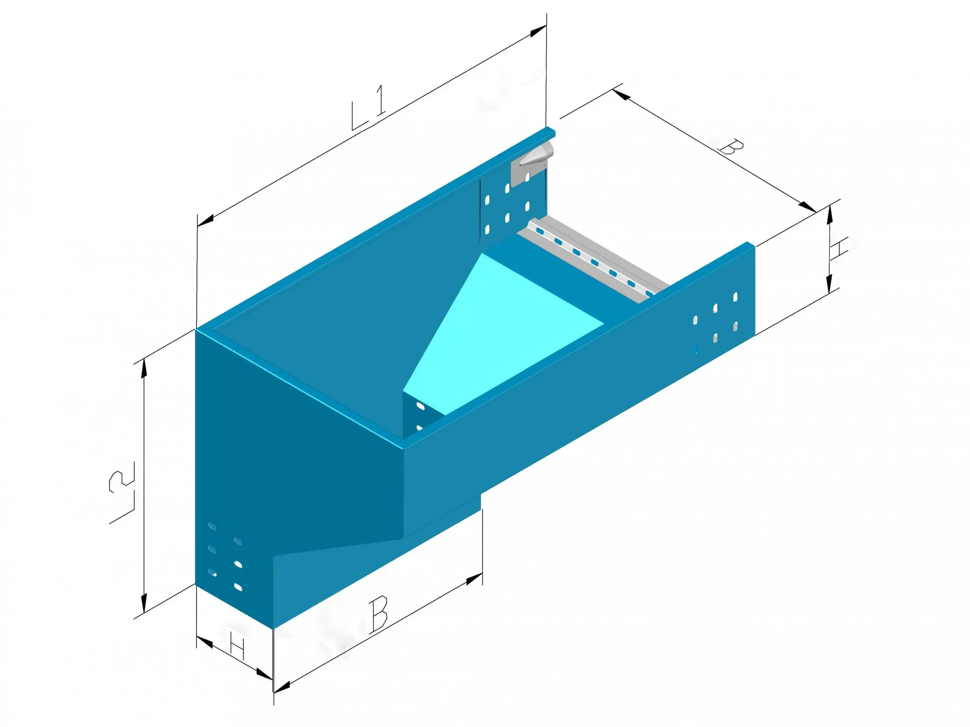
Upward / downward fittings for risers, drops, and elevation changes.

Selection Guide

How to Match Cable Tray Fittings
to Your Tray System

Cable tray fittings are not universal. Cable tray fittings must match your tray profile (width, side-rail height, and pattern) so elbows, tees, reducers, and risers assemble cleanly without field rework. For an accurate takeoff, confirm the inputs below—or send your route drawing and we will map the required cable tray fittings.

TRAY Solid / Perforated / Ladder SIZE Width × Side Height ROUTE Elbow / Tee / Riser Points FINISH G / S / CQ Systems
RUN
TEE
BEND
CABLE TRAY FITTINGS — ROUTE GEOMETRY MAP
1

Route Geometry Fittings

The core cable tray fittings that shape the path: 90°/45° elbows, tees, crosses, reducers, and transitions. They keep turns and branches consistent with your route plan.
FITTINGS ELBOW / TEE
2

Vertical Risers & Drops

When elevation changes are required, cable tray fittings include inside/outside risers, vertical bends, and drop-out/entry points—selected by radius needs and clearance constraints.
RISERS RADIUS
3

Size-Matching Reducers

Reducer cable tray fittings connect different widths or side-rail heights without abrupt offsets. This keeps cable support continuous and improves alignment over long runs.
REDUCER ALIGNMENT
4

Project Matching Checklist

A correct cable tray fittings package is confirmed by tray type, width/side height, finish system, and the exact count of elbows/tees/risers from your layout—so the BOM is clean and procurement-ready.
BOM TAKEOFF
Technical System Fittings

XMQJ Fittings Series

A professional catalog of precision-engineered fittings. Select any item to view its full technical specification table and ordering code guide.

Vertical Downward Tee XQJ-CQ-CE

Vertical Downward Tee (Bottom Entry)

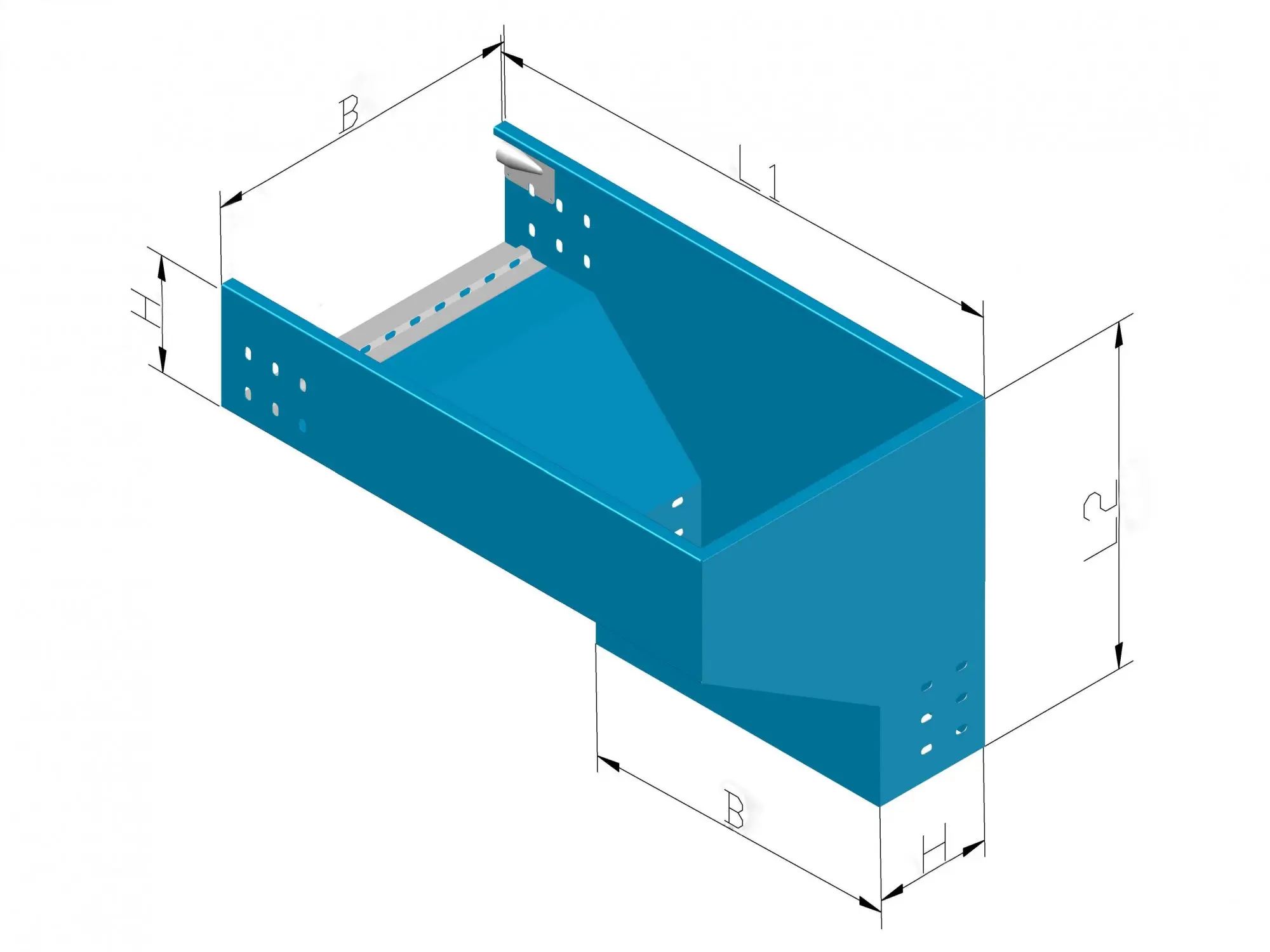
Equal width vertical downward junction for color-coated branch connections.

Vertical Downward Tee XQJ-S-C-03E

Vertical Downward Tee (Equal)

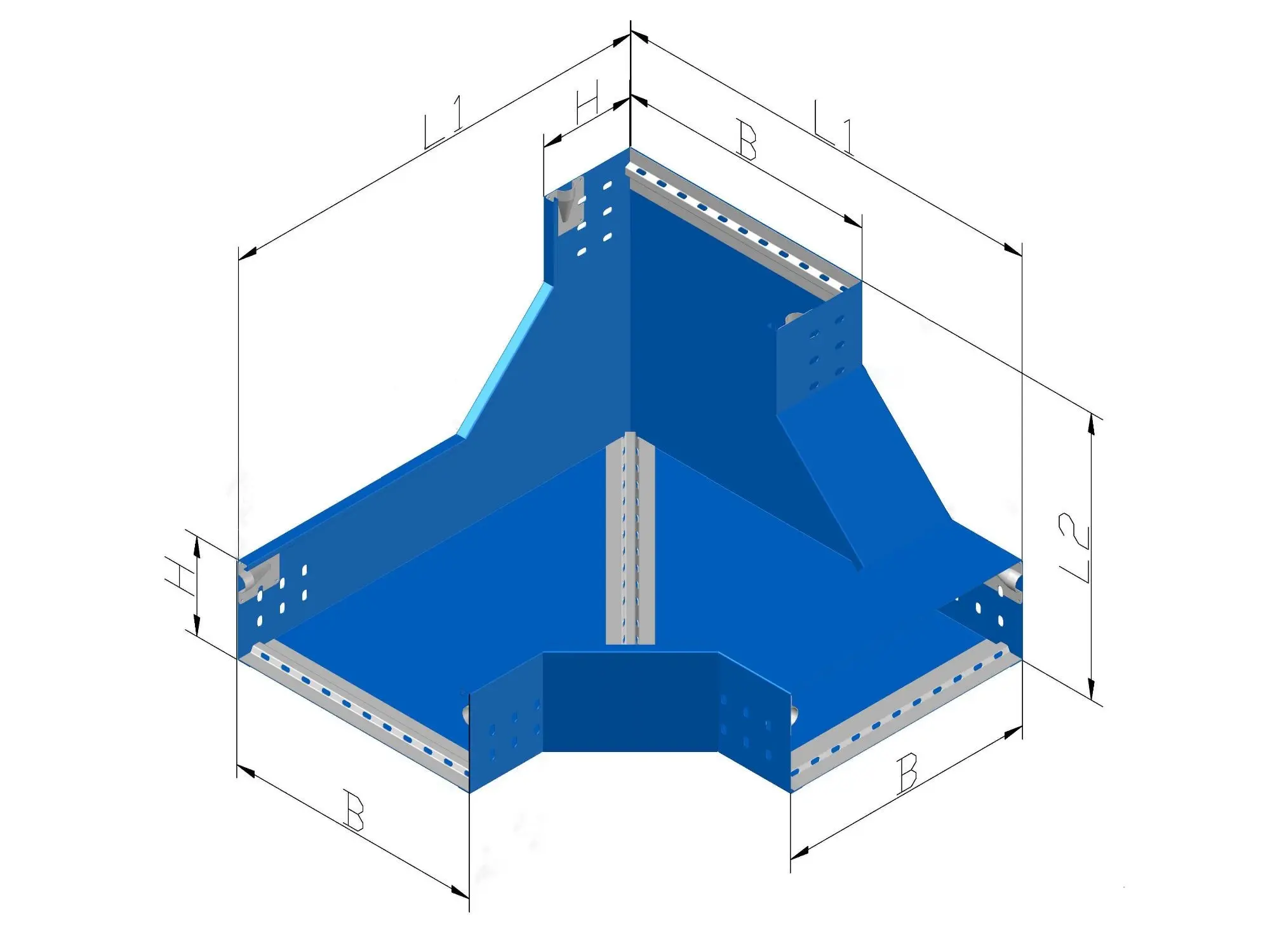
Heavy duty stainless steel downward branch junction.

Vertical Upward Tee XQJ-CQ-C03F

Vertical Upward Tee (Upper Corner)

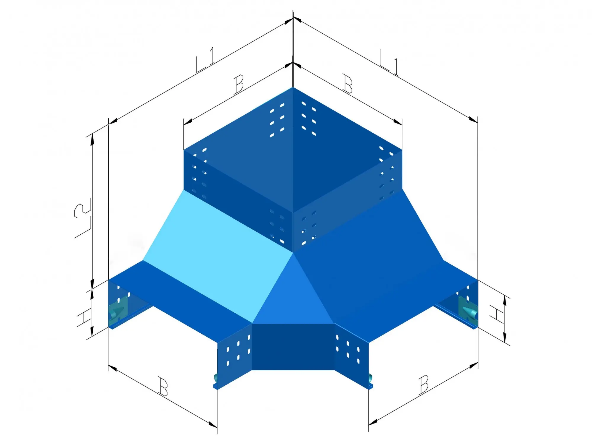
Specialized corner upward junction for elevation shifts in color-coated systems.

Vertical Upward Tee XQJ-S-C-03F

Vertical Upward Tee (Stainless)

Upper corner upward vertical transition made from marine-grade stainless steel.

Vertical Downward Tee XQJ-CQ-C03G

Vertical Downward Tee (Lower Corner)

Bottom corner downward junction designed for branch drops.

Horizontal Cross XQJ-S-C-04A

Horizontal Equal Cross (Stainless)

Four-way multi-directional horizontal intersection for stainless steel trays.

Vertical Downward Tee XQJ-S-C-03G

Vertical Downward Tee (Stainless Lower Corner)

Lower corner branch drop transition piece for high-hygiene environments.

Horizontal Cross XQJ-CQ-C-04A

Horizontal Equal Cross (Coated)

Color-coded 4-way horizontal routing junction for data centers.

Vertical Outside Elbow XQJ-G-C-04B

Vertical Outside Elbow (Equal)

Standard 90-degree galvanized vertical downward elevation change.

Vertical Outside Elbow XQJ-S-C-04B

Vertical Outside Elbow (Stainless)

Premium stainless steel vertical downward transition for industrial use.

Vertical Outside Elbow XQJ-G-C-02C

Vertical Outside Elbow (High Radius)

Large radius downward transition optimized for high-voltage power cables.

Vertical Inside Left Elbow XQJ-G-C-02F

Vertical Inside Left Elbow

Asymmetrical upward vertical turn for complex offset routing requirements.

Vertical Upward Tee XQJ-G-C-02G

Vertical Upward Tee (Standard)

Standard galvanized upward vertical branch intersection component.

Horizontal Tee XQJ-G-C-03A

Horizontal Equal Tee (Galvanized)

Galvanized three-way horizontal intersection for mainstream routing.

Vertical Upward Tee XQJ-G-C-03B

Vertical Upward Tee (Type B)

Equal width galvanized upward vertical branching unit for utilities.

Product Specifications

Engineering Value

Why Choose Cable Tray
Fittings?

Fittings are the routing components that shape a tray run—branching, turning, and elevation changes. A correct fitting set keeps alignment predictable, minimizes on-site rework, and makes project takeoff faster.

01

Geometry-Correct Routing

Build clean pathways with elbows, tees, crosses, and vertical up/down transitions that follow the intended route—without forcing bends or “field hacks”.

02

Profile-Matched Fit (W × H)

Fittings are formed to match tray width and side height, helping bolt patterns, edges, and cover alignment stay consistent across the full run.

03

Finish Consistency (G / S / CQ)

Use the same finish system as your tray line—galvanized, stainless, or color-coated—so corrosion performance stays consistent at every junction.

04

Faster Takeoff & Clear BOM

A defined fitting set makes quoting easier—confirm routing points and quantities quickly, then map each junction to an ordering code for procurement.

Real-World Applications

Where Cable Tray
Fittings Are Used

Fittings are the routing components that change direction, split pathways, or shift elevation. They are selected by tray profile (W × H) and finish system to keep junctions aligned and project-ready.

Cable tray fittings used in industrial plant routing for elbows, tees, crosses, and reducers matched to tray width and side height
01

Junction-Dense Routing Inside Plants

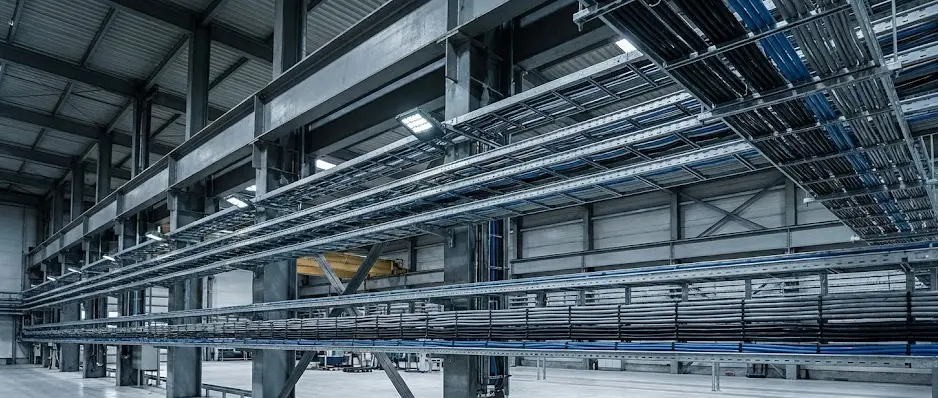
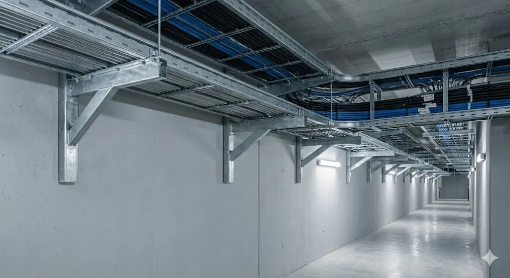
In equipment corridors, tray routes change frequently. Elbows, tees, crosses, and reducers keep branches accurate and avoid misalignment at every junction.

Elbow Tee / Cross Reducer
Cable tray fittings applied on long tray runs for branch points, size transitions, and layout changes using tees, reducers, and horizontal-vertical fittings
02

Long Runs With Branch Points

For main corridors feeding multiple zones, tees and reducers handle branch takeoffs and tray-size changes, keeping the route scalable for commissioning adjustments.

Branch Takeoff Size Change
Cable tray fittings used for elevation changes such as vertical up and vertical down risers, and horizontal to vertical transitions in maintenance corridors
03

Elevation Shifts & Riser Transitions

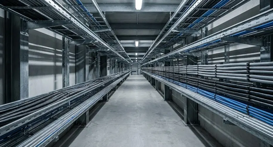
Floor-to-floor routing and maintenance zones often require vertical up/down risers and HV transitions. Correct fitting geometry protects bend radius control and route continuity.

Vertical Up Vertical Down HV Transition
Cable tray fittings for outdoor routing where elbows, tees, and risers require finish matching such as galvanized, stainless, or color-coated systems
04

Outdoor Routes With Finish Matching

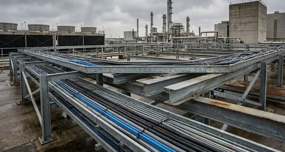
Exposed routes amplify corrosion risk at junctions. Specify fittings in the same finish system as the tray line to keep protection consistent throughout the run.

G / S / CQ Outdoor Ready
Engineering Specification

How Cable Tray Fittings
Are Specified

Cable tray fittings are specified to maintain route geometry, junction alignment, and field-assembly consistency—so elbows, tees, crosses, reducers, and vertical transitions match your tray profile.

Note: Fittings are the parts that change route or elevation. Items that do not change geometry (accessories/hardware) are specified separately.

Information Required

To confirm fitting compatibility and create a project-ready route takeoff, these inputs are typically reviewed:

  • Tray profile: tray type/series + section size (Width × Side Height) to match fitting geometry.
  • Junction map: where the run turns, branches, crosses, reduces, or terminates (plan view).
  • Elevation changes: vertical up/down points and horizontal-to-vertical transition requirements (riser style).
  • Transition preference: standard vs sweep radius; reducer direction; inside/outside riser orientation.
  • Material & finish system: galvanized / stainless / color-coated (keeps corrosion performance consistent at junctions).
  • Connection standard: hole pattern reference, splice style, and any tolerance constraints for field assembly.
Engineering note: Fit is governed by W × H profile + junction geometry. When those match, alignment stays predictable and field assembly avoids cutting, drilling, and rework.

What Is Delivered

After confirming project conditions, fittings are supplied as a coordinated routing set:

  • Fitting list matched to tray size: elbows, tees, crosses, reducers, end closures, and transition pieces.
  • Vertical routing package: vertical up/down risers and HV transitions for floor-to-floor or equipment platform changes.
  • Connection confirmation: hole pattern reference, joint approach, and assembly notes to reduce site uncertainty.
  • Project-based BOM: quantities mapped by junction points (ready for procurement and site planning).
  • Drawings / labeling guidance: fitting identification, packing marks, and route reference for fast receiving & installation.
Why this matters: A complete routing fittings set keeps every turn/branch/transition consistent with the layout— so the tray pathway is built as designed, with fewer surprises on site.

Ready to Confirm Your
Cable Tray Fittings Takeoff?

Send your tray profile (type, width × side height) and route junction points. We’ll confirm compatible fittings that shape the run—including elbows, tees, crosses, reducers, and vertical up/down transitions— and return a project-ready BOM for fast field assembly.

Note: Fittings are the parts that change route geometry. Non-geometry items are handled on a separate page.

Common Questions

FAQ for Cable Tray
Fittings

For tray types, materials, finishes, and system selection basics, please see our Cable Tray Systems pillar page.

For code compliance references, you can also review NFPA 70 (NEC).

What is a cable tray fitting?
A cable tray fitting is a formed component that changes the tray run geometry—such as elbows (horizontal bends), tees/crosses (branches), reducers (width transitions), and vertical risers (elevation changes). Fittings are selected by tray width, side-rail height, and the required route direction/radius so the system assembles cleanly without field improvisation.
What are the most common types of cable tray fittings?
The most common fitting families include: horizontal elbows (90°/45°), horizontal tees, crosses, reducers, vertical inside/outside risers (up/down), and drop-out/exit fittings where controlled cable exits are needed. Most projects standardize these families so route changes remain consistent across the entire tray network.
What is a cable tray coupler?
A coupler (often referred to as splice plates) is the joining part used to connect straight tray sections—or to connect fittings to straight sections—while maintaining alignment and joint strength. Couplers are matched to the tray’s side-rail geometry and hole pattern to keep assembly predictable and rigid.
How do I choose an elbow, tee, or cross fitting?
Start with your route layout: elbows for turns, tees for one branch, crosses for two branches. Then confirm tray width and side-rail height, and specify the preferred bend style (standard vs sweep radius). If the branch width differs from the main run, combine the tee/cross with a transition/reducer.
What is the difference between a reducer and a transition fitting?
In tray work, both terms are used for fittings that change tray width. A reducer typically refers to a width change between two sizes, while “transition” may also describe the specific shape (straight taper vs offset) used to manage clearance, cable bending, or alignment requirements. The correct choice depends on space constraints and how cables enter/exit the changed section.
Inside riser vs outside riser—what’s the difference?
Both are vertical fittings used to change elevation. The difference is where the bend is formed relative to the tray side rails. Inside vs outside risers are selected to suit clearance, mounting constraints, and how you want the tray line to “track” along walls/columns or overhead structures. If you share the elevation change direction and nearby obstacles, the correct riser style becomes straightforward.
What is a sweep radius cable tray elbow?
A sweep radius elbow uses a larger bend radius than a standard elbow. It is often preferred when cable bend control matters (thicker power cables, dense fills, or easier pulling requirements). Sweep elbows typically reduce pulling stress and make cable routing smoother through corners.
How do you attach cable tray fittings to strut/supports?
Fittings are supported using the same project support method as the tray run (wall brackets, trapeze hangers, channel strut interfaces, etc.), but special attention is given near bends/branches where load paths change. Confirming tray size, support type, and spacing constraints helps select the correct mounting interface so the fitting remains stable and aligned during installation and service.
Do I have to put a bonding jumper on a cable tray?
It depends on the project’s electrical continuity requirements and how continuity is maintained across joints (coatings and joint design can affect continuity). Many projects specify bonding measures at joints, expansion locations, or where continuity cannot be guaranteed by mechanical connections alone. The final requirement should follow the governing installation standard and the site’s engineering notes/AHJ requirements.
Are fittings the same as accessories or hardware?
No. Fittings are the components that change route geometry (tee/cross/elbow/vertical up/down transitions, reducers). Accessories/hardware typically do not change route geometry—those items are used for joining, retention, or mounting. Keeping the two categories separate helps BOM confirmation stay clean and prevents ordering mismatched parts.