Cable Tray Width Explained: Core Definition and Direct Answer
Cable tray width is the clear internal span available for cable routing, typically 100–900 mm for ladder, wire mesh, and perforated cable trays. In engineering design, you size width from calculated cable fill (usually 40–60 % of usable area) plus defined future capacity, then verify that the combined tray + cable load and midspan deflection remain within IEC 61537 or NEMA VE 1 load class limits.
Cable tray is one part of the wider cable management system that includes supports, fittings, and in some projects, busway systems sharing the same racks. Getting width right avoids rework later when you coordinate with structure, HVAC, and maintenance access.
How Cable Fill, Future Capacity, and Width Work Together
Cable tray width, cable fill ratio, and future capacity are a three‑way trade. If you increase width without revisiting fill and loading, you can trigger structural penalties or thermal derating that only appear during detailed checks.
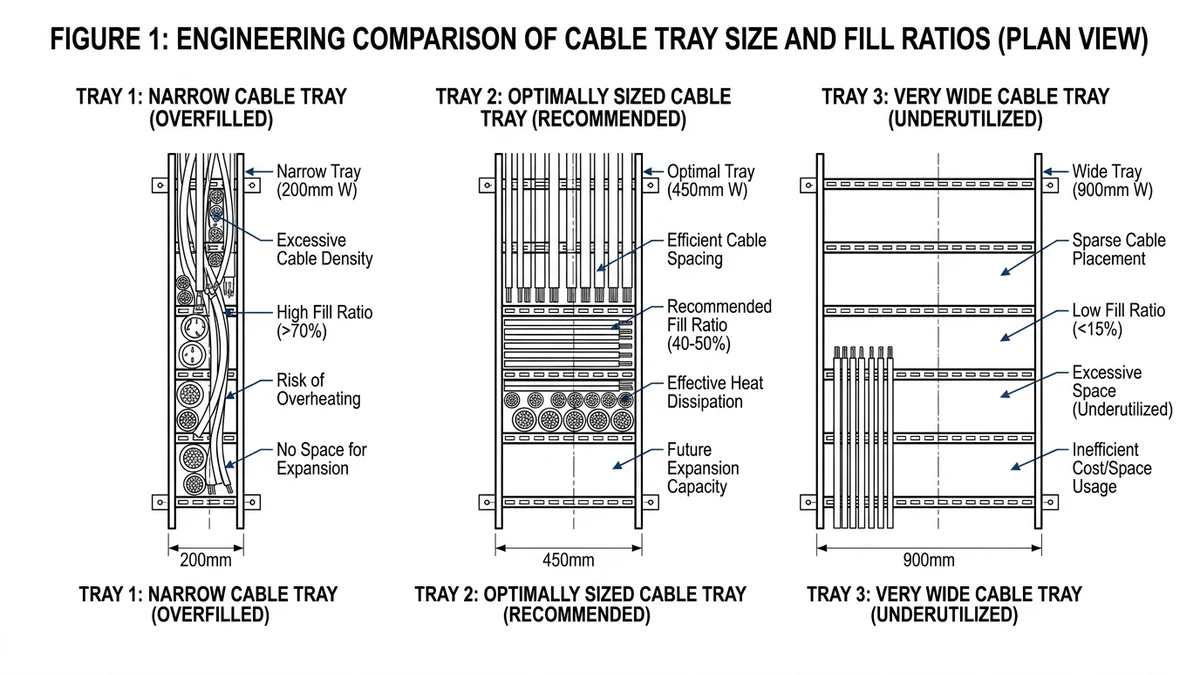
Fill Ratio as the Governing Parameter
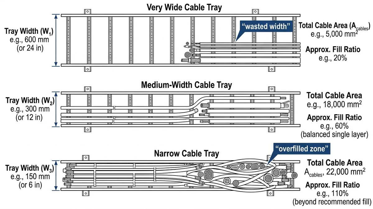
Fill ratio is the percentage of the tray’s usable cross‑section occupied by cable:
fill ratio = (sum of cable cross‑sectional areas) ÷ (tray internal width × assumed cable depth)
For ladder cable tray and wire tray, designers normally use plan area with an assumed cable depth of one to two cable diameters, depending on whether stacking is allowed.
Typical working ranges for power and control cables:
Design fill: 40–60 % of usable tray area
Initial install target: 30–40 %
Reserved future capacity: 20–30 % (within the same total 60 % limit)
Example: A 300 mm ladder cable tray carrying 1‑core 240 mm² cables (≈35 mm outside diameter) will typically reach ~50 % fill at around 6–8 cables in a single layer, depending on spacing and whether you allow some positional overlap.
Above roughly 60–70 % fill, two key effects appear:
Heat dissipation worsens → ampacity derating increases, which can extend fault clearance times and may require upsizing conductors.
Cable pulling forces rise → sidewall pressure increases in bends and verticals, raising the risk of outer sheath damage.
Future capacity is not “fill it to 100 % someday”; it is the margin that keeps ampacity, thermal limits, and structural loading within specified standards over the system’s life.
Why “Bigger Tray” Is Not a Free Upgrade
Upsizing from 300 mm to 600 mm width roughly doubles usable area, but it also changes the mechanics:
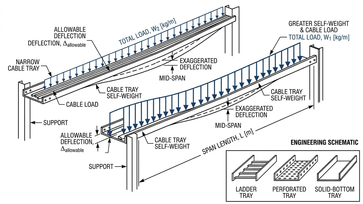
Self‑weight: Typically increases by 20–60 % depending on side‑rail height and thickness.
Deflection: For a given span and uniformly distributed load, a 600 mm ladder cable tray will often deflect roughly twice as much as a 300 mm tray of the same profile.
Support spacing: To stay within L/200–L/300 deflection limits in IEC 61537, support spans for 800–1000 mm cable trays may need to be reduced from 3.0 m to 2.0–2.5 m.
In field deployments, we repeatedly see oversized trays installed “for future growth” that then require closer hanger spacing, heavier supports, and more complex seismic bracing than a pair of narrower trays sharing the same load.
Design Takeaway
Start from the cable schedule and thermal design:
Calculate cable areas and groupings.
Select a preliminary width that yields ≤50–60 % fill at end‑of‑life cable loading.
Compute tray load in kg/m (cables + tray + covers where applicable).
Check structural class and deflection against IEC 61537 / NEMA VE 1 and your support span.
Only increase width if both structural and thermal checks remain acceptable.
Bigger width only helps when it reduces fill without breaching load class or deflection limits—and when you can physically route it through the structure.
[Expert Insight]
– In our load testing, the most common non‑compliance is not overfill; it is deflection on wide trays specified at “standard” 3.0 m spans.
– Maintenance teams often report that trays run closer to design fill within 3–5 years, so designing for 30–40 % initial fill is usually more realistic than 20 %.
Structural and Thermal Trade‑Offs of Wider Cable Trays
Wider cable trays change both the structural behavior of the support system and the thermal environment around cables. Beyond roughly 400–600 mm width, stiffness loss and thermal crowding become visible enough that you should recheck assumptions rather than simply scaling up from a smaller tray.
Structural Behavior: Deflection and Vibration
For a given material and side‑rail profile, increasing width reduces transverse stiffness. Consider a steel ladder tray with identical rails and rungs:
At 300 mm width and 3.0 m span, deflection under a 75 kg/m uniformly distributed load may be around 5 mm.
At 600 mm width with the same span and load, deflection can increase to 10–12 mm.
At 900 mm width, deflection can reach 15 mm or more, potentially exceeding your L/200 limit for a 3.0 m span.
Since bending stress depends on load (w), span (L), and section modulus (Z), maintaining safe stress and deflection on wide trays usually requires either:
Reducing support span (e.g., 3.0 m → 2.0–2.5 m), or
Upgrading to a deeper or heavier rail section.
Dynamic effects matter as well. Seismic accelerations or a technician stepping on a wide tray generate higher vibration amplitudes when stiffness is marginal. That can fatigue fixings, distort splice plates, or overstress hangers.
Engineering implication: treat any tray ≥600 mm as a different structural category. Re‑check spans, hanger sizes, and bracing assumptions instead of copying details from 300–400 mm runs.
Thermal Behavior: Heat Dissipation and Ampacity
Thermally, width by itself is not beneficial or harmful; the combination of width and fill controls cable temperatures.
When fill ratio stays below ~40 %, wider trays can improve air circulation between cables if they are spread out. Once fill climbs above ~40–50 % of area:
The central region of the tray sees lower airflow.
Mutual heating between parallel power cables increases.
Multi‑layer stacking, common in wide trays, reduces both natural convection and radiation.
For LV power cables with 70–90 °C conductor ratings, practical observations and manufacturer data typically show:
A tightly packed 900 mm ladder tray can require 10–25 % ampacity derating relative to the same cables spread across two loosely filled 300–400 mm trays.
Stacked layers on wide trays can raise visible cable surface temperatures by 5–10 °C at the same load compared with single‑layer arrangements.
If you are running cables near their thermal limits, this can push you into larger conductor sizes or lower protective device settings.
Design consequence: don’t treat width as a cooling strategy. Verify ampacity with the actual width, fill pattern, and ambient temperature using manufacturer tables or IEC 60364‑5‑52 guidance at minimum, and be prepared to split runs when widths exceed about 600 mm.
[Expert Insight]
– In several industrial runs we reviewed, splitting one 900 mm tray into two 450 mm trays reduced calculated derating enough to keep the original cable sizes, offsetting the added hardware cost.
– Thermal imaging on heavily loaded wide trays often shows a 5–8 °C hotspot difference between outer and inner cable rows, especially where trays pass near warm process equipment.
Applying Width Choices to Real Routes and Site Constraints
Cable tray width selection becomes practical when you overlay it on walls, beams, pipe racks, and access paths. The electrically “ideal” width sometimes loses to the one that actually fits through openings, preserves egress, and can be supported efficiently.
Routing Through Crowded Corridors
In plant corridors or tunnels only 800–900 mm wide, a 600 mm cable ladder with side rails can leave less than 150 mm clearance to walls or handrails. On drawings this may “fit,” but in operation it constrains walking space, ladder placement, and lifting access.
A pragmatic pattern that works in many facilities:
Above about 2.2 m elevation: use 400 mm trays and stack two or three tiers rather than one 800–900 mm tray.
Below about 2.2 m: keep widths to 300–400 mm to maintain comfortable egress, even if it means adding an extra run.
Use when: long straight corridors with repeated access points and frequent maintenance traffic.
Avoid when: you have heavy busduct or very large power cables better served by busway or dedicated supports.
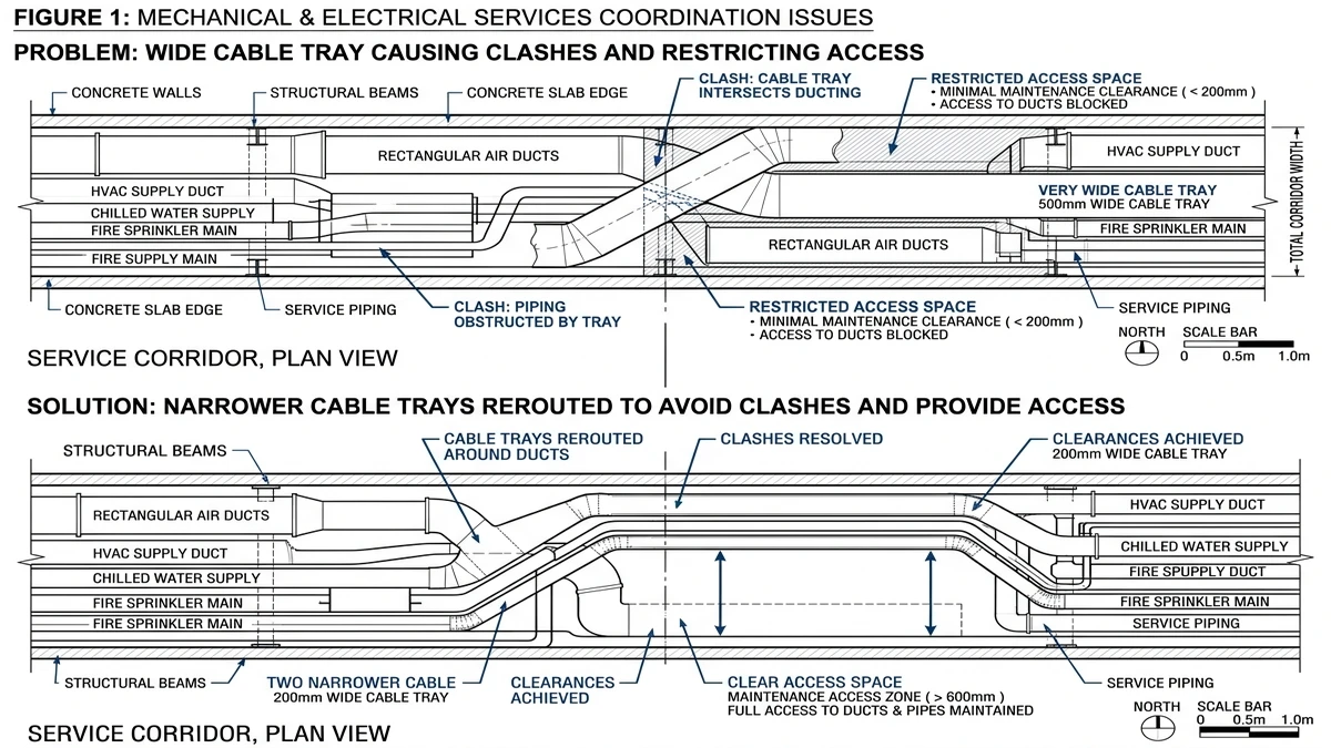
Navigating Structure, HVAC, and Pipework
Beams at 3.0 m centers, large ducts, and dense pipe racks often dictate your maximum practical tray width more than the cable count does. A 600 mm tray may not pass cleanly between services where only 450 mm gaps exist.
A field‑tested workflow:
Model the primary structure, HVAC, and pipework in 2D/3D.
Route “envelopes” for 300, 400, and 600 mm trays with candidate support spans (e.g., 2.5–3.0 m).
For each segment, select the smallest width that meets fill and load class while passing through openings and around clashes.
Result: mixed widths—600 mm on unobstructed pipe racks, 300–400 mm where the route weaves through congested ceiling spaces or wall penetrations.
If you expect frequent changes or additions, consider how easily you can mount additional trays or cable tray accessories to existing steelwork without rework.
Example: Substation to MCC Room Route
Suppose you must route 12 cables over 45 m from a substation to an MCC room:
3 × 1‑core 240 mm² LV power cables
9 × control / instrumentation cables
Step‑by‑step design:
Calculate total area and select a preliminary tray width: a 500–600 mm ladder tray might give ~35–45 % initial fill, allowing for two more power circuits in future.
Outdoor pipe rack section: space is open with supports at 3.0 m. The 500–600 mm width is acceptable, provided the structural load class and deflection are within the selected IEC 61537 category.
Through a 1.0 m wall penetration and congested ceiling: the same 600 mm tray conflicts with ducts and fire dampers. Splitting into two 300 mm trays stacked vertically passes through existing openings, avoids major clash modifications, and improves separation between power and control cables.
Use when: different segments have very different spatial constraints.
Check before specifying: whether splitting into multiple narrower trays affects your fire‑stopping details, support loads, and maintenance access sequence.
How Xinma Helps Coordinate Width, Loading, and Support Decisions in Specifications
Xinma approaches cable tray width, structural loading, and support layout as a single coordinated design problem. That coordination is increasingly important as tray systems share racks with other equipment like busway or process pipework.
From the discussion so far, several engineering consequences are clear:
A 300 mm tray at 3.0 m span and 80 kg/m behaves very differently from a 600 mm tray at the same span and load—deflection and natural frequency both change.
Increasing tray width without revisiting span and support type can push deflection beyond L/200, even when the catalog load class seems adequate.
Fill ratio and cable mix control both thermal derating and mechanical kg/m load, so ampacity and structural checks must be done together.
Fittings, splice plates, covers, and seismic bracing often become the weak link if they are sized only for nominal width without accounting for real loads and future cables.
Where Xinma’s Engineering Support Matters
Xinma can support specifiers and designers through:
Load class and span verification
Checking candidate widths against specified load classes (e.g., 100–200 kg/m) and planned spans (2.0–3.5 m), and advising when you should either shorten spans or move to a higher‑capacity profile or ladder cable tray design.
Thermal and mass coordination
Reviewing cable schedules to combine cable mass, fill, and ambient temperature, ensuring chosen widths keep both structural utilization and thermal derating within acceptable ranges.
Fittings and accessories alignment
Making sure elbows, tees, reducers, covers, and cable tray fittings are rated for the same load and environmental conditions as the straight tray sections, including any extra weight from snow, dust, or insulation.
Support and bracing optimization
Suggesting support span adjustments, hanger selections, and, where needed, seismic bracing layouts when calculations show that wide or heavily loaded trays approach deflection or vibration limits.
In projects we have reviewed, combining these checks early in design typically reduces late changes to support steel and minimizes site‑level decisions based on “what fits” rather than what meets the design load class.
If you want cable tray width, supports, and loading to be validated as a coordinated system rather than as isolated catalog items, Xinma can work from your 2D/3D layouts, cable schedules, and specifications to propose a consolidated tray schedule and support scheme. For background on typical tray types and applications, you can also refer to industry guidance such as IEC 61537 for cable tray systems (see the IEC webstore: IEC 61537 publication page) and Xinma’s own overview of what cable tray systems are used for.
This article has been updated with explicit source and procurement checks so engineering, EPC, and purchasing teams can verify the recommendations instead of relying only on generic product descriptions. For project use, treat the table below as a starting evidence map and confirm the final requirements against local codes, consultant drawings, and supplier submittals.
Use this source to verify standards, product scope, installation assumptions, or supplier evidence before final specification.
Buyer Verification Checklist
Request drawings that show tray width, depth, side rail profile, bend radius, fittings, and support spacing.
Ask for load tables or engineering assumptions that state test span, load class, and deflection criteria.
Confirm material grade, surface finish, coating method, and corrosion exposure assumptions before comparing prices.
Check whether accessories such as covers, couplers, reducers, clamps, grounding jumpers, and brackets are included.
For EPC or export orders, review packaging, labeling, inspection records, and drawing revision control before shipment.
Frequently Asked Questions
How do I choose cable tray width from a cable schedule?
Add the cross‑sectional areas of all cables expected at end‑of‑life loading, divide by an assumed packing depth (often 1.5–2 cable diameters), then pick a tray width that keeps working fill within about 40–60 % while still meeting the required load class and support span.
When should I split one wide cable tray into two narrower runs?
Consider splitting when a single tray above about 600 mm would cause excessive deflection on planned spans, clash with structure or services, or force ampacity derating that could be avoided by using two narrower trays at lower fill.
Does a wider cable tray always reduce cable temperature?
No, a wider tray only helps thermally if the same cable set is spread out at a lower fill ratio; when extra width is used to add more cables or layers, inner cables may actually run hotter due to reduced airflow and increased mutual heating.
What span should I use for a 600 mm cable ladder?
Span selection depends on load class and section rigidity, but many designers reduce spans to around 2.0–2.5 m for 600 mm trays carrying 75–150 kg/m to keep deflection within commonly used L/200–L/300 limits and maintain reasonable vibration behavior.
How do structural load classes for cable tray relate to cable weight?
Structural load classes specify the maximum uniformly distributed load the tray and supports can carry at a given span, so you must sum the weight of cables, tray, fittings, and covers in kg/m and confirm that this total stays within the selected class with an allowance for future cables.
Where can I find typical dimensions and ranges for standard cable tray widths?
Manufacturers usually publish dimension tables, and summary guides such as Xinma’s references on common cable tray dimensions can help you map nominal widths and heights to practical fill and support strategies for different applications.
Kevin Zheng
Kevin Zheng is a manager linked to Shanghai Xinma Busway & Cable Tray Co., Ltd. He writes technical content on cable tray systems, installation practice, sizing logic, load classes, and related standards for industrial and infrastructure applications.