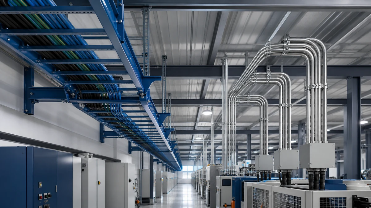
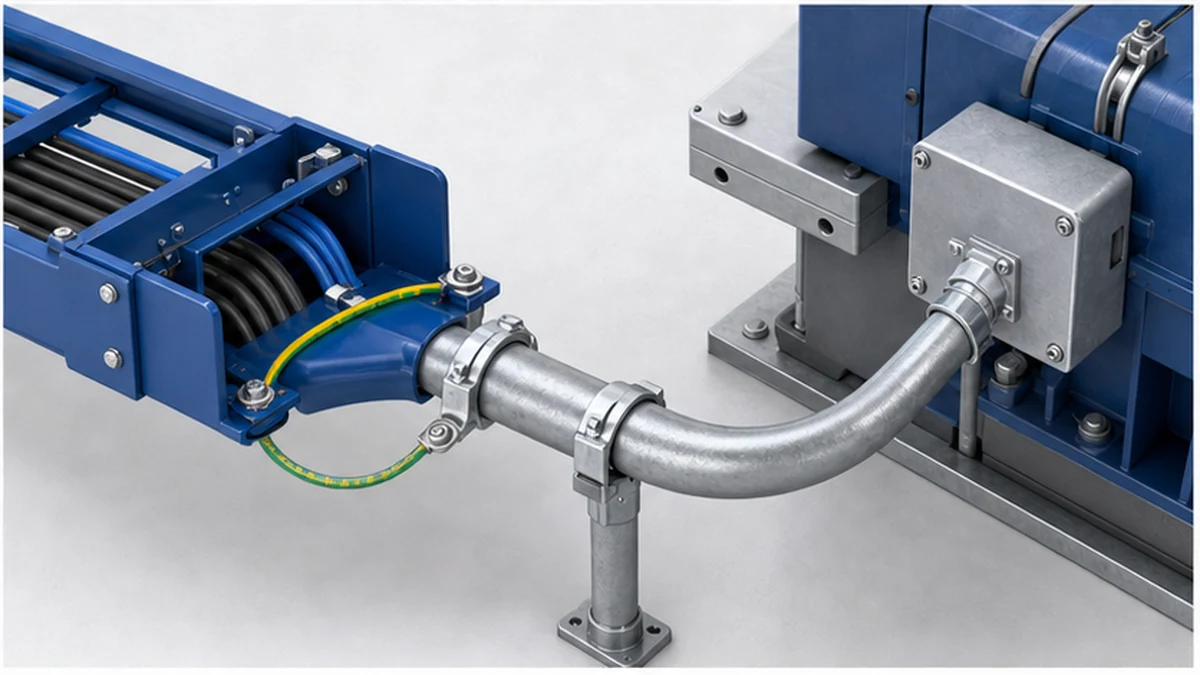
Cable tray and conduit solve different routing problems. Cable tray is usually the better main route for long runs with many power, control, or data cables. Conduit is usually the better final route where conductors need an enclosed path, stronger mechanical protection, or a code-required sealing method. The practical answer is often a hybrid system, not an all-tray or all-conduit decision.
For an early design decision, start with the cable count, route length, exposure to impact, expected future additions, and the local electrical code. The Xinma cable tray range is designed for the main support portion of this workflow, with compatible fittings, supports, covers, and bracing interfaces considered before procurement.
What Cable Tray and Conduit Are Designed to Do
Cable tray is an open or semi-enclosed structural support system. It carries cable runs along ceilings, racks, walls, or service corridors. Installers can see the cables, inspect their condition, add circuits, and remove abandoned cable without reopening the pathway.
Conduit is a tubular raceway through which individual conductors or cables are pulled. Rigid metal, intermediate metal, electrical metallic tubing, PVC, and flexible types serve different environments. The enclosure gives a defined degree of mechanical and environmental protection, while metallic conduit can provide an equipment-grounding path when the applicable code permits and the installation is continuous.
Neither route should be selected from a catalogue image. A tray route must be checked for cable weight, support span, fill, bonding, cover needs, and access. A conduit route must be checked for conductor fill, bends, pulling access, support, corrosion exposure, and any required seals.
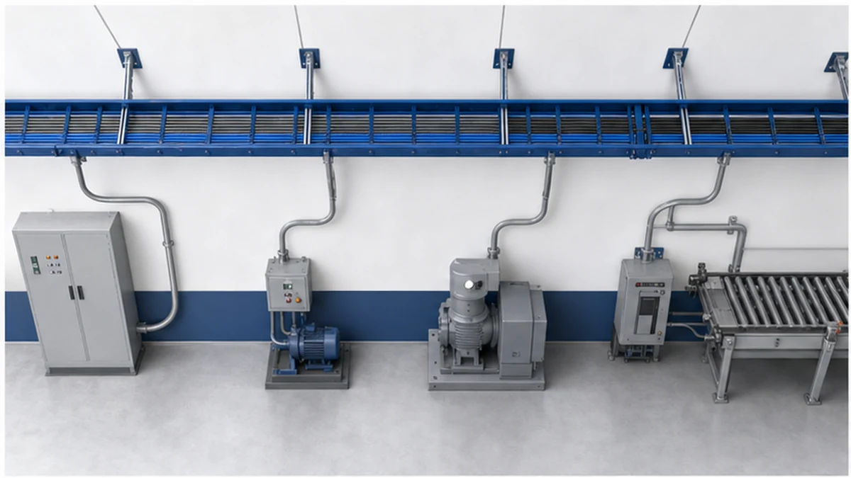
Compare a shared overhead tray route with protected conduit drops.
Cable Tray vs Conduit: The Decision Table
Design factor
Cable tray usually fits when
Conduit usually fits when
Cable quantity
Many circuits share a common corridor
One circuit or a small group follows a short route
Mechanical protection
The route is overhead or otherwise protected from impact
Equipment drops, exposed walls, traffic zones, or areas prone to impact
Heat and grouping
Power cables benefit from open-air spacing and inspection
The enclosure and conductor grouping have been calculated for the local rules
Future changes
The project expects additions, rerouting, or frequent maintenance
The route is stable and unlikely to change
Installation geometry
Long horizontal distribution routes
Short point-to-point routes, vertical drops, and equipment connections
Environmental control
The selected tray material, cover, and cable jacket suit the exposure
A closed raceway or specific sealing method is required
The table is a starting point, not a substitute for the authority having jurisdiction, electrical engineer, or project specification. Hazardous locations, fire-rated penetrations, underground sections, and public-facing spaces can introduce requirements that change the choice.
Where Cable Tray Has the Stronger Case
Cable tray normally earns its place on long shared routes. A single support system can carry multiple cables with accessible spacing, so it is easier to inspect cable identification, route segregation, and visible damage. It also gives project teams room to plan spare capacity without installing a separate raceway for every future circuit.
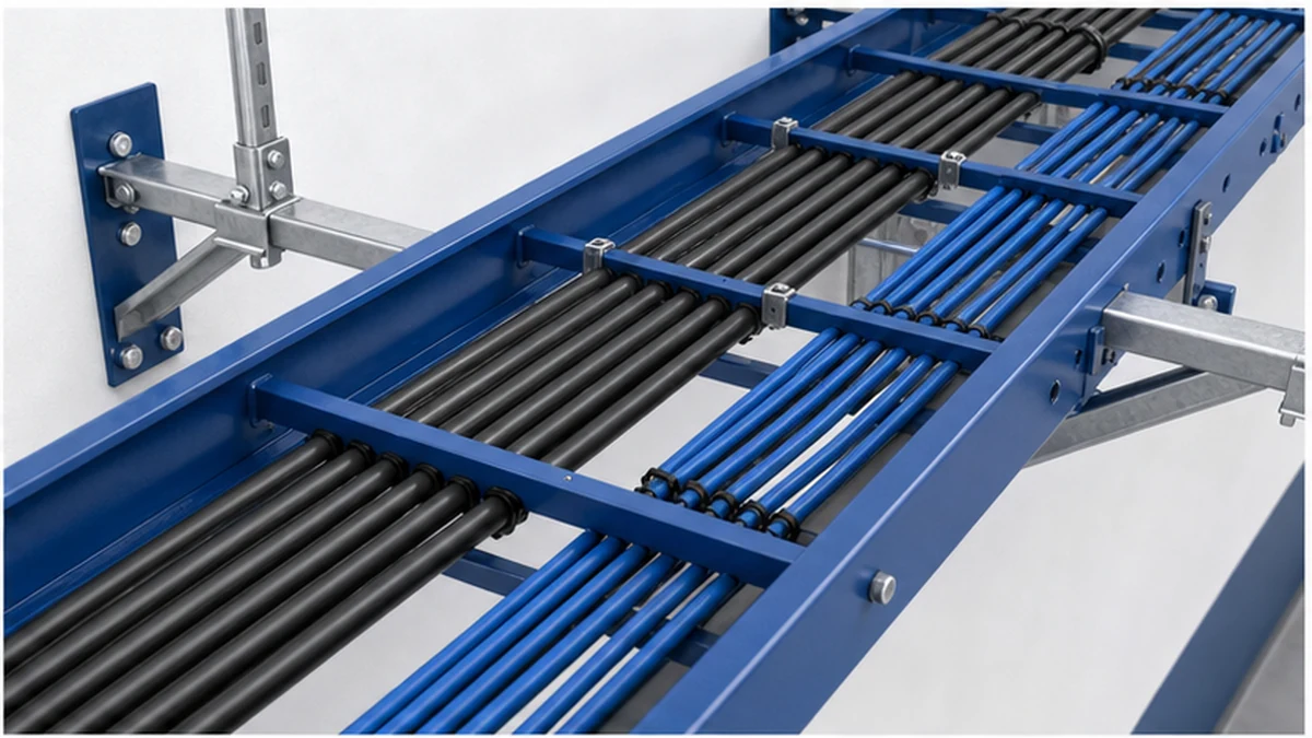
Open ladder construction is often used for heavier power cable groups because it supports the cable weight while allowing airflow around the cables. Where containment, smaller cables, or a more protected route is needed, a perforated or solid-bottom system may be more appropriate. The product choice still needs a load and span check; the ladder cable tray product page is useful for reviewing the open-rung option alongside its support requirements.
In an anonymized 2024 industrial-extension review in eastern China, an EPC team assessed a 140 m overhead route carrying 18 power and control circuits. The team kept tray on the shared corridor and used conduit only for the final machine drops. The measurable change was a reduction in separate branch raceway runs, while retaining an accessible path for the planned second production line. The result should not be treated as a universal cost claim; it illustrates why circuit density and route length need to be assessed together.
Tray also improves the inspection sequence. Before cable pulling, the site team can check support spacing, splice plate seating, tray level, bonding jumpers, edge protection, and route conflicts. After pulling, they can verify segregation and spare-space assumptions without opening a raceway.
Open tray layout for cable spacing, support, and inspection.
Where Conduit Is the Better Engineering Choice
Conduit has a clear advantage where a cable needs an enclosed, impact-resistant path. Typical examples include exposed vertical drops from an overhead route to equipment, low-level warehouse runs, transitions through finished areas, and selected wet, underground, or classified locations. The correct material and fittings depend on the exposure and the governing code.
Conduit can also be efficient for one short, stable circuit. Installing a short tray section, fittings, and a new support frame for a single point-to-point machine feed may add unnecessary coordination. In that case, a correctly sized conduit route can be simpler to install and easier to protect.
The limits are mostly practical. A conduit bank needs room for bends, pull points, supports, and future conductors. Adding circuits later can require a new raceway once fill or pulling limits are reached. That is why a main-distribution tray with conduit drops is common in factories, data rooms, and commercial plant areas.
For an anonymized 2023 logistics-facility retrofit in Shanghai, a maintenance team reviewed 26 new sensor and control connections over a 90 m conveyor zone. The existing overhead tray accepted the shared low-voltage routes after a load and segregation review, while conduit protected the final drops at accessible machine interfaces. The measurable outcome was that every new branch had a visible handover point for inspection. The selection still depended on the site-specific cable listing and local code review.
Heat, Fill, Protection, and Code Checks
Thermal performance is a design consideration rather than a blanket advantage. Open tray can allow better air movement around grouped power cables, but conductor ampacity and derating must be calculated against the local standard, installation method, ambient temperature, grouping, and cable construction. Do not claim an ampacity increase simply because the route is tray.
The tray itself needs a system-level check. Confirm cable weight per unit length against the tray rating at the intended span, then confirm the supports, fittings, splice plates, covers, and restraint arrangement are compatible. The cable tray support guide provides the useful field context: a strong tray section does not compensate for an unsuitable support layout.
For tray-system performance terminology and test context, consult the current IEC 61537 publication. It is a product-system reference, not a replacement for the installation code in the project jurisdiction. Conduit fill, bending, grounding continuity, and hazardous-location requirements must similarly be reviewed against the applicable local electrical rules.
A hybrid design allocates each product to the work it handles best:
Use cable tray for accessible horizontal distribution corridors with multiple circuits.
Use conduit for equipment drops, exposed runs, penetrations, and areas needing enclosed protection.
Make the transition point explicit on drawings, including connector type, grounding method, cable support, and responsibility for sealing.
Keep data, control, and power segregation rules visible in the routing schedule.
This approach reduces the risk of forcing a high-density cable corridor into a crowded conduit bank while avoiding exposed tray at the machine connection. It also gives procurement teams a clearer bill of materials: tray sections, cable tray fittings and route transitions, supports, covers, clamps, conduit, connectors, and the required hardware are specified as one coordinated package.
Xinma manufactures cable tray families together with fittings, accessories, busway, and seismic bracing components. For a mixed routing project, that helps the team check model codes, finishes, support geometry, clamp and interface compatibility, BOM consistency, repeated deliveries, and inspection records across connected items. It is an operational coordination benefit, not a substitute for the engineer’s final design review.
A Procurement Checklist Before Release
Before releasing either system for purchase, confirm these items with the design team and supplier:
Route drawings identify where tray changes to conduit and why.
Cable schedules state quantity, diameter, weight, voltage class, and separation needs.
Tray width, side-rail depth, material, coating, load rating, and support spacing match the project calculation. Use the cable tray size calculation guide as a structured cross-check, then verify the final values against the approved design.
Conduit material, diameter, bend layout, fittings, pull points, and supports match the installation environment.
Grounding and bonding responsibilities are shown at tray joints, conduit transitions, and equipment terminations.
Incoming inspection checks dimensions, finish, labels, accessory compatibility, and delivery-lot traceability before installation starts.
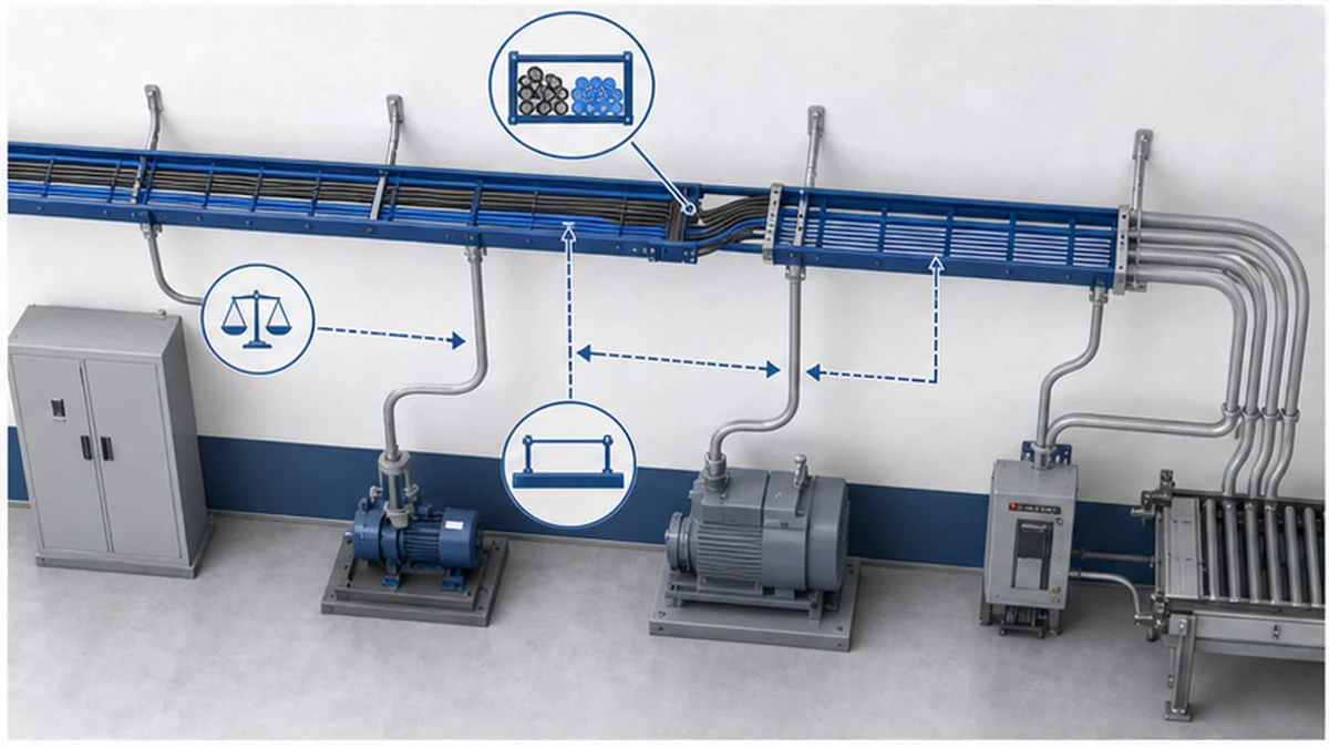
Detail of a protected equipment drop from overhead tray to conduit.
Frequently Asked Questions
Can cable tray and conduit be used in the same installation?
Yes. A common layout uses cable tray for the overhead main route and conduit for vertical drops or final connections where impact protection or an enclosed path is needed. The transition needs to be shown on drawings and checked for cable support, grounding, sealing, and access.
Is cable tray suitable for outdoor or wet areas?
It can be, provided the tray material, coating, cover, drainage arrangement, cable jacket, and support hardware suit the exposure. Galvanized steel, stainless steel, aluminum, and FRP each have different limits. The project specification and local electrical rules decide the final selection.
Does conduit always provide better protection than cable tray?
Conduit gives stronger enclosed protection at exposed or impact-prone locations. It is not automatically better for long shared corridors with many cables, where tray can offer better access, inspection, and future capacity. Protection should be matched to the actual risk along each part of the route.
How should a team decide between tray and conduit on a new route?
Start with cable count, route length, environment, impact risk, future changes, and code obligations. Use tray where a shared, accessible distribution path is justified. Use conduit where the route is short, exposed, or needs an enclosed method. Document transitions rather than leaving them to site judgment.
What should be checked before adding cables to an existing tray or conduit?
For tray, check spare width, cable weight, support capacity, segregation, thermal conditions, and the tray manufacturer’s load data. For conduit, check fill, pulling conditions, bends, cable type, and any code limitations. A visual site survey should confirm the as-built route before a new cable is ordered.
Kevin Zheng
Kevin Zheng is a manager linked to Shanghai Xinma Busway & Cable Tray Co., Ltd. He writes technical content on cable tray systems, installation practice, sizing logic, load classes, and related standards for industrial and infrastructure applications.