Address
304 North Cardinal St.
Dorchester Center, MA 02124
Work Hours
Monday to Friday: 7AM - 7PM
Weekend: 10AM - 5PM
Address
304 North Cardinal St.
Dorchester Center, MA 02124
Work Hours
Monday to Friday: 7AM - 7PM
Weekend: 10AM - 5PM
Get premium quality cable management systems directly from the manufacturer.
Fill out the form below to receive our catalog and pricing.
Cable tray installation planning begins before a single bracket is drilled. The routing path, support spacing, and site conditions locked in during early layout directly control whether a 2026 project meets schedule, passes inspection, and stays within budget. In a pharmaceutical manufacturing plant expansion in Suzhou (2023), poor initial cable tray routing decisions forced a reroute of approximately 340 meters of ladder tray during commissioning — adding 19 days to the project timeline and increasing installed cost by roughly 22%.
Getting these decisions right the first time is not just about efficiency. It is about structural integrity, code compliance, and the long-term performance of the cable management system under the real conditions of the site.
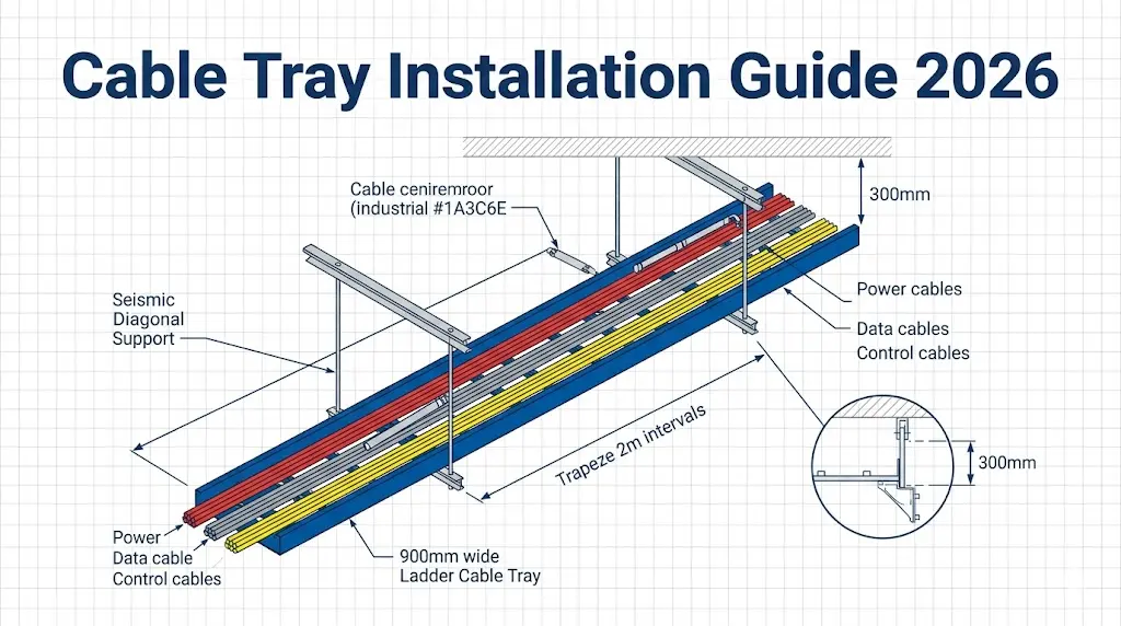
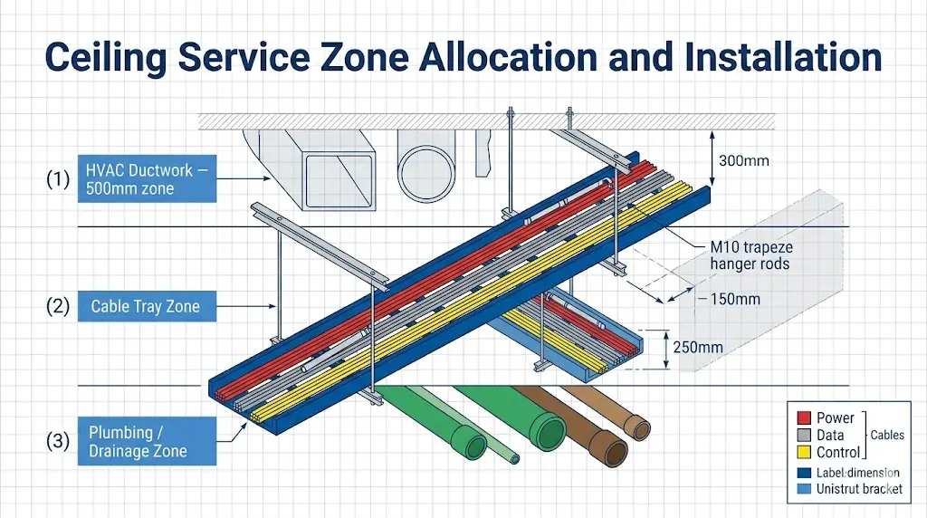
The cable management system must reserve adequate clearance from structural obstructions, HVAC ducting, and piping. IEC 61537 (cable management — cable tray systems and cable ladder systems) specifies that trays carrying power cables must maintain a minimum horizontal separation of 50 mm from other services unless a physical barrier is installed. Vertical separation between power and signal trays is typically set at 300 mm in industrial environments, though specific electromagnetic interference assessments may increase this.
Routing decisions also govern future capacity. A tray sized only for current cable fill leaves no room for additions or changes. Industry practice generally reserves 30–40% of the tray cross-sectional area for future cables, a figure consistent with NEMA VE 1 guidance on cable fill ratio management.
Support spacing is not a fixed number. It depends on tray width, material, load class, and span configuration. Ladder cable trays in 600 mm width at a 3-meter support span typically carry uniform distributed loads up to 150 kg/m within IEC 61537 Class C deflection limits. Reducing span to 1.5 m can nearly double the allowable load for the same tray section — a critical consideration in cable-dense plant areas.
Structural interfaces must be confirmed early: embedded inserts, beam clamps, or unistrut channels need to align with the tray support bracket positions determined during layout. Late discovery of interference between tray supports and structural steel is one of the most common causes of installation delay on large industrial sites.
Ambient temperature, corrosive atmosphere, and seismic zone classification each impose constraints that override standard catalog load tables. A coastal petrochemical site with salt-laden air requires hot-dip galvanized or stainless steel tray materials where standard pre-galvanized trays would degrade within 3–5 years. Seismic bracing requirements under GB 50981 or ASCE 7-22 add lateral support points that must be integrated into the original layout — not retrofitted later.
[Expert Insight]
- IEC 61537 deflection class C limits midspan sag to L/200 — for a 3 m span, that is 15 mm maximum; exceeding this accelerates joint separation and cable jacket stress at contact points.
- Field teams on cable-dense industrial projects consistently find that reserving 40% tray fill at design stage costs less than 8% more in tray material but eliminates the need for parallel supplemental trays during the first expansion cycle.
- Seismic lateral braces specified under ASCE 7-22 SDC C and above must be positioned before final hanger rod lengths are cut — retrofitting braces to an already-installed trapeze system typically requires full re-hanging of the affected bay.
- Routing path confirmation against final MEP coordination models (not preliminary drawings) is the single step most often skipped on fast-track projects, and the one most often responsible for costly field offsets.
Before the first bracket goes up, field conditions determine whether a cable tray installation meets specification or generates rework. On a 2024 petrochemical plant expansion in Shandong Province (approximately 18,000 meters of ladder tray across 12 process units), pre-installation field surveys identified three site conditions requiring design modifications before fabrication — saving an estimated six weeks of corrective work during the cable-pulling phase.
This is the practical starting point for any cable tray installation: understand what the site is actually doing before committing to hardware.
Cable tray supports transfer distributed loads directly into the building structure. Concrete inserts must achieve a minimum pull-out strength consistent with the imposed hanger loads — in standard ladder tray applications, each hanger anchor point should sustain at least 1.5× the calculated working load per applicable anchor-in-concrete pull-out standards (e.g., ETAG 001 or ACI 318 Appendix D equivalent). Expansion anchors in lightweight aggregate concrete typically achieve only 60–70% of the pull-out values measured in normal-weight concrete and may require closer support spacing or alternative fastening methods.
In a pharmaceutical plant fitout in Suzhou (2024, 18,000 m² facility), anchor pull-out testing at 24 random locations identified one entire bay of poured lightweight concrete that had been misidentified on structural drawings. Catching the issue before installation avoided a complete support redesign mid-project and an estimated ¥380,000 in retrofit costs.
Cast-in-place concrete accepts standard M10 anchor bolts with a minimum embedment depth of 70 mm, typically achieving pull-out values above 8 kN per anchor. Hollow-core precast slabs require toggle or spread anchors rated for the specific void geometry — standard through-bolt anchors are not reliable in that substrate. Steel beams accept beam clamps directly, eliminating drilling entirely, though the beam flange width must accommodate the clamp jaw (minimum 50 mm flange width is the practical threshold for most catalog clamps).
Steel cable trays expand at approximately 12 × 10⁻⁶ m/(m·°C). A continuous 30-meter tray run exposed to a 40°C seasonal temperature swing will grow roughly 14.4 mm. Without expansion splice plates at appropriate intervals, this movement transfers directly into support brackets and can crack welds or pull anchors.
Thermal expansion (ΔL) is calculated as: ΔL = α × L × ΔT, where α ≈ 12 × 10−6 m/(m·°C) for carbon steel, L is the tray run length in meters, and ΔT is the maximum temperature differential in °C. For a 30 m run with ΔT = 40°C: ΔL = 12 × 10−6 × 30 × 40 = 14.4 mm.
In outdoor or roof-level runs, design teams should verify the site’s recorded temperature differential — not just ambient design temperature — before fixing expansion joint spacing. In a 2024 petrochemical plant expansion in Shandong Province, failing to account for thermal movement on a 40 m outdoor steel ladder tray run caused three splice joints to buckle within six months of commissioning; rework cost exceeded the original installation labor.
For aluminum trays, the coefficient of thermal expansion is approximately 23 × 10⁻⁶ /°C — nearly double that of carbon steel. Expansion joints must be placed at intervals no greater than 15 m when routing through spaces subject to ΔT > 40°C between day and night cycles.
Expansion gap per joint (mm) = L × α × ΔT, where L is the tray run length in mm, α is the coefficient of thermal expansion, and ΔT is the expected temperature differential in °C. For a 15 m aluminum run with ΔT = 50 °C: 15,000 × 23 × 10−6 × 50 ≈ 17 mm — requiring a minimum 20 mm expansion joint gap with an allowance for installation tolerance.
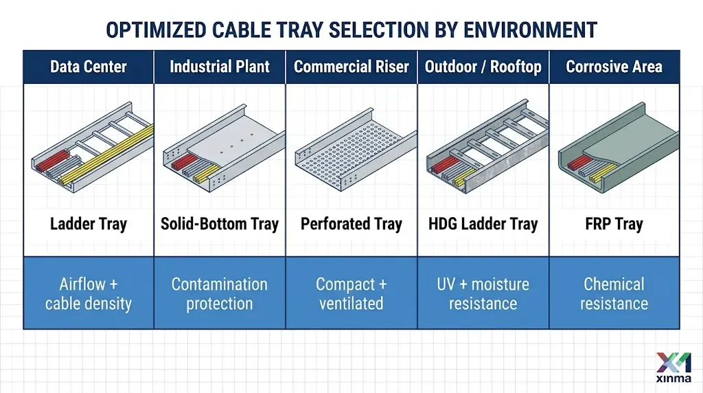
Field corrosion category — classified under ISO 9223 as C1 through CX — directly governs tray finish selection. A coastal or chemical process environment typically falls in category C4 or C5, where hot-dip galvanized coatings (minimum 85 µm per ISO 1461) are the baseline. Fiberglass reinforced polymer (FRP) trays become the preferred alternative for zones with direct acid or chloride exposure. Specifying plain pre-galvanized sheet (typically 20 µm coating) in a C4 environment will result in visible corrosion within 24–36 months under most field conditions
Temperature exposure adds another layer:
IEC 61537 recommends a minimum vertical clearance of 300 mm above the top of installed cable tray for cable pulling and maintenance access. Horizontal side clearances of at least 75 mm are typically required between adjacent trays or between a tray and a wall-mounted obstacle. In congested mechanical rooms, this is frequently the first dimension sacrificed during coordination — field surveys should measure actual headroom before tray elevation is finalized, not rely on BIM models that may not reflect late structural changes.
Horizontal corridor width for walking access alongside tray banks should be confirmed against local electrical code minimums — typically 600–900 mm depending on jurisdiction — before fixing support centerlines. In utility tunnels with ceiling heights below 2.4 m, stacking constraints often force a reduction in tray width from the designed 600 mm to 400 mm to preserve the mandatory clear maintenance walkway.
Walk every segment of the proposed route and document ceiling penetrations, existing MEP services, structural beams, and fire-rated barriers. Each duct crossing adds a fitting — typically an offset or junction section. Crossings with fire-rated compartments require fire-barrier sealing coordinated with the passive fire protection contractor before tray installation locks in the penetration location. Fire-stopping adds 2–4 hours of specialized labor per penetration and must be accounted for in the installation schedule.
Where trays pass through floor penetrations or are routed below raised floors, verify slab opening dimensions against tray width plus required fire-stop sleeve clearance. Openings are typically sized at tray width plus 50 mm on each side to accommodate intumescent material and sleeve flanges without compressing the tray sidewall.
[Expert Insight]
- ISO 9223 corrosion category mapping should be completed at the site survey stage, not after tray material has been ordered — switching from pre-galvanized to hot-dip galvanized mid-procurement typically adds 3–5 weeks to material lead time on larger projects.
- Anchor pull-out testing should be performed on a statistical sample of at least 5% of planned anchor locations on projects with mixed or uncertain substrate conditions; visual inspection alone is not sufficient to catch lightweight infill concrete misidentified on structural drawings.
- Thermal expansion joints in aluminum tray systems installed outdoors should include a closed-cell foam backing rod behind the gap seal to prevent debris ingress that could lock the joint and transmit thermal stress directly to adjacent support brackets.
- In seismic zones classified as GB 50981-2014 Zone II and above, lateral bracing hardware lead times frequently exceed 8 weeks; confirm availability before freezing the support layout.
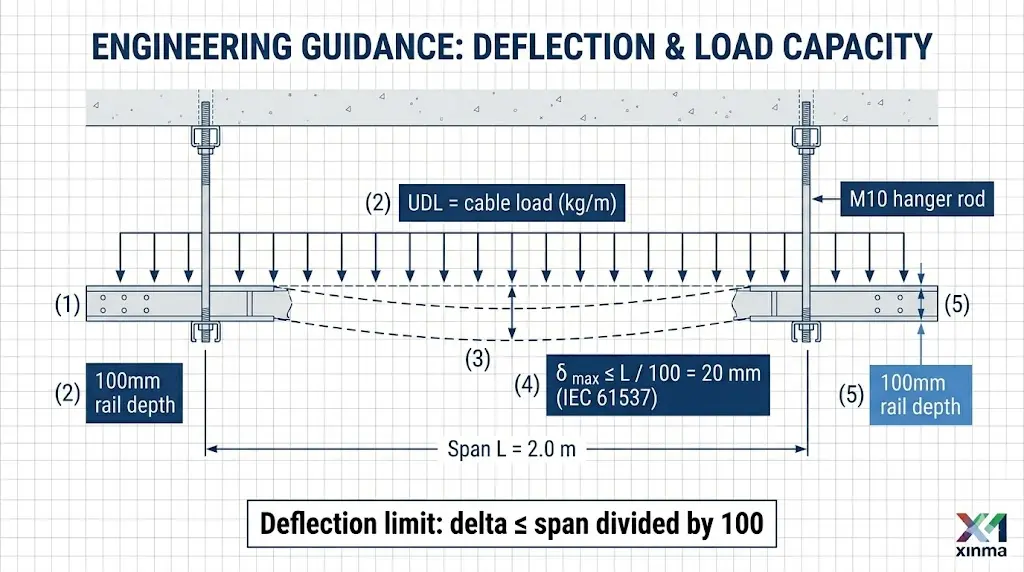
Proper support spacing is one of the most consequential decisions in cable tray installation — it directly controls midspan deflection, long-term structural integrity, and code compliance. Under IEC 61537, ladder-type cable trays spanning 3 m at full load class C (150 kg/m) must not exceed a deflection ratio of L/200, which limits midspan sag to 15 mm for a 3 m span. Exceeding this threshold risks cable damage and joint separation over time.
Support spacing is not uniform across all cable routing systems. Ladder cable trays — the most common type in industrial and data center environments — typically allow spans of 1.5 m to 3 m depending on rail depth and load class. Solid-bottom trays carry more dead weight per meter and generally require supports at 1.5 m intervals or less when fully loaded with power cables exceeding 50 kg/m.
In a 2024 pharmaceutical plant project in Suzhou (approximately 18,000 m² of cable routing), the engineering team standardized ladder tray spans at 2 m with hot-dip galvanized unistrut trapeze supports. This reduced material cost by 12% versus the originally specified 1.5 m spacing while keeping maximum deflection below 10 mm under verified load conditions.
For data center secondary distribution runs using 600 mm wide ladder tray at 75 kg/m cable load, each support spaced at 1.5 m carries approximately 112 kg. Before anchor selection, confirm the host structure’s allowable load from structural drawings — in older reinforced concrete facilities, embedded anchor pull-out capacity may limit support spacing below the standard 1.5 m, requiring an engineer’s approval.
Every support anchor must transfer tray load into the structural member — beam, concrete slab, or column — without slippage or fatigue failure under vibration. Threaded rod hangers are typically sized M10 or M12 for trays up to 600 mm wide, with a minimum embedment depth of 80 mm in concrete anchors per the fastener manufacturer’s pull-out rating. Field installers should torque anchor bolts to the rated specification — commonly 25–40 N·m for M10 stainless anchors — and never substitute hand-tightening.
In a 2024 pharmaceutical manufacturing plant in Tianjin (three-story, 18,000 m² floor area), preliminary load surveys revealed that existing concrete inserts were rated for only 120 kg each — well below the 200 kg hanger loads originally specified for heavy-duty ladder trays at 3 m spans. Reducing span to 1.5 m redistributed load to 95 kg per hanger and avoided a full structural reinforcement programme.
Thermal expansion requires at least one fixed (rigid) support point per straight run, with all other supports acting as sliding guides. For aluminum trays in outdoor environments, linear thermal expansion reaches approximately 2.3 mm per meter per 10°C temperature rise. Without expansion joints at intervals of 15 m to 30 m, buckled rails and anchor pull-out are predictable failure modes.
At vertical-to-horizontal transitions, two supports are required within 500 mm on each side of the change-of-direction fitting — consistent with NEMA VE 2 installation guidelines [VERIFY STANDARD: confirm NEMA VE 2 governs field installation practices]. This prevents cantilever-induced deflection at the most mechanically stressed point in the run.
Cable tray installation rarely matches the clean lines of a design drawing once crews reach the site. Structural obstructions, late-arriving equipment, and sequencing conflicts force layout decisions in the field — and those decisions carry structural and code consequences that ripple through the entire cable management system.
Before any tray section is hung, the installation crew should walk the full cable routing path and identify fixed constraints: beam flanges, ductwork, pipe runs, and sprinkler mains. In a 2024 automotive assembly plant retrofit in Guangzhou, the field team discovered HVAC ductwork 150 mm lower than shown on coordination drawings across a 40-meter run. Rather than re-engineering the support grid, the crew introduced a 200 mm vertical offset using factory-fabricated riser sections — maintaining the required 50 mm minimum clearance between the tray bottom and the duct surface. The adjustment added only two additional support points and kept the span under the IEC 61537 maximum of 3,000 mm for the specified load class.
In a 2024 pharmaceutical manufacturing plant expansion in Suzhou (40,000 m² facility), the cable tray routing team found that 23% of support anchor points fell within 150 mm of HVAC ductwork flanges, requiring field-fabricated offset brackets that shifted tray centerlines by up to 300 mm. These offsets were documented, re-engineered to maintain the 50 mm clearance minimum, and approved before installation continued. Without that clearance discipline, heat accumulation between the tray and ductwork would have required ampacity derating of cables inside.
Horizontal bends and tee fittings must be placed so that cable bend radius limits are never violated. For most power cables in the 35 mm² to 150 mm² range, the minimum bend radius is typically 12× the overall cable diameter. When space is too tight for a factory bend fitting, installers sometimes cut tray sections and splice at an angle — this is only acceptable if the splice point falls within 300 mm of a support bracket and the joint hardware is rated to the same load class as the tray body.
In utility tunnels and underground cable routing corridors, vertical stacking of multiple cable trays creates installation sequencing problems. The general rule is to install the lowest tray tier first, maintaining a minimum 300 mm vertical separation between power and control cable trays to manage electromagnetic interference and allow future cable pull access.
Field teams should document every deviation from the design layout — dimensions, photographs, and structural approval sign-off — before backfilling trenches or closing ceiling voids. Unrecorded field changes are the leading cause of cable tray load recalculation failures during facility expansion audits. Crews who sketch the as-built offset distances and support locations give the project engineer the data needed to verify that deflection limits and fill ratios remain within calculated values.
Support spacing depends on tray type, rail depth, load class, and the host structure’s anchor capacity — not a single fixed rule. Ladder trays under IEC 61537 Class C loading (150 kg/m) typically span 1.5 m to 3 m, with midspan deflection not exceeding L/200; confirm the specific span against the tray manufacturer’s load tables and the structural engineer’s allowable anchor loads before finalizing spacing.
IEC 61537 recommends a minimum of 300 mm of free vertical space above the top rail of an installed tray to allow cable installation, thermal breathing room, and maintenance access — in congested mechanical rooms, this dimension should be measured against actual site conditions rather than assumed from design drawings.
Sustained temperatures above 60°C can cause delamination of PVC coatings on steel trays, making hot-dip galvanized steel or FRP the appropriate choices; at temperatures below −20°C, carbon steel becomes brittle and notch-sensitive, favoring aluminum alloy tray systems with cold-rated polymer fittings.
Expansion joints are generally needed when a straight run exceeds approximately 15 m for aluminum trays or 30 m for steel trays in installations subject to seasonal temperature differentials greater than 30–40°C — the calculation ΔL = α × L × ΔT provides the expected movement that the joint must accommodate.
ISO 9223 corrosion category mapping provides the starting framework: C4 and C5 environments (coastal, chemical process) require hot-dip galvanized coatings of at least 85 µm per ISO 1461 at minimum, while zones with direct acid, chloride immersion, or hydrocarbon mist exposure generally favor FRP trays — with resin type (polyester vs. vinyl ester) selected based on the specific chemical agents present.
Each hanger anchor point should sustain at least 1.5× the calculated working load; for a 600 mm wide ladder tray at 75 kg/m cable load with 1.5 m support spacing, that equates to roughly 170 kg per anchor — cast-in-place concrete with M10 bolts at 70 mm embedment typically exceeds this, but lightweight aggregate or hollow-core substrates often require closer spacing or alternative fastener types verified by pull-out testing.
Every offset, bracket relocation, or span change should be recorded with dimensions, photographs, and structural approval before the area is enclosed or backfilled — this documentation allows the project engineer to verify that deflection limits, fill ratios, and clearance requirements remain within the values used at design stage, and prevents load recalculation failures during future facility expansions.
