Cable tray grounding and bonding must be designed as part of the project’s electrical safety system. A metallic tray section, splice plate, divider, cover, or support bracket should not be assumed to provide a required electrical path simply because the parts are in physical contact. The applicable code, project electrical design, tray material and finish, joint hardware, corrosion strategy, and test method together determine what must be installed and independently verified.
This article organizes engineering inputs, component interfaces, installation hold points, and evidence records needed for a documented route-level bonding control plan. It is not a substitute for the responsible electrical engineer or the requirements of the jurisdiction in which the work is carried out. Begin by identifying the selected cable tray system and its approved connection details before any installation or procurement decision is made.
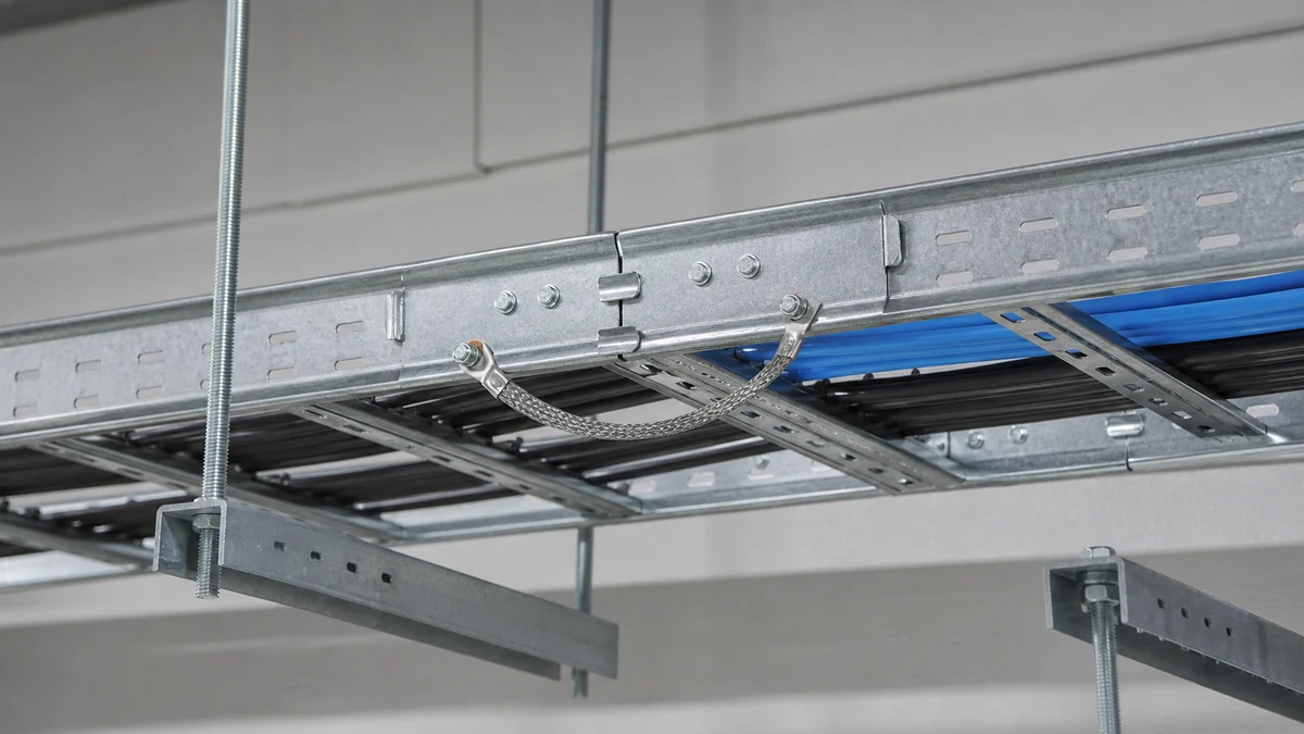
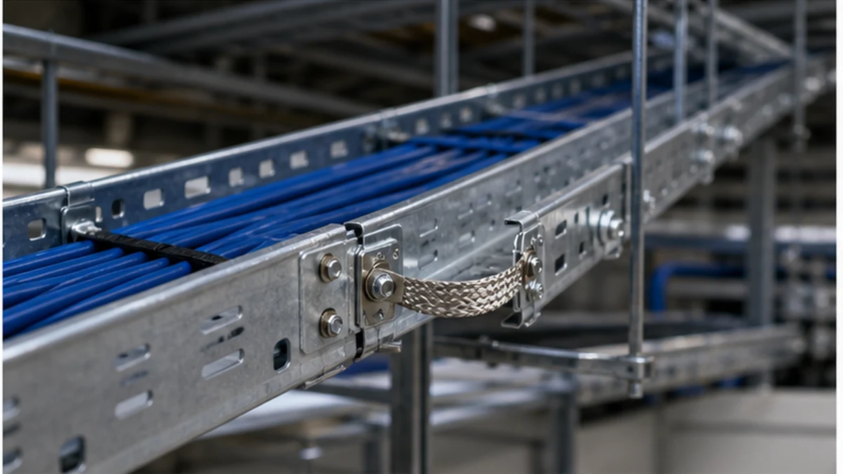
Cable tray bonding route
Design Inputs: Defining the Bonding Objective
The design record is the controlling document. Before a route is laid out or material is ordered, the responsible electrical engineer should confirm and record the following inputs.
Scope of bonding requirement. Identify which tray sections, fittings, and support structures require an electrical bonding or protective conductor arrangement. Not every metal component on a tray route necessarily forms part of that arrangement.
Conductor and conductor path decisions. The design must explicitly specify protective conductor sizing, routing, attachment method, and any jumper arrangements. These are electrical engineering decisions and must not be inferred from mechanical drawings or generic rules of thumb.
Joint and movement treatment. The design should state how expansion joints, building movement joints, and sliding mechanical connections are handled. A mechanical sliding interface does not automatically provide electrical continuity.
Material and finish dependencies. Coatings, paint systems, hot-dip galvanizing, stainless or aluminium alloys, dissimilar-metal interfaces, and post-fabrication coating repairs can all affect a connection. The design must account for the finish specified for the selected tray system.
Test and acceptance criteria. The method, instruments, responsible party, and pass criteria must be defined in the electrical design and applicable regulations. Do not transfer resistance thresholds or conductor sizes from another project without reviewing both designs independently.
IEC 61537 covers the cable tray product system. Refer to the IEC 61537 standard publication alongside the applicable electrical installation design and local regulatory requirements. The product standard and the installation design serve different purposes and are used together, not interchangeably.
Component and Material Interfaces
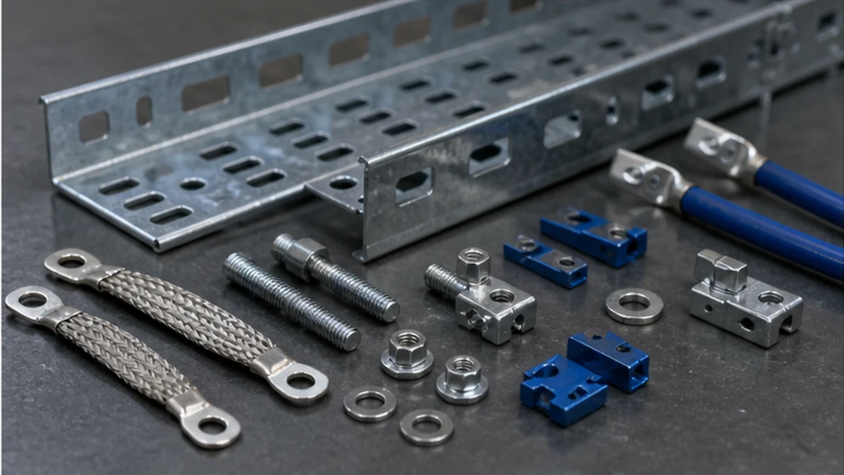
The procurement package for a bonding arrangement should identify bonding hardware, jumper assemblies where the design calls for them, lugs, fasteners, surface preparation requirements, protective treatments, and the exact tray system components to which each item attaches. Mixing generic hardware into a tray assembly when the approved detail calls for a system-specific finish, contact surface, or fastener torque is a common source of interface risk.
Review the selected cable tray fittings at every transition in the route: straight splices, elbows, tees, reducers, risers, equipment entries, and expansion locations. A route can appear continuously metallic on long straight sections while the required electrical path is interrupted at a fitting, cover plate, separator divider, or movement joint that has not been covered by the approved detail. A material checklist that traces each component back to a specific approved detail reduces the likelihood of a gap reaching installation.
Interface Type
Mechanical Function
Bonding Status
Action Required
Straight splice plate
Joins adjacent straight sections
Not confirmed by contact alone
Check approved detail and hardware
Elbow / tee fitting
Changes direction or branches route
Not confirmed by contact alone
Verify fitting-specific bonding detail
Expansion / movement joint
Accommodates thermal or structural movement
Sliding interface — continuity not assumed
Apply approved movement-joint bonding detail
Removable cover
Encloses cable space
Not a defined protective path unless stated
Treat as accessory unless design specifies otherwise
Separator / divider
Segregates cable groups
Not a defined protective path unless stated
Confirm with electrical design
Support bracket or hanger
Provides mechanical restraint
Not the defined bonding path unless stated
Verify from structural and electrical drawing
Fittings and Movement Joint Control
Expansion joints and building movement locations require a deliberate bonding detail in the approved drawings. A sliding mechanical connection may require a separate designed jumper or another approved method. The detail must specify the jumper type, length, attachment hardware, and whether the connection is installed before or after the joint is set to its installation position. Any ambiguity at this stage should be resolved with the responsible electrical engineer before installation proceeds.
Removable covers and separator dividers are frequently overlooked. Unless the project design explicitly identifies them as part of the bonding path and specifies how they are tested, they should be treated as tray accessories, not as protective conductors.
Cable tray bonding components
Support and Access Conditions
Support hardware has its own interfaces with the bonding design. Hangers, wall brackets, trapeze assemblies, and seismic-bracing components carry the tray mechanically but are not automatically the specified bonding route. Review the approved cable tray support planning resource and confirm that support positions do not conceal, damage, compress, or obstruct inspection of the defined connection points at any stage of the programme.
Access after installation is a practical control point. Where a support position, a riser transition, or a dropped-ceiling condition reduces access to a designed bonding point, the issue should be raised and resolved before the route is installed rather than after cables and finishes are in place. Document the decision and any approved revision to the support or bonding layout.
The accessories schedule should include mounting and inspection hardware appropriate to the installed support type. Cross-reference the cable tray accessories range to confirm system-compatible items, then rely on the approved electrical drawing for final connection selection. Do not substitute accessories based on dimensional similarity alone.
Installation Hold Points and Route-Level Workflow
A route-level bonding control plan should define hold points — stages at which installation pauses for inspection or verification before the work continues. The following workflow reflects a cautious approach and should be adapted to the project quality process.
Pre-installation hold point
– Confirm current drawing revision and approved bonding details for every joint type on the route.
– Verify tray material, finish, and component compatibility against the procurement record.
– Confirm that all specified bonding hardware and jumper assemblies are on site and correctly identified.
– Identify all movement joints, fitting transitions, and cover zones that require individual attention.
Mid-installation hold point (before covers and finishes are applied)
– Inspect all accessible bonding connections against the approved detail.
– Confirm surface preparation has been carried out where the detail requires it.
– Record photographic evidence for connections that will be concealed by covers, building finishes, or ceiling systems.
– Raise non-conformance records for any connection that does not match the approved detail.
Pre-handover hold point
– Complete the route-level inspection record with drawing revision, tray material, connection locations tested, test method and instruments used, results, exceptions, corrective actions taken, and responsible party sign-off.
– Confirm that all non-conformances have been closed or formally accepted.
– Retain the record for reinspection reference when future modifications are made.
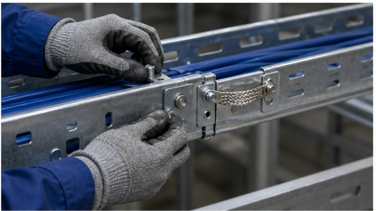
Cable tray bonding installation
Before installation begins on each section, verify the drawing revision, tray material and finish, joint type, bonding component specification, surface preparation instruction where applicable, and planned test points. Refer to the cable tray installation guide for wider sequencing context, and integrate the bonding hold points into the installation programme rather than treating them as a separate or optional activity.
Evidence Records and Post-Handover Reinspection
The test method, acceptance criteria, instruments, and responsible party must follow the project electrical plan and applicable regulations. Resistance thresholds and conductor specifications are electrical engineering decisions; do not copy values from another site or another project without an independent engineering review of both designs.
The inspection record should capture the tested route, drawing revision referenced, tray material and finish, location of each tested connection, any exceptions or deviations, corrective actions taken, and final sign-off. A well-structured route-level record serves an additional purpose: it makes future modifications traceable.
Reinspect any route section modified after handover work begins. A new cable entry, replacement fitting, added cover, or expansion-joint adjustment can alter the installed arrangement in ways that are not visible from the outside. Retaining the route-level record allows a future engineer or inspector to compare the as-modified condition against the original design without relying on assumptions about what was originally installed.
Cable tray bonding inspection
Xinma Ecosystem Coordination
Xinma manufactures cable tray sections alongside a coordinated range of fittings, accessories, busway components, and seismic-bracing assemblies. For route-level bonding control, the practical benefit is that model codes, finish specifications, splice and fitting geometry, support-interface dimensions, and approved connection hardware can all be traced through a single bill of materials. That traceability allows the site team to compare installed parts directly against the electrical detail, confirm that no generic substitutions have been introduced at a fitting transition or movement joint, and maintain an inspection record that is tied to specific components rather than inferred from visual appearance. Before final close-out, site teams should verify that seismic-bracing positions do not obstruct designed bonding points, that busway interfaces are covered by an explicit bonding detail in the electrical design, and that any field-applied accessories are confirmed as compatible with the finish and geometry of the installed tray system.
Frequently Asked Questions
Is a bolted cable tray splice always a sufficient bonding connection?
Not automatically. Physical contact and mechanical clamping do not confirm that the joint meets the electrical continuity requirements of the project. The approved electrical design must define the required hardware, surface condition, and connection method for each joint type on the route.
Do support brackets and hangers provide the required grounding path?
Not by default. Support hardware provides mechanical restraint and position control for the tray. Whether a bracket also forms part of the bonding arrangement is a decision that must be explicitly stated in the approved electrical design and must be verified independently.
How should an expansion or movement joint be treated for bonding purposes?
Use the approved movement-joint bonding detail. A sliding mechanical interface should not be assumed to provide electrical continuity under all operating and movement conditions. The detail must specify the jumper type, attachment hardware, and installation sequence relative to joint setting.
Can a removable cover or separator divider be used as a protective conductor?
Only if the responsible electrical design explicitly defines and verifies that use, including specifying the connection method and test requirement. In the absence of that explicit definition, covers and dividers should be treated as tray accessories, not as elements of the required bonding path.
What should the handover bonding record contain?
At a minimum: the drawing revisions referenced, route identification, tray material and finish, location of each tested connection, test method and instruments used, acceptance criteria, results, any exceptions or deviations, corrective actions taken, and the sign-off required by the project quality process. The record should be structured so that a future engineer can use it as a baseline when modifications are made to the route.
Kevin Zheng
Kevin Zheng is a manager linked to Shanghai Xinma Busway & Cable Tray Co., Ltd. He writes technical content on cable tray systems, installation practice, sizing logic, load classes, and related standards for industrial and infrastructure applications.