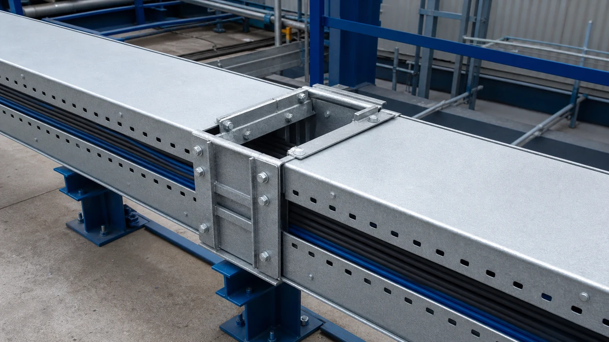
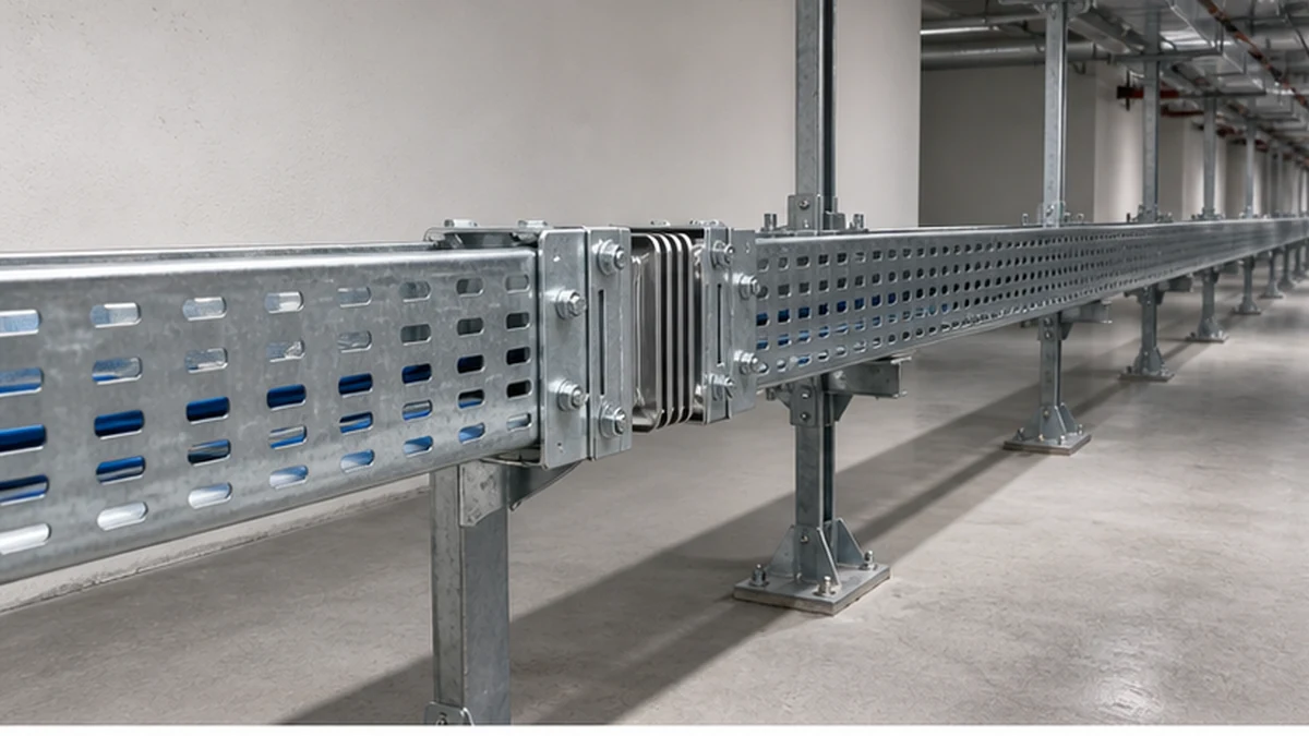
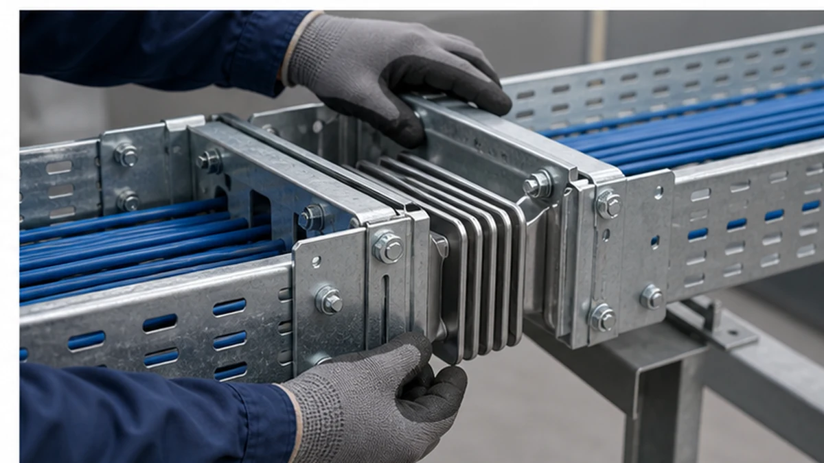
Cable tray expansion joints allow a tray assembly to accommodate movement that may arise from temperature change, long continuous runs, building movement, or a structural expansion location. They are not a generic accessory to be added at a fixed interval or calculated from a universal formula. The selected component, joint gap, bonding detail, support arrangement, cable allowance, and installation setting must each match the system drawing and the project’s movement assessment before work begins.
The sections below provide a structured approach to coordinating an expansion joint across the full life of a cable tray system route, from initial movement-condition assessment through close-out inspection.
Cable tray expansion route
Movement-Condition Assessment
The first task is to characterise what the tray must accommodate. Work from the route drawing and confirm the following inputs with the project’s structural and electrical teams before specifying any component.
Movement-Condition Decision Table
Condition to evaluate
Governing input
Action required
Tray material and finish
Specification and procurement schedule
Confirm expansion-joint family matches exactly
Longest continuous tray section
Route drawing with dimensions
Identify locations where movement must be managed
Anticipated temperature range
Site climate data and operating environment
Feed into designer’s movement assessment
Indoor or outdoor exposure
Route classification
Confirm finish, sealing, and cover requirements
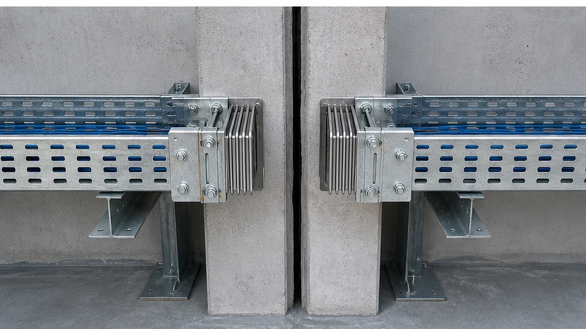
Structural building expansion joint
Structural drawings
Align tray joint location with structural joint
Transition between buildings or zones
Architectural and structural drawings
Confirm sleeve, fire-stopping, and access coordination
Passage through wall or into equipment
Penetration and equipment drawings
Confirm clearance, cover, and restraint detail
Do not translate a general thermal-expansion formula into a release-for-construction detail without verifying the selected tray system against this table. Each row represents a condition that may govern the joint location, setting, or hardware selection independently. IEC 61537 is relevant to the tray system as a product standard; use it alongside the project design documents rather than as a substitute for the movement assessment.
Component and Cover or Divider Compatibility Checklist
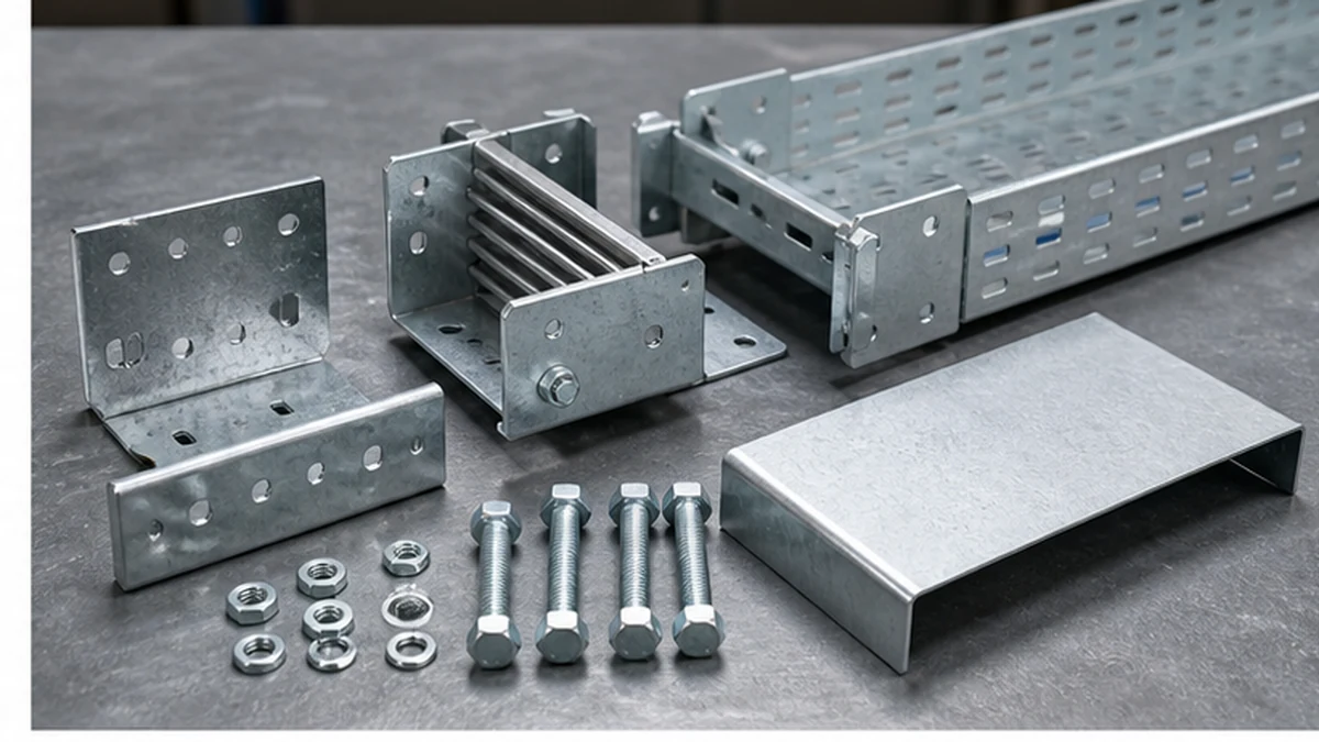
An expansion joint is typically more than a sliding mechanical connection. It may require matching side plates, splice hardware, fasteners, cover transition pieces, divider extensions, and bonding jumpers. Ordering parts from unrelated tray families introduces dimensional and finish mismatches that are difficult to correct after installation.
Use the checklist below before releasing a material order.
Component and Cover or Divider Compatibility Checklist
[ ] Expansion-joint assembly model code confirmed against tray family, material, width, depth, and finish
[ ] Side-plate hole pattern verified against tray sidewall profile
[ ] Fasteners specified in the manufacturer’s approved detail, not substituted from general stock
[ ] Cover transition pieces identified for the tray width and finish in use
[ ] Divider continuity method confirmed where cable separation is required across the joint
[ ] Bonding jumper type and routing identified where required by the electrical design
[ ] Permitted movement range for the ordered assembly confirmed against the project’s movement assessment
[ ] Special manufacturer instructions for continuity or bonding captured on the material takeoff
Cross-check required clips, cover pieces, and hardware against the cable tray accessories range for the specific tray family. Then obtain the approved component detail by reviewing the cable tray fittings range to confirm that the selected fitting matches the actual profile and finish. A joint that appears mechanically similar to an alternative may carry a different permitted movement range and should not be treated as interchangeable.
Cable tray expansion components
Cable Allowance and Bonding Coordination
Cable behaviour across a movement location requires deliberate design. The cable path must accommodate the intended joint action without being blocked by over-restraint and without creating unsupported loops or obstruction to access. The following items should be confirmed before cables are laid in and covers are fitted.
Cable Allowance and Bonding Coordination — Items to Confirm
Item
Design responsibility
Installer check
Cable slack across the joint
Electrical designer
Verify loop length matches approved detail
Minimum bend radius at allowance loop
Cable supplier data and electrical designer
Confirm no tight bend at restraint clamps
Restraint clamp positions on each side of joint
Electrical designer
Do not clamp within the movement zone unless detailed
Divider continuity across joint
Electrical designer
Confirm divider transition piece is fitted
Cover clearance over cable allowance loop
Electrical designer
Check clearance with cover in place
Cable separation maintained through joint
Route drawing
Confirm separation is not lost at the transition
Bonding jumper type and routing
Electrical designer
Install per approved detail, not assumed from mechanical contact
Bonding method recorded for inspector
Electrical designer
Visible notation on as-built drawing or inspection sheet
Do not clamp a cable so tightly on both sides of a movement location that the intended joint action is blocked. Equally, do not leave unmanaged cable loops that obstruct access or create an unsupported condition. Treat the bonding detail as a design item. The sliding mechanical connection should not be assumed to provide the required electrical continuity path unless the approved project detail explicitly states that it does. Record the approved bonding method and make it accessible to both the installer and the close-out inspector.
Support and Restraint Review
Support placement determines how an expansion joint functions. The joint detail should identify which tray sections are restrained and which are permitted to move, and that information must reach the crew installing the supports before any brackets are fixed.
Support and Restraint Workflow
Retrieve the manufacturer’s approved expansion-joint drawing and confirm it identifies restrained and free-moving tray sections.
Review the cable tray support planning guide alongside the joint drawing to align hanger type, bracket geometry, and spacing with the system detail.
Mark restrained support positions and free-slide positions on the route drawing before installation begins.
At structural movement locations, coordinate sleeve dimensions, fire-stopping systems, cover interfaces, and access requirements with the responsible structural and fire disciplines.
Confirm that no support crosses the movement zone in a way that would restrain both tray sections simultaneously.
Never cut a tray section or bridge an expansion joint in the field without an approved change detail signed by the designer.
A support placed across the wrong part of a joint can defeat the design even when the correct component was purchased and installed. This step should be treated as a site-hold point, not a routine check.
Cable tray expansion supports
Installation-Setting Verification
Before fitting any component, compare the delivered joint against the approved model code, material, finish, tray profile, and detail revision. A mismatch at this stage is easier to resolve than after cables are in place.
Pre-Installation Verification Checks
[ ] Delivered model code matches procurement schedule and approved drawing revision
[ ] Material and finish match the tray system (confirm coating type and class)
[ ] Tray profile and width match the assembly’s designed interface
[ ] Supplier’s installation instruction is available on site and revision is current
[ ] Joint gap is set in accordance with the supplier’s instruction for the project’s expected installation-temperature condition — do not apply a generic field gap
[ ] Hardware torque or clamping sequence follows the manufacturer’s instruction
[ ] Cover, divider, and cable route are inspected while the joint remains accessible
Add a dedicated inspection hold point before cables and covers conceal the connection. The cable tray installation guide provides broader sequencing context for tray routes; expansion joints require this additional verification step because errors are difficult to detect once the run is loaded and covered.
Close-Out Inspection Record
A structured close-out record makes the installation verifiable and supports future maintenance or modification decisions. The table below identifies the items that should be confirmed before the route is handed over.
Close-Out Inspection Record — Expansion Joint Location
Inspection item
Confirmed
Notes
Component model code and revision match approved drawing
Installation gap setting recorded
Support positions match restrained or free designation
Cable allowance loop fitted and clear of obstruction
Bend radius at loop acceptable
Cable restraint clamps positioned outside movement zone
Divider transition fitted where required
Cover transition fitted and clear of cable loop
Bonding jumper fitted per approved detail
Bonding method recorded on as-built drawing
Fire-stopping or sleeve confirmed at wall penetration
Inspector signature and date
Retain a completed copy for the project record. Where multiple expansion joints are installed on a long run, complete a separate row set or record sheet for each location rather than using a single sign-off for the entire route.
Cable tray expansion inspection
Xinma Ecosystem Coordination
For expansion-joint locations specifically, Xinma’s manufacturing range includes the tray sections, compatible fittings, cover and divider transitions, joint hardware, seismic-bracing components, and busway interfaces that may appear on the same route. The value of working within one product ecosystem at a movement location is that tray profile dimensions, coating class, hole patterns, and cover interfaces share a common approved drawing set. This makes delivery verification more straightforward and reduces the risk of a cover or divider transition arriving on site without a matching tray sidewall geometry. Site-inspection checks become more consistent when the BOM draws from a single family: the inspector can cross-reference model codes against one approved detail rather than reconciling parts from separate systems. Where seismic-bracing requirements apply to the same route, confirm that the bracing hardware is coordinated with the expansion-joint restrained-support positions so that the two systems do not work against each other.
Frequently Asked Questions
Should every long cable tray run use the same expansion-joint spacing?
No. Joint locations and settings must follow the selected system detail and the project’s movement, material, temperature, and structural conditions. There is no universal spacing figure that applies across different tray materials, finishes, building types, or route configurations.
Can a standard splice plate be used as an expansion joint?
Only if the manufacturer’s approved project detail explicitly identifies that splice plate for the movement condition in question. A fixed splice plate and a designed movement component serve different structural purposes and should not be substituted for each other without an approved change from the designer.
Does a tray expansion joint automatically provide electrical continuity?
Do not assume so. The sliding mechanical connection may not provide a reliable or code-compliant bonding path. Follow the project’s defined bonding and continuity method for the selected system and record the approved method so that installers and inspectors can verify it.
How should cables cross a tray expansion joint?
Use the approved route detail for cable slack allowance, restraint clamp positions, minimum bend radius, cable separation maintenance, and inspection-access requirements. The allowance must accommodate the intended joint movement without blocking it and without creating unsupported or obstructed cable conditions.
Why are support positions critical at a tray expansion joint?
Supports determine which tray section is restrained and which is free to move. A support placed incorrectly can prevent the joint from functioning as designed, even when the correct component has been purchased and installed. Confirm restrained and free-slide positions against the manufacturer’s approved drawing before fixing any bracket.
Kevin Zheng
Kevin Zheng is a manager linked to Shanghai Xinma Busway & Cable Tray Co., Ltd. He writes technical content on cable tray systems, installation practice, sizing logic, load classes, and related standards for industrial and infrastructure applications.