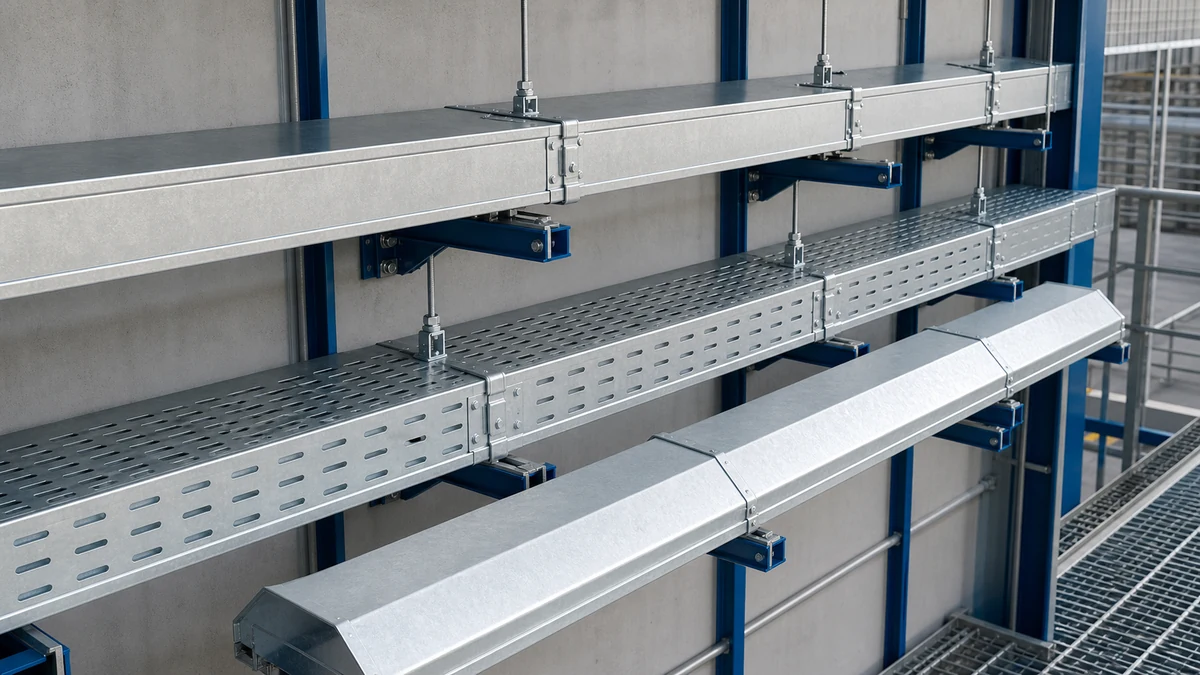
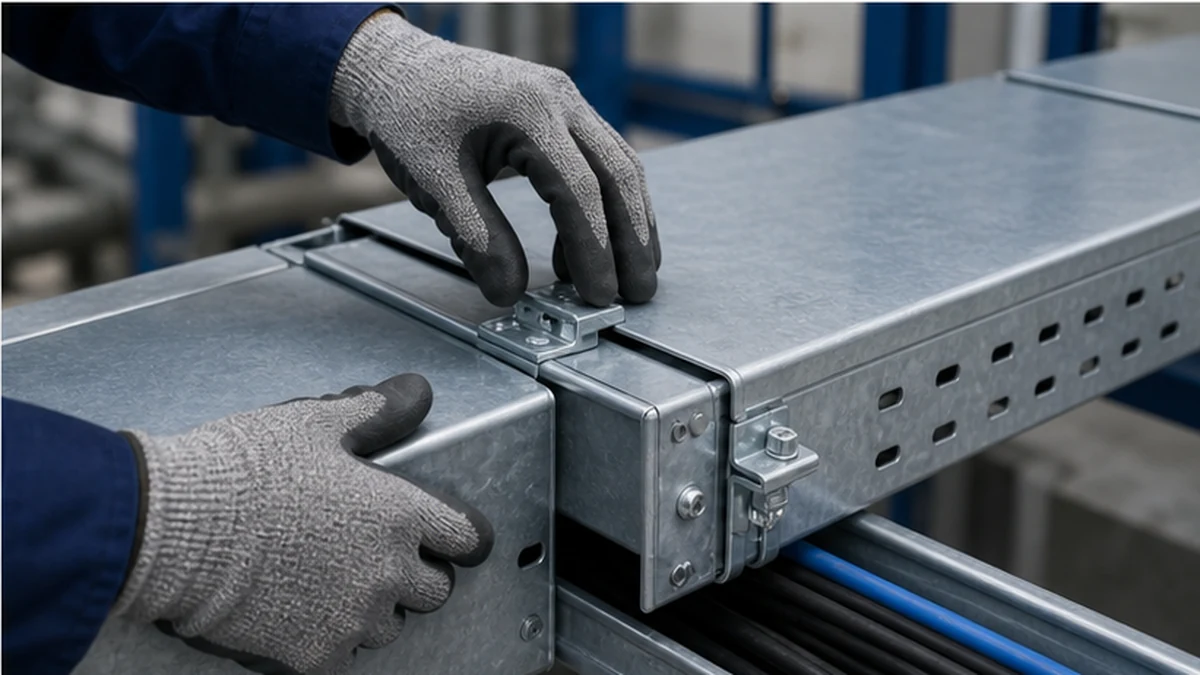
Cable tray covers protect a routed cable system only when their shape, jointing, fixing, material, and maintenance access match the actual route conditions. The practical choices are solid covers, ventilated covers, and peaked covers. Each form addresses a different exposure condition. None should be specified as a generic substitute for the project’s fire strategy, ingress-protection requirement, or cable-temperature calculation.
This article explains how to select a cover form from documented route conditions, how to verify continuity through fittings, and how to build a cover system that supports installation and long-term maintenance. For the broader product family, begin with the cable tray system range.
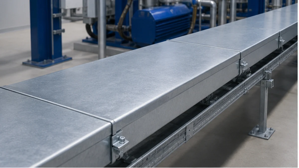
Solid cable tray cover
Conduct a Route-Exposure Review Before Selecting a Cover Type
Start with a route-by-route exposure review rather than applying one cover type to an entire project. For each segment, record the relevant conditions before making a selection.
Route-exposure checklist:
Indoor or outdoor location
Risk of falling dust, debris, or loose material overhead
Drip, condensation, or roof-leakage exposure
Washdown or chemical spray in the vicinity
Direct sunlight and UV exposure over the intended service life
Wind loading on covers and fasteners
Risk of unauthorized or incidental physical contact with cables
Required inspection and maintenance access frequency
Planned future cable additions or replacements
Identified heat sources near the tray route
Record each item against the tray segment reference on the routing drawing. The cover decision, the cable thermal calculation, and the fire strategy must all refer to the same route segment. A cover system that functions on one segment may be inappropriate on an adjacent segment with different exposure.
For cable tray mechanical-system context, IEC 61537 is a useful reference. Any fire performance, enclosure rating, corrosion resistance, thermal adequacy, or electrical installation requirement must be established separately by the project design; cover appearance alone does not demonstrate those attributes.
Cover Type Selection Table
The table below summarizes typical selection considerations. All entries are conditional on the documented project design; no cover type should be specified solely from this table without completing the route-exposure checklist above.
Condition
Solid Cover
Ventilated Cover
Peaked Cover
Falling dust or loose debris indoors
Preferred
Partial protection only
Not typical
Occasional drip or condensation indoors
Acceptable if drains confirmed
Less effective
Not typical
Ventilation of cable bundle is a design priority
Review thermal design first
Preferred
Depends on profile
Visual containment in occupied commercial space
Common choice
Acceptable
Less common
Outdoor route requiring runoff management
Limited
Not recommended
Preferred
Heavy outdoor debris or leaf accumulation
Not recommended alone
Not recommended
Review with end closures
High-frequency maintenance access required
Review removability
Easier access through openings
Review fitting access
Mixed indoor/outdoor route segments
Specify per segment
Specify per segment
Specify per segment
Where more than one cover type appears acceptable, confirm the cable manufacturer’s installation limits and coordinate with the electrical designer before finalizing the selection.
Solid Covers for Controlled Indoor Exposure
A solid cover is normally selected where the design needs to limit direct exposure to falling dust, loose material, or occasional drips, or where the route should be visually contained or less physically accessible. It can also provide a cleaner finish in exposed commercial installations. The protection offered by any solid cover depends on the quality of the full assembly: cover joints, end conditions, fitting covers, and clamp engagement all contribute.
Solid covers reduce air movement around the cable bundle. Before specifying them on a heavily loaded route, confirm that the electrical designer has reviewed the cable manufacturer’s installation limits and the project’s thermal assumptions. The route may experience heat sources, sprinkler discharge, or future cable additions that change whether a solid cover remains suitable over the service life.
Where a solid-bottom system is selected, confirm how the cover attaches to the matching solid cable tray section, splice plates, and fittings. A cover sourced from a different family may appear to match the width but leave unreliable sidewall engagement or interfere with a fitting transition.
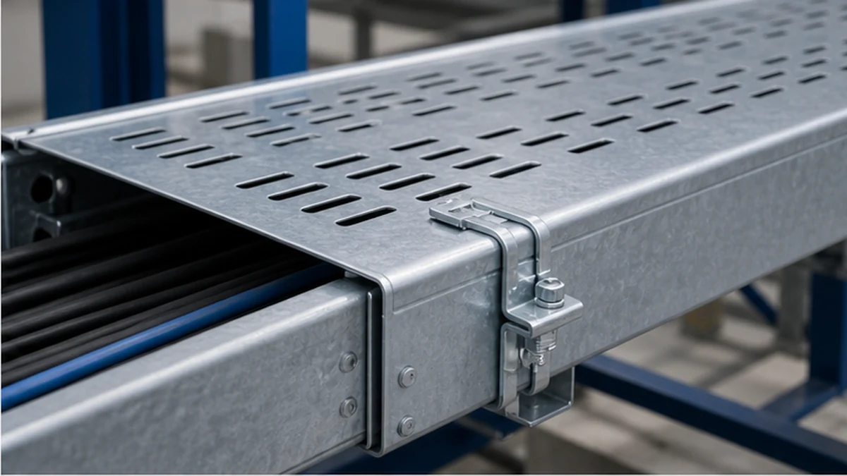
Ventilated Covers for Partial Shielding with Air Movement
Ventilated covers use slots, perforations, or similar openings to combine some overhead shielding with continued air movement around the cable bundle. They are commonly considered where dust control and visual containment matter but the design does not require a fully closed top. The open area, edge form, and clip arrangement vary between systems, so the procurement document should specify the system family, not only the generic term “ventilated cover.”
Use the approved cable calculation and environmental design brief to assess whether the available ventilation is appropriate for the route. Openings can admit dust, moisture, or small debris and do not make a route weatherproof. At changes in direction or elevation, a separate fitting detail may be required to avoid exposing cable bends.
For a perforated tray route, coordinate the cover and its fasteners with the tray’s perforation pattern and sidewall profile. The electrical cable tray guide provides wider context for selecting tray type by route and cable category; the cover decision should appear as a discrete item on the route schedule alongside the tray selection.
Ventilated cable tray cover
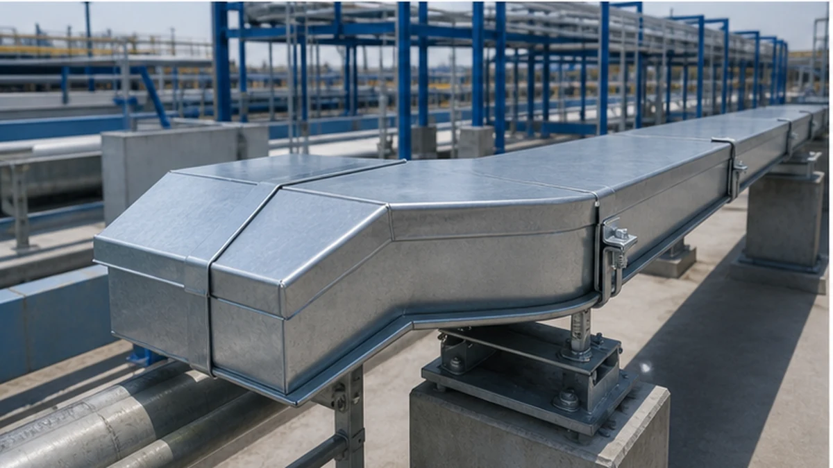
Peaked Covers for Outdoor Runoff Management
Peaked covers use a raised center profile to encourage water to run away from the top surface rather than pooling. They are commonly considered on outdoor routes where the project design calls for a drainage-oriented cover profile. Their practical usefulness depends on the complete assembly: direction of fall, overlap at joints, fitting covers, end closures, local wind exposure, and a maintenance plan for debris accumulation.
Do not describe a peaked cover as waterproof or weatherproof without a documented system requirement and tested assembly detail. Water can enter at cover joints, side gaps, transitions, damaged coatings, incomplete end closures, or changes in tray elevation. The cable selection and route design must account for the actual environment, not only the profile of the straight cover section.
When specifying material and finish, coordinate the peaked cover with the tray and support structure. Aluminum, coated steel, stainless steel, and FRP systems have different handling, corrosion, isolation, and fastening requirements. Request the supplier’s matching accessory and fitting list rather than mixing a generic peaked cover into an otherwise coordinated system.
Verify Compatibility at Fittings and Supports
Cover continuity is most commonly compromised at direction changes or elevation transitions. Before material release, review every bend, tee, cross, reducer, riser, drop-out, equipment entry, and expansion location on the routing drawing.
Fitting and clamp compatibility matrix — items to confirm at each transition:
Transition Type
Factory Fitting Cover Available?
Field Fabrication Permitted?
Approval Required?
Clamp Interference Risk
Horizontal elbow
Confirm with supplier
Per project method statement
Structural or project engineer
Check hanger clearance
Vertical inside/outside bend
Confirm with supplier
Per project method statement
As above
Check bracket geometry
Tee or cross
Confirm with supplier
Typically restricted
As above
Check splice-plate access
Reducer
Confirm with supplier
Per project method statement
As above
Check sidewall step
Expansion joint
Confirm with supplier
Generally not permitted
As above
Check movement allowance
Equipment entry or dropout
Custom detail usually needed
Per project method statement
As above
Check cleat and cable bend
Support geometry also requires review. A cover clamp must not obstruct hangers, brackets, splice plates, cable cleats, or required working clearance. A closed tray can also restrict access to fasteners after cables have been pulled. Review the route as a coordinated assembly rather than treating the cover as a cosmetic addition.
Peaked cable tray cover
Compile the Complete Cover System in the BOM
The cover entry in a bill of materials should specify more than width and straight-section length. A complete cover BOM entry includes:
Tray family and model code
Cover type (solid, ventilated, or peaked)
Material and finish
Section lengths and quantity
Clamps and couplers with part references
Fitting covers for each transition type on the route
End closures and any required transition pieces
Approved method for field cuts, including any coating or edge protection required
Use the cable tray accessories range to cross-check that selected clips, couplers, closure pieces, and fixing hardware belong to the same system family. Conduct a route-level takeoff that includes fittings and spare hardware under the project’s procurement rules. Estimating only straight-section length routinely leads to shortfalls at fittings and increased field cutting.
Installation Acceptance Checklist
Install tray and mechanical joints first, then verify cover fit at a representative straight section and at least one fitting before closing an entire route. Use the following checklist at the pre-handover inspection.
[ ] Covers confirm to specified model code, material, and finish
[ ] Clamps engage correctly on sidewall without interfering with splice plates or hangers
[ ] Cover joints are overlapped or coupled per the supplier’s installation requirement
[ ] Edges are protected and safe for installer contact during and after cable pulling
[ ] Covers do not pinch or bear on cable sheaths
[ ] Fitting covers are installed at every bend, tee, cross, reducer, and entry point on the route
[ ] End closures are fitted at all terminations and drop-out points
[ ] Removable access points are identified and documented for maintenance
[ ] Field cuts have been treated per the project method statement
[ ] Damaged or incomplete sections have been replaced or documented for remediation
[ ] Difficult-to-access transitions have been photographed before cladding or secondary structure obstructs them
[ ] Cover system has been reviewed against the route-exposure checklist and any deviations are recorded
The cable tray installation guide covers the broader installation sequence. Add the cover-specific checklist above as a discrete inspection hold point before handover.
Cable tray cover inspection
Xinma System Coordination for Covered Tray Routes
Xinma manufactures cable tray sections together with a matched range of fittings, cover accessories, busway interfaces, and seismic-bracing components. For covered routes, the critical coordination task is verifying that model codes, finish, support geometry, and access interfaces are consistent across the entire selected assembly, from straight covers and clamps through to fitting covers, end closures, and any busway transition details. Seismic-bracing bracket positions should also be reviewed against cover clamp locations to confirm that fixings do not conflict or require field modification. The site inspection check should compare delivered covers, fittings, and clamps against the approved route drawing, confirm that every transition type has a supplier-documented cover detail, and record any substitution or field adaptation before cable pulling begins. A coordinated bill of materials that references Xinma model codes for each component type supports both procurement accuracy and consistent inspection records across the project.
Frequently Asked Questions
Are solid cable tray covers suitable for every indoor route?
No. A solid cover reduces ventilation around the cable bundle and restricts inspection access. Before specifying one, confirm the route exposure, the cable manufacturer’s thermal installation limits, the project’s maintenance access requirement, and any future cable addition provisions. Indoor location alone is not a sufficient basis for selection.
Do ventilated covers make a cable tray route weatherproof?
No. Ventilated openings can admit dust, moisture, and small debris. A ventilated cover provides partial overhead shielding but does not create a weatherproof enclosure. Where the project requires outdoor protection, use a route-specific assembly detail that addresses joints, fittings, end closures, and the local environmental conditions.
Does a peaked cover guarantee that water stays out of the tray?
No. The complete assembly determines how the system handles water exposure. Gaps at cover joints, fitting transitions, incomplete end closures, damaged coatings, or elevation changes in the route can all allow water ingress regardless of the straight-cover profile. The project design must define the drainage and exposure requirement; the peaked cover is one component of the response.
Can covers from a different supplier be used if the width appears correct?
Do not assume compatibility based on width alone. Sidewall engagement geometry, clamp design, fitting-cover interfaces, material, finish, and corrosion compatibility all vary between systems. Confirm the supplier’s documented compatibility statement before mixing components, and note any deviation in the project record.
What should a complete cable tray cover bill of materials include?
Include the tray family and model code, cover type, material and finish, section lengths, clamps, couplers, fitting covers for each transition type on the route, end closures, transition pieces, and the approved method for any field cuts including required edge or coating protection. A line entry limited to straight-cover length and width is insufficient for coordinated procurement.
Kevin Zheng
Kevin Zheng is a manager linked to Shanghai Xinma Busway & Cable Tray Co., Ltd. He writes technical content on cable tray systems, installation practice, sizing logic, load classes, and related standards for industrial and infrastructure applications.