A cable tray system in 2026 is a structural cable management system that supports and routes power, control, and data cables along defined paths, typically over spans of 2–6 m. It supplements or replaces conduit, providing open, inspectable support while controlling cable fill, deflection, and thermal conditions under defined load classes.
Modern systems include ladder, perforated, solid-bottom, and wire mesh trays, with widths commonly from 100–900 mm and load ratings around 50–200 kg/m under IEC 61537 or NEMA VE 1. Designers compare tray stiffness against uniformly distributed cable load plus maintenance or seismic loads; for example, a 600 mm ladder tray carrying 120 kg/m of MV cables may need 2.5 m spans to keep midspan deflection under L/200.
Tray selection constrains cable size, fill ratio (often 40–60 % of cross-sectional area), and support spacing, and is treated as part of the mechanical support system. Trays must transfer loads to structure, maintain electrical bonding, and preserve cable ampacity through adequate ventilation.
[Expert Insight]
– IEC 61537:2016 defines testing for load, deflection, and electrical continuity of cable tray systems, giving designers comparable performance classes across manufacturers.
– Checking tray deflection limits early can avoid mid-project span reductions that otherwise require many added hangers and revised anchor calculations.
Main Types of Cable Trays and How They Behave Structurally
Cable tray type governs how the system carries load, limits deflection, and responds to vibration or thermal movement. For a given span and working load, ladder, perforated, solid-bottom, and wire tray behave differently in bending and torsion, which drives support spacing and allowable cable fill.
Ladder Cable Trays
Ladder trays use two longitudinal side rails with transverse rungs at 200–300 mm spacing, acting like a pair of beams braced by rungs and giving high bending stiffness about the strong axis. To IEC 61537, heavy-duty ladder trays can reach around 200 kg/m over 4 m spans with deflection typically below L/200.
They suit large power feeders or multiple LV circuits where ventilation and easy clamping are important, especially with 3–6 m spans and supports far apart. Wide ladders (≥600 mm) can twist if loaded asymmetrically or supported off‑centre, so trapeze or twin‑rod hangers are preferred, and rung spacing must meet minimum cable support intervals, often ≤300 mm for MV or heavy LV. Ladder trays are a typical choice for heavy-duty runs such as main power routes where ladder cable trays must provide both stiffness and ventilation.
Perforated and Solid-Bottom Trays
Perforated tray has a punched bottom; solid-bottom has no openings, and both behave structurally like plate girders with good torsional stiffness and resistance to small concentrated loads. They are widely used for small-diameter control, instrumentation, or communication cables needing continuous support or where dropped objects and dust must not fall through.
Their main trade-off is reduced natural ventilation, which can raise cable temperature by roughly 5–15 °C in dense power runs and force ampacity derating of 10–25 % compared with ladder tray. Self‑weight is higher, so broad trays (≥450 mm) at 3 m spans can approach deflection limits under about 100 kg/m, often leading to shorter spans or thicker side rails; in wet environments, drainage and corrosion protection are essential. These trays align with applications where perforated cable trays offer continuous support without fully sacrificing ventilation.
Wire Mesh (Basket) Trays
Wire tray is formed from welded steel wires and behaves like a lightweight open grillage with lower bending stiffness than ladder or perforated trays, typically rated around 50–75 kg/m at 1.5–2.5 m spans. It is used for dense LV and data cabling with frequent drops and direction changes, such as above IT rooms or office ceilings, where easy cutting and re‑bending on site matters.
The open lattice makes wire trays more sensitive to point loads, so personnel must not stand on them and specifications often call for explicit prohibitions and signage. Cable ties and support clips must be selected to avoid damaging small-diameter data cables on wire edges, making wire tray suitable where cable tray systems prioritize flexibility over high structural capacity.
Channel / Trough Trays
Channel trays are narrow U‑sections, often 100–200 mm wide, acting as single cold‑formed channel beams with limited section modulus, spans usually ≤2.0 m, and loads ≤50 kg/m. They are used for short runs to single items such as individual motors, local panels, or where wall space is constrained.
Because the profile is narrow, side loading and offset supports can induce torsion, so supports should be directly under the channel or brackets should restrain rotation. Transitions from channel to ladder or perforated tray need reinforcement to avoid weak joints and misalignment.
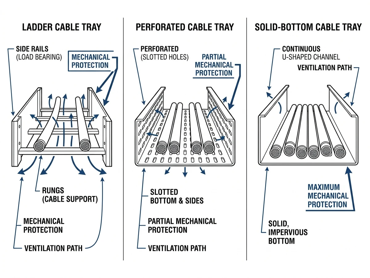
Figure 2. Cross-sectional comparison of ladder, perforated, and solid-bottom trays highlighting ventilation, cable support, and protection differences.
[Expert Insight]
– Channel trays are frequently overloaded with “temporary” cables; specifying a conservative 40–50 % fill limit helps prevent long‑term overload.
– Reinforced channel‑to‑ladder transitions significantly reduce vibration‑induced fatigue cracking at joints on rotating equipment skids.
Cable Tray Materials in 2026: Steel, Aluminum, and FRP Compared
Cable tray materials in 2026 are dominated by galvanized/painted steel, aluminum, and fiber‑reinforced plastic (FRP). Selection revolves around mechanical strength, corrosion resistance (C1–C5), weight, and electrical properties, which together determine support spacing, earthing approach, fault performance, and maintenance cycles.
Steel vs Aluminum vs FRP: Key Engineering Parameters
Parameter / Impact
Carbon/SS Steel Tray
Aluminum Tray
FRP (GRP) Tray
Typical density (affects dead load)
~7,800 kg/m³
~2,700 kg/m³
~1,800–2,000 kg/m³
Self‑weight, 300 mm ladder, 3 m length
12–18 kg
6–9 kg
7–11 kg
Load capacity at 3 m span (IEC 61537 Class)
Up to 200 kg/m (higher class)
Typically 100–150 kg/m
75–150 kg/m (profile‑dependent)
Corrosion performance
HDG: good in C3–C4; SS for C4–C5
Good in mildly industrial/marine; pitting in chlorides
Excellent vs chlorides/acids if resin is selected well
Electrical conductivity / bonding
Conductive – can act as bonding conductor
Conductive – can be used as equipment grounding path
Non‑conductive – separate PE conductor required
Fire behavior
Non‑combustible; strength reduces >500 °C
Non‑combustible; softens around 300–400 °C
Resin is combustible; needs tested fire rating
Thermal expansion (≈ mm per 10 m per 40 °C)
~4–5 mm
~9–10 mm
~8–12 mm
Common coating/finish
HDG, pre‑galv, epoxy, stainless
Mill finish, anodized
Polyester/vinyl ester resin with UV topcoat
Typical use cases
Heavy power, industrial plant, risers
Data centers, light‑medium loads, retrofit projects
Chemical plants, coastal yards, wastewater, offshore
Main advantages
High stiffness, strong fault path, cost‑effective
Low weight, easy to cut and handle, good conductivity
Corrosion‑resistant, non‑magnetic, non‑conductive
Main limitations
High weight, potential zinc/crevice corrosion
Lower stiffness, galvanic risk with steel supports
Higher cost, greater deflection, fire requirements
For detailed requirements on metallic cable tray systems, IEC 61537 is a primary reference: IEC 61537 publication page
Favor Steel, Aluminum, or FRP When…
Material choice should follow load–environment–earthing logic:
Use steel tray when spans exceed about 3 m or cable loads approach 150–200 kg/m, or where a robust metallic fault current path is required. It fits projects where structures can carry the extra dead load and corrosion classes are C1–C3, or HDG/painted steel can achieve acceptable life in C3–C4.
Use aluminum tray when dead load must be minimized but 75–150 kg/m ratings are needed at 2.0–2.5 m spans, such as roof routes, suspended slabs, or retrofits where manual handling and tight spaces dominate. It suits mildly industrial or marine environments with regular inspection to catch pitting.
Use FRP tray when corrosion class is C4–C5 or aggressive chemicals would reduce steel life to less than roughly 10 years without intensive maintenance, and when non‑conductive supports reduce touch‑voltage risk with a dedicated PE conductor. Spans are typically 2–3 m, accepting greater deflection for a given load compared with steel.
A common refinery example is a 400 mm tray carrying 100 kg/m in a coastal environment: FRP or stainless steel often provides better life‑cycle cost than HDG steel despite higher initial price, as repainting cycles for exposed HDG can be 5–7 years versus 15 + years before major intervention on correctly specified FRP systems.
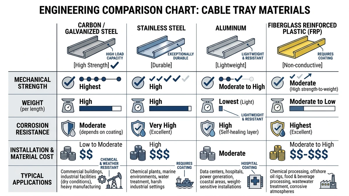
Figure 3. Material comparison chart summarizing carbon steel, stainless steel, aluminum, and FRP tray properties and typical environments.
Common Engineering Uses: Where Cable Trays Fit in Real Projects
Cable trays are used wherever large numbers of cables must be routed with defined spans, controlled fill, and predictable derating, typically in industrial plants, infrastructure corridors, and high‑density commercial or data facilities where conduit for every circuit would be uneconomical or hard to modify.
Process Plants and Heavy Industry
Refineries, chemical plants, and steel mills use ladder trays 300–600 mm wide on pipe racks and structural frames, spanning 3–6 m between supports. Mixed voltage levels (from 0.4 kV feeders to 24 V instrumentation) demand segregation, vertical spacing (often ≥300 mm), and barriers to manage EMC and fault risks, while frequent process changes favor re‑pulling or upsizing cables in existing trays.
Designers typically specify tray load class, span, and corrosion protection together, for example HDG or FRP ladder trays with ≥100 kg/m design loads on outdoor pipe racks in C4 environments to allow future circuits. In high‑seismic zones, added bracing at 6–12 m intervals on long runs can control sway and prevent cable damage.
Power Generation and Utility Corridors
In power plants and substations, trays carry LV and MV control and protection cables between control buildings, switchgear, and yard equipment. Long runs of 50–150 m make expansion joints and bonding jumpers necessary, particularly for aluminum and FRP, which may need expansion gaps every 15–30 m depending on temperature swing.
Fire performance and routing separation are critical near 6–35 kV equipment, so designers often follow IEC 61537 and local codes for fire barriers, fire‑rated supports, and avoidance of trays above escape routes. Tray types must integrate with trenches and duct banks, and where trays form part of the bonding path, splice plates and jumpers must be checked against fault current requirements.
Commercial Buildings and Data Centers
In offices, hospitals, and similar buildings, wire mesh trays often route 230/400 V power and structured cabling above ceilings, while data centers use wide (600–900 mm) ladder or wire trays to route hundreds of Cat 6A or fiber cables over cold aisles. IT trays are typically limited to 40–60 % fill to protect bend radii and signal performance, and supports are commonly at 1.5–2.0 m spacing to limit deflection at drop points.
Effective layouts rely on coordinating trays with HVAC ducts, sprinklers, and lighting to avoid rerouting that might breach bend‑radius or fill limits. For dense routes, using a method such as the cable tray size calculation approach helps pre‑size widths and speeds design iterations.
Applying These Design Basics with Xinma in Real Specifications
The design basics translate into core constraints on real projects: load class versus span, fill versus future capacity, environment versus material, and routing versus supports and fittings. Treating cable trays as structural, electrical, and maintenance assets at once leads to more robust specifications.
Load Class, Span, and Deflection
On a typical indoor 300 mm ladder tray, you might target ≤60 % fill and 3.0 m support spacing. If cable weight approaches 45–50 kg/m and a ~30 % future increase is expected, the main options are to increase tray load class (e.g., 75 → 100 kg/m at the same span) or to reduce spans to 2.0–2.5 m using more hangers but potentially lighter tray sections.
Comparing these options early saves redesign effort, considering material cost, installation labor, and compatibility with the structural grid. For further background on span and tray ratings, see the overview of cable tray dimensions and support logic.
Material, Environment, and Earthing
In corrosive outdoor routes, specifying hot‑dip galvanized or stainless tray is only one step; designers also check side‑rail thickness (e.g., 2.0–2.5 mm) for stiffness and corrosion allowance, wind uplift on covers for wide trays on roofs or pipe racks, and thermal expansion over 40–60 m straight runs, placing expansion plates or sliding supports at calculated intervals.
Where trays are part of the bonding system, splice plates, bonding jumpers, and earth connections must be verified for required short‑circuit and touch‑voltage performance under IEC and local standards. This coordination avoids later retrofit of additional bonding conductors or hardware.
Routing, Fittings, and Support Coordination
Cable tray selection dictates fittings (bends, tees, reducers), support types (cantilever, trapeze, stand‑off), and interfaces to other building systems. A practical workflow is to:
Define main routes and elevations, then assign tray type and material per section (e.g., outdoor HDG ladder, indoor aluminum perforated).
Fix maximum support spans from structural coordination, aligned with the building grid and anchor locations.
Use manufacturer load tables to check tray class against worst‑case cable weight plus a future allowance (often 20–30 %).
Doing this before detailed cable schedules are locked in can avoid late-stage issues where installed supports cannot meet deflection limits.
Installation and System Validation
Installation and inspection must confirm the assumptions used in design. Typical validation checks include measuring actual spans and comparing them with design values, confirming real cable weight and fill ratio at fully loaded sections (including reserved space), and inspecting bonding continuity across joints and to building earth.
Clear tray schedules that list tray type, class, span, environment, and material per route make installation and later modifications more predictable and reduce the risk of ad‑hoc overloading or non‑compliant repairs. For more on layout and field practice, see the stepwise cable tray installation guide.
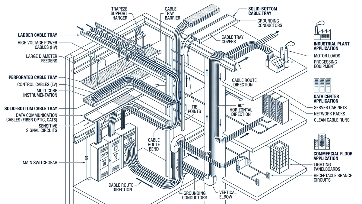
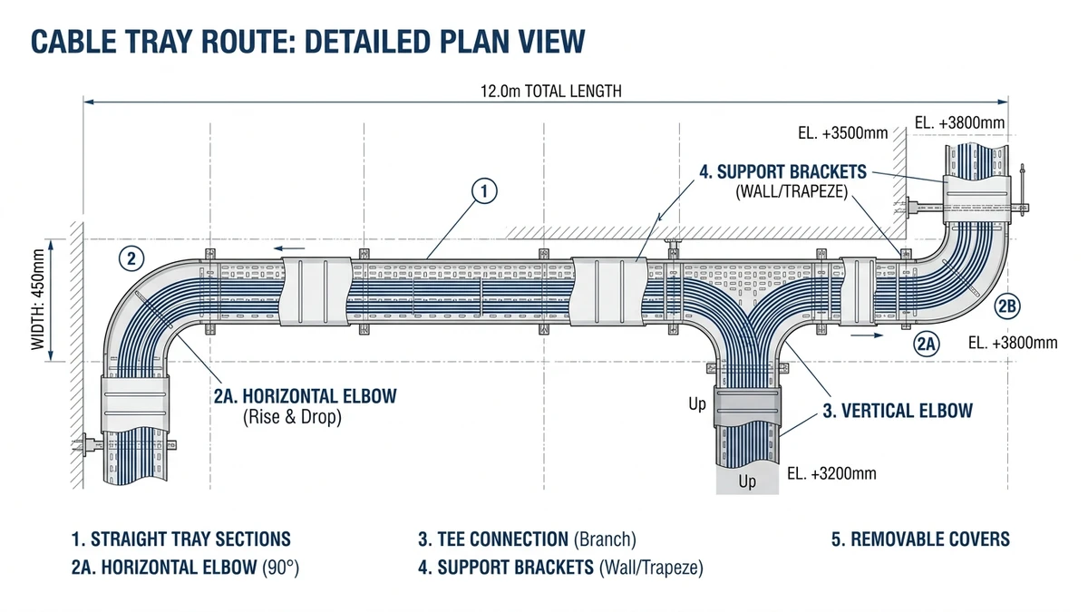
Figure 1. Basic cable tray route showing straight sections, fittings, supports, and optional covers with callouts for each function.
Frequently Asked Questions
How does a cable tray differ from conduit in electrical design?
Cable trays support multiple exposed cables along open routes, so designers must manage fill ratio, derating, and mechanical loading, while conduit encloses individual or small groups of cables with different short‑circuit and fire behavior considerations.
How do I decide the support spacing for a cable tray?
Select support spacing by checking manufacturer load–deflection data at your calculated cable weight per metre and choosing a span where deflection stays within the project limit (often L/200–L/250) with a margin for future cables.
When should I specify covers on a cable tray system?
Specify covers where cables are exposed to sunlight, falling objects, or contamination such as dust or dripping liquids, but confirm that cover use will not cause unacceptable thermal derating for heavily loaded power cables.
Can a cable tray be used as an equipment grounding conductor?
Metallic cable trays can sometimes be used as part of the equipment grounding path if they meet cross‑sectional area, continuity, and connection requirements, so designers should verify compliance with applicable electrical codes before relying on this function.
What is a reasonable future capacity allowance when sizing trays?
Many engineers reserve around 20–30 % additional fill capacity in key tray sections to accommodate foreseeable equipment changes without exceeding mechanical limits or forcing new parallel routes.
How do I choose between ladder and perforated tray for indoor runs?
Ladder tray is typically preferred for heavier power cables needing ventilation, while perforated tray suits lighter control or data cables needing continuous support, so compare cable type, fire strategy, and expected modifications before deciding.
Does cable tray material affect electromagnetic interference?
Non‑magnetic materials such as aluminum or FRP do not provide the same magnetic shielding as steel, so in areas with strong electromagnetic fields, steel tray or additional shielding may be considered depending on the sensitivity of nearby circuits.
Kevin Zheng
Kevin Zheng is a manager linked to Shanghai Xinma Busway & Cable Tray Co., Ltd. He writes technical content on cable tray systems, installation practice, sizing logic, load classes, and related standards for industrial and infrastructure applications.