For tray types, materials, finishes, and system selection basics, please see our
Cable Tray Systems pillar page.
For electrical code references related to support and installation practices, you can also review
NFPA 70 (NEC).
What is seismic bracing?
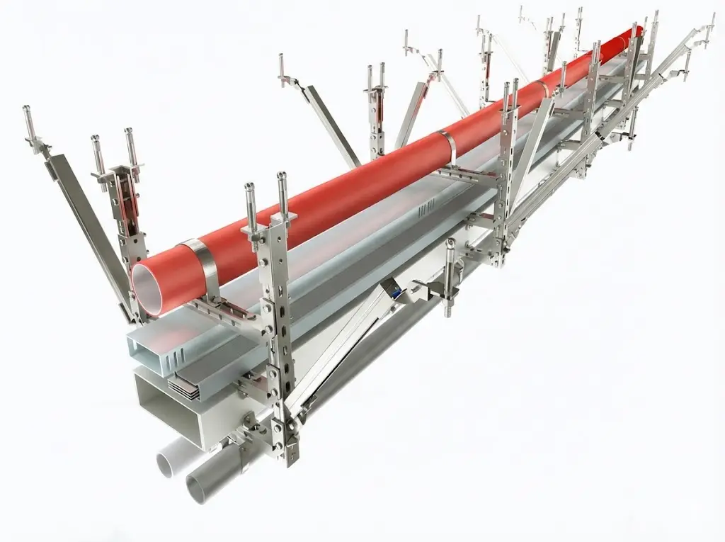
Seismic bracing is a restraint method that limits lateral sway and vertical movement of non-structural building services
(piping, ducts, cable trays, conduit, equipment) during earthquakes. A complete bracing system forms a controlled load path
using strut members, clamps, connectors, and anchors so the installation stays aligned and safe.
What does “seismic” mean in construction?
“Seismic” refers to effects caused by earthquake ground motion. In construction, seismic design focuses on keeping structures
and building services stable under shaking—preventing falling hazards, reducing damage, and maintaining functional routes for
life-safety systems and critical utilities.
How do I know if seismic bracing is required?
Requirements depend on the project’s seismic design category, occupancy importance, and the type/size of the MEP service.
Typically, the engineer of record specifies where bracing is required and how it must be installed. If you can share the application
(pipe/duct/tray), sizes, and the project location/code basis, the scope becomes much clearer.
What is the “12-inch rule” for seismic bracing?
“12-inch rule” is a commonly searched phrase, but the exact meaning varies by trade and local practice. In MEP work it is often used
as a shorthand for small-offset/short-drop conditions where additional restraint may or may not be required. Always confirm the actual
criterion from the project drawings/specs and the governing standard for that system (sprinkler, duct, pipe, tray, etc.).
What is the spacing for seismic braces?
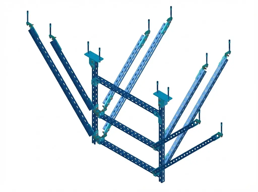
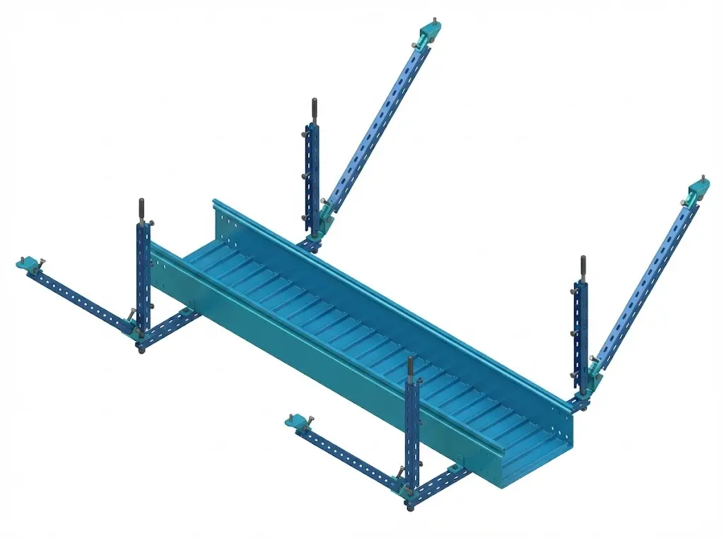
Brace spacing is not one universal number. It depends on the service type (e.g., pipe vs cable tray), load demand, attachment method,
and the project seismic category. Good practice is to follow engineered layouts: braces placed at defined intervals, at direction changes,
and near equipment interfaces so each run is restrained as a system.
What is ASCE 7-16 and why is it mentioned for bracing?
ASCE 7-16 is a widely referenced standard used in building codes to define design loads, including seismic loads.
MEP seismic restraint requirements are commonly derived from the project’s code basis and engineering calculations tied to ASCE 7.
In practice, it affects what must be braced, how forces are determined, and what attachment strength is required.
What is the NEC guidance for conduit support?
The NEC focuses on safe electrical installation, including support/securement practices for raceways and equipment.
For seismic conditions, projects typically combine NEC-conforming support with additional seismic restraint details specified by the engineer
or the local authority. The key point: standard support and “seismic bracing” are related but not always the same requirement.
Is seismic bracing required for Seismic Design Category D (or C)?
Category C and D projects more commonly require restraint for many non-structural services, but exact triggers vary by system type,
size/weight, and whether the service is life-safety or essential. The most reliable answer comes from the project’s seismic notes,
schedules, and the MEP bracing details on the drawings.
What is the “2% bracing rule” people talk about?
“2% bracing rule” is another popular search term that can refer to simplified field rules-of-thumb seen in certain trades or local practices.
Because it is not consistently defined across standards, it should not replace engineered requirements. Treat it as a conversation starter,
then verify the real criteria in the project documentation and governing code/standard.
How should seismic bracing be inspected and maintained?
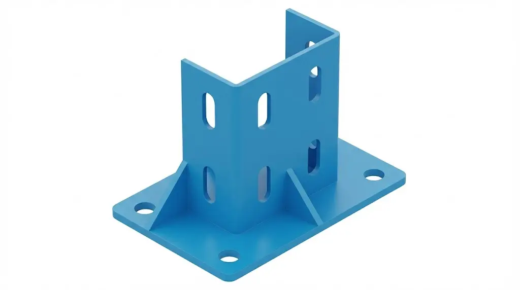
Inspection typically checks: correct brace locations, tightness and locking of fasteners, proper anchor installation, clear load paths,
and that clamps/connectors match the specified sizes. Maintenance focuses on corrosion, loosened hardware, and changes after renovations.
For life-safety systems, projects often follow the applicable inspection/testing standard listed in the building’s compliance documents.