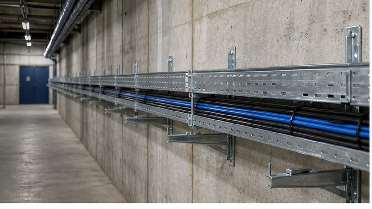
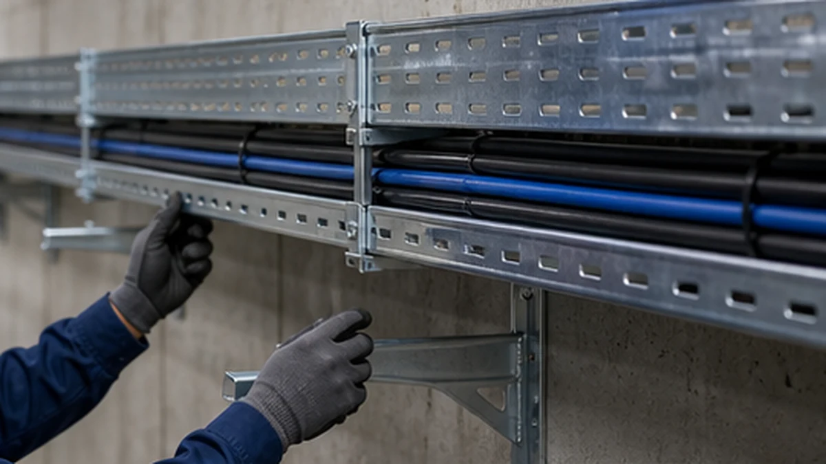
Cable tray wall brackets support routes that run alongside a wall, structural frame, service corridor, or equipment line. A bracket is not simply a piece of bent steel selected by tray width. The wall substrate, anchorage type, tray system geometry, installed cable load, fittings, covers, corrosion environment, required maintenance access, and the responsible project structural design all determine whether a side-mounted route is appropriate and how it must be supported.
The sections below provide a route-level decision matrix and coordinated checklist for wall-bracket selection, load accounting, accessory coordination, first-install inspection, and change control. None of the guidance here substitutes for the responsible project design. Begin by identifying the selected cable tray system and the approved route drawing before any bracket is specified or ordered.
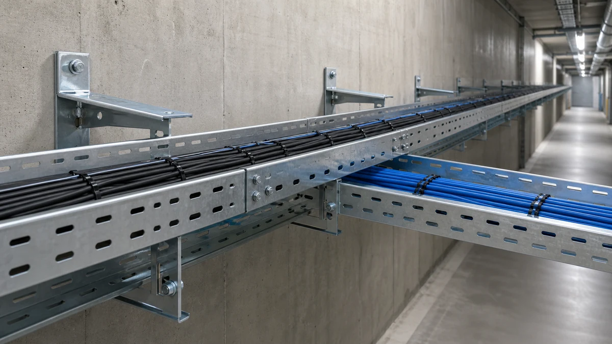
Cable tray wall bracket route
Wall Substrate and Anchorage Decision Matrix
The first decision in any side-mounted route is whether the supporting wall can accept the proposed anchorage at the required load and spacing. The table below identifies substrate categories and the coordination actions required before bracket selection proceeds. The responsible structural design must verify all items in the right-hand column; the table is a coordination prompt, not an approval.
Wall Substrate
Typical Constraint
Required Coordination Action
Cast-in-place concrete
Edge distance, embedment, reinforcement zone
Structural drawing review; approved anchor product and installation procedure
Masonry-specific anchor design; confirm grouted versus hollow condition
Structural steel framing
Flange width, connection type, vibration
Welded or bolted detail approved by structural engineer
Light-gauge metal framing
Low lateral capacity; typically nonstructural
Supplemental framing or load transfer to primary structure required
Composite or panel systems
Manufacturer load limits; thermal movement
Panel manufacturer data and structural sign-off before any penetration
Nonstructural partition
Generally unsuitable for tray loads
Redirect load to primary structure; do not anchor to nonstructural wall alone
Do not infer substrate suitability from the wall’s appearance, finish, or from a bracket product photograph. The structural design must address the actual load path, edge conditions, local reinforcement, and any project-specific approval requirements. IEC 61537 governs the tray product system; reference the IEC 61537 publication alongside the project structural and electrical documents when establishing system performance requirements.
Tray System Geometry and Bracket Compatibility
Match bracket geometry, material, finish, and attachment arrangement to the selected tray family before any material is released. The key compatibility checks are listed below.
Confirm whether the tray is supported below the rail, at the side rail, or through a dedicated accessory channel.
Verify that the proposed hardware does not interfere with splice plates, cable tie positions, covers, dividers, or required access to the cable bundle.
Check that bracket material and protective finish are compatible with the tray finish; mixing galvanized and stainless components in certain environments can introduce galvanic risk that the corrosion strategy must address.
Confirm bracket depth is sufficient to maintain the required cable bend radius at the wall face.
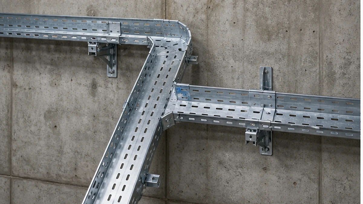
Use the approved cable tray fittings and route details to identify support requirements around elbows, tees, reducers, risers, and equipment transitions. Each fitting type can create a local load or geometry condition different from a straight tray section. The bracket is one component in a mechanical assembly; do not substitute it with hardware from an unrelated tray profile without a documented compatibility detail reviewed by the responsible design team.
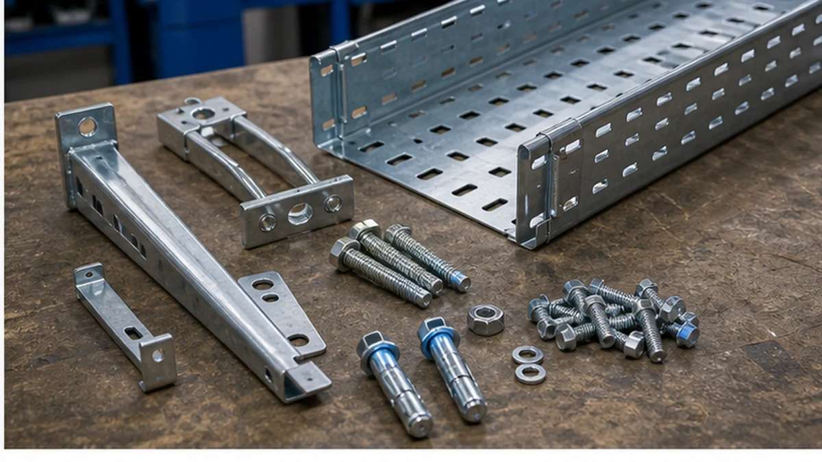
Cable tray wall bracket components
Installed Load and Environmental Conditions
The support design must account for the full installed condition, not the empty tray weight alone. Inputs that the responsible design team must evaluate include:
Exact tray model, nominal dimensions, and self-weight
All fittings, covers, and dividers on the route
Current cable fill weight based on the approved cable schedule
Approved future cable allowance, if any
Local load concentrations at fittings, equipment entries, or cover transitions
Any dynamic or vibratory load from adjacent equipment
A lightweight empty tray can represent a substantially different support case after cable pulling and cover installation. The responsible project design must determine support locations, anchorage sizing, load combinations, and any seismic or project-specific requirement. No universal bracket load rating, wall-anchor size, or maximum bracket spacing should be applied without the actual project design confirming those values for the specific substrate, tray model, and installed load case.
Environmental conditions affect material and finish selection independently of structural load. Outdoor exposure, periodic washdown, chemically corrosive atmospheres, and temperature-variable locations may each require a different coordinated detail. Confirm compatibility of bracket, tray, fasteners, protective treatment, and accessories against the project corrosion strategy before releasing material.
Fittings and Route-Level Support Workflow
Fittings require separate bracket checks because elbows, tees, reducers, and risers can introduce concentrated loads, change the load path, or restrict access to nearby anchors. The following workflow applies at the route-planning stage, before material release.
Mark all fittings on the route drawing and flag each for a dedicated support check.
Confirm that a bracket or supplemental support is located within the distance required by the tray manufacturer’s documentation for each fitting type.
Verify that the fitting support does not conflict with the fitting’s own hardware, cover attachment, or cable access.
Check that equipment entry points have a support on the tray side of the entry, not only on the remote side.
Review elevation changes for any unsupported cantilever condition that may not be visible on a plan-view drawing.
Document each fitting support location on the approved drawing before installation begins.
Treating a fitting as an extension of the adjacent straight run without a dedicated support check is a common coordination gap that is easier to resolve at the drawing stage than after installation.
Accessory Coordination and Bill of Materials
The bill of materials for a side-mounted route should include every item required to complete the mechanical assembly in its final installed condition. Cross-check the cable tray accessories range against the approved structural and tray drawings before releasing material. A representative BOM checklist for a wall-bracket route includes:
Wall brackets in the approved geometry and finish
Approved anchors and fasteners for the confirmed substrate
Tray-to-bracket attachment hardware compatible with the tray rail profile
Supplemental support components at each fitting location
Splice plates and bonding hardware at tray joints
Covers, dividers, and their attachment hardware where specified
Protective treatment materials for any field-cut or field-drilled surfaces, where the project corrosion strategy permits field work
Access hardware at inspection or pull points
Release only the material that appears on the approved drawings. If a field condition requires a substitution, use the project change process rather than selecting an alternative based on availability.
Cable tray wall bracket fitting
First-Install Inspection and Change Control
Before repeating the installation across a full route, inspect a representative bracketed section against the approved drawing. A hold point before cable pulling and before any finishing work makes anchors or tray joints inaccessible is strongly recommended. The inspection should confirm each of the following:
Structural and anchorage items
– Wall substrate matches the design assumption
– Anchor type, embedment, and edge distance match the approved detail
– Anchor installation procedure was followed and any torque or setting requirements are met
Tray and bracket items
– Bracket orientation and projection match the drawing
– Tray attachment hardware is complete and correctly tightened
– Route is level or graded as specified
– Fitting supports are in place at all flagged locations
Access and clearance items
– Clearance to adjacent services meets the approved route
– Cable and cover access is not obstructed by bracket position
– Splice locations are accessible and not behind a fixed bracket flange
Record all deviations while they can still be corrected without disturbing a completed cable run. If a field condition requires relocating a bracket, use the approved project change process after the structural and route implications have been reviewed. Drilling a new anchor location based on field convenience, without design review, is not an acceptable resolution. The cable tray support planning guide and the cable tray installation guide provide broader sequencing and coordination context for the full route.
Cable tray wall bracket inspection
Xinma System Coordination for Side-Mounted Routes
Xinma manufactures cable tray sections together with a coordinated range of fittings, accessories, seismic-bracing components, and busway products. For side-mounted routes specifically, the practical system check is that tray model, bracket geometry, fitting interfaces, protective finish, support hardware, and access requirements are all coordinated on a single bill of materials before any material is released to site. Seismic-bracing components, where required by the project structural design, must be confirmed compatible with the bracket attachment points and tray rail profile selected for the route; a seismic brace added after bracket selection can conflict with splice hardware or cover attachment. Accessory items such as cable dividers, earthing links, and cover clamps should be verified against the tray model at the same time as the bracket, because accessory-to-tray fit is model-specific. Site-inspection checks for Xinma-supplied systems should confirm that the tray identification markings match the approved model on the drawing, that finish condition is undamaged at all field-cut surfaces, and that any busway interface or equipment-transition detail uses only the compatible transition hardware specified for that tray family. The project structural and electrical teams retain responsibility for approving the actual wall anchorage design and the installed load case.
Frequently Asked Questions
Can a wall bracket be selected based only on cable tray width?
No. Tray width is one input among several. The bracket selection must also account for the tray system model, installed cable load, wall substrate, approved anchorage, fitting locations, corrosion environment, and access requirements. Selecting a bracket from width alone without confirming the other inputs can produce an incompatible or undersupported assembly.
Do all wall substrates accept the same cable tray anchors?
No. Anchor type, embedment depth, edge distance, and installation procedure depend on the actual substrate material and condition, the load path through the wall, and the responsible structural design. Concrete, masonry, steel framing, and composite panels each have different anchor requirements, and some substrates require supplemental framing before any tray load can be transferred to the wall.
Should fittings have separate bracket checks from straight tray sections?
Yes. Elbows, tees, reducers, risers, and equipment entries can create local load concentrations, geometry constraints, or access restrictions that differ from the conditions on a straight tray section. Each fitting location should be flagged on the route drawing and reviewed for a dedicated support detail before installation begins.
Can a bracket be relocated in the field to avoid a conflict?
Only through the approved project change process, after the structural and route implications of the new location have been reviewed by the responsible design team. A new anchor drilled at a convenient field location without design review may conflict with wall reinforcement, edge distances, or adjacent services, and the deviation will not appear in the as-built record.
What should be verified before cable pulling begins on a wall-bracket route?
Confirm that approved anchorage is in place and meets the installation requirements, that bracket orientation and tray attachment match the drawing, that fitting supports are installed at all flagged locations, that route clearance and access are unobstructed, and that any deviations from the approved drawing have been recorded and resolved through the project change process. Cable pulling over an unverified support condition makes subsequent correction significantly more disruptive.
Kevin Zheng
Kevin Zheng is a manager linked to Shanghai Xinma Busway & Cable Tray Co., Ltd. He writes technical content on cable tray systems, installation practice, sizing logic, load classes, and related standards for industrial and infrastructure applications.