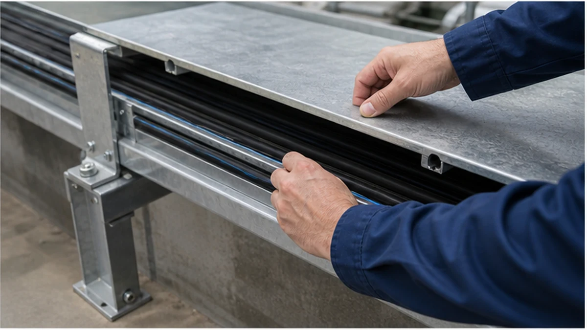
Cable tray influences the environment around installed cables, but it does not determine a cable’s current rating on its own. Heat accumulation, cable grouping density, route geometry, ambient conditions, solar exposure, cover selection, ventilation availability, and the cable manufacturer’s installation data all contribute to the thermal picture. A thermal derating review should therefore be a documented electrical-design exercise, not an assumption based on tray width or whether a cover happens to be fitted.
The sections below identify which route inputs must be gathered, how they should be coordinated, and what verification steps are needed before a covered or densely populated cable tray system is released for installation.
Thermal-Design Input Matrix
Before any calculation begins, every input affecting the thermal condition of the route must be captured in a structured record. The matrix below lists the categories that the design team should populate and maintain throughout the project. Missing or assumed entries should be flagged as open items, not filled with defaults.
This matrix is a live coordination document. When any cell changes, the electrical designer must be notified before further installation work proceeds on the affected route section.
Establish Cable and Route Inputs Before Sizing
Begin with the current, approved cable schedule. Record conductor construction, insulation type, outside diameter, quantity per route, circuit duty, routing length, grouping arrangement, and the manufacturer’s applicable installation method reference. Do not carry forward estimates from an earlier design stage.
Identify ambient conditions along the actual route, including enclosed plant rooms, roof spaces, equipment heat sources, outdoor sections, and any location where the route changes from open to covered. Each environmental zone must be logged separately; a single ambient value applied to a mixed route may understate the governing condition.
The calculation must use the project electrical-design method together with the cable manufacturer’s data. IEC 61537 governs the cable tray product system; the IEC 61537 publication should be consulted in its proper context, but it does not replace the cable-rating requirements that govern conductor selection. When a cable type or route condition changes during the project, revise the calculation, identify the revision source, and retain both versions in the design record.
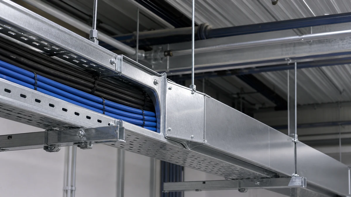
Cable tray thermal inputs
Treat Fill and Grouping as Thermal Inputs
Cable fill is not only a space question. A dense cable arrangement can alter the conditions assumed in cable-rating work and can make inspection, re-routing, and heat removal more difficult in service. Separate power, control, and data groups where the approved design requires it, and do not calculate a shared route as one undifferentiated cable bundle.
Use actual outside diameters and the approved lane arrangement to identify practical routing space. The cable tray size calculation guide helps frame the geometry check, but the electrical designer must confirm the thermal consequences for the selected cables and route conditions. No universal utilisation percentage should be applied as a thermal rule across different cable types or installation methods.
When a revised cable schedule increases the number of parallel power circuits in a route, the route must be returned to the electrical designer before installation begins on that section. Updating the cable-grouping plan before the pull phase is the controlled outcome. A field decision made after cables are installed and a cover is fitted is significantly more difficult to resolve without disruption to adjacent services.
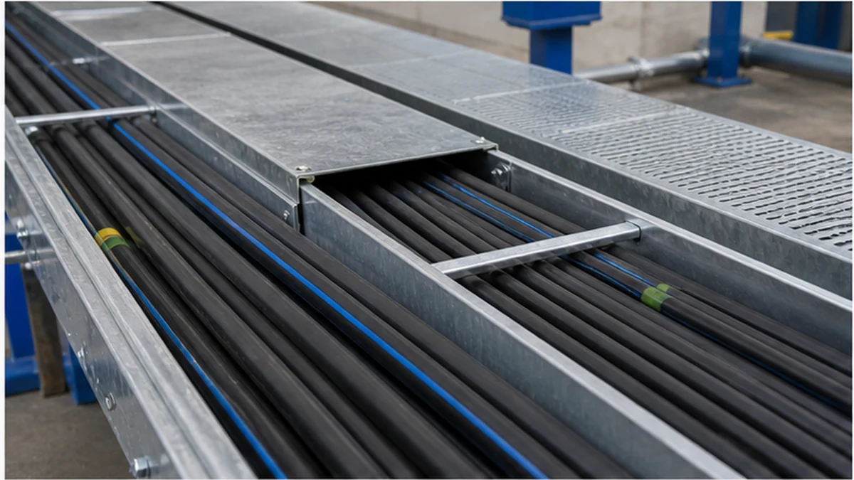
Cable tray thermal review
Check Covers as Part of the Whole Route
Solid and ventilated covers change a route’s exposure and airflow characteristics in different ways. A cover may be selected for debris protection, drip resistance, maintenance access control, or environmental classification, but it should not be described as thermally neutral or as automatically suitable for a given cable loading without an assessment.
Where a covered route is proposed, identify the matching cover system and confirm how it attaches to each straight section, bend, tee, and reducer fitting. A solid cable tray system provides the enclosure geometry needed for certain route environments, but the cable thermal assessment remains a project-specific design task regardless of which tray form is selected. For routes using open-bottom sections, verify the chosen perforated cable tray geometry and cover accessory detail rather than assuming all perforation patterns produce equivalent airflow conditions.
Cover joints, fitting covers, cable entry points, maintenance-access panels, and the route’s surrounding ambient environment all require review. An incomplete cover run—one that is open in sections for access or fitting clearance—should be documented so that the electrical calculation reflects the actual installation, not an idealised one.
Review Route Transitions and Support Clearance
The thermal condition can vary considerably across a single route. A long open section may enter a covered riser, pass near process equipment, cross an outdoor area exposed to solar gain, or terminate in a congested panel approach where cable bend radius reduces available space. Each transition point should be reviewed and the governing condition identified in the approved calculation.
Do not average environments across zones without a method accepted by the electrical design team. The transition between an air-conditioned electrical room and an unconditioned roof space, for example, may produce a step change in ambient condition that affects the selected cable size for the higher-temperature segment.
Support and hardware arrangements also affect cable access and group positioning. Hangers, cleats, dividers, splice plates, and cover clamps influence where cable groups sit relative to each other and whether the planned installation can be inspected or modified after commissioning. The cable tray support planning guide provides broader coordination context for that route review, including support spacing and hardware compatibility with the selected tray profile.
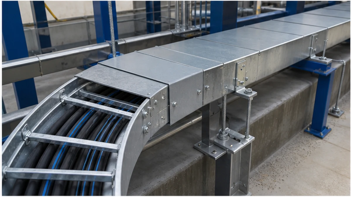
Cable tray thermal route transition
Controlled Handoff Workflow to the Electrical Designer
The following sequence describes the minimum handoff steps when a thermal-sensitive route section is ready for design sign-off. It is a coordination workflow, not a procurement or installation sequence.
Installer or project engineer compiles the input matrix for the route section, including all items listed in the matrix table above. Flag any open or assumed items explicitly.
Submit to electrical designer with the current cable schedule, tray geometry record, cover plan, and ambient-zone list attached. Do not omit route-transition details or partial-cover sections.
Electrical designer reviews and calculates using the cable manufacturer’s data and the project design method. Any cable, grouping, or cover change that falls outside the calculated conditions is returned as a design query, not resolved on site.
Electrical designer issues revised design record that confirms the accepted cable arrangement, cover extent, ambient zones, and any constraints on future additions. This record accompanies the installation package.
Site team acknowledges constraints before the pull phase begins. Any deviation from the issued record triggers a repeat of steps 1 through 4 for the affected section.
Retaining both the original and any revised records allows the commissioning team and future maintenance staff to understand what conditions the installed cables were designed for.
Pre-Pull Verification Checklist
Before cable pulling, compare installed tray conditions with the approved electrical design. The checklist below should be completed by the site supervisor and countersigned by the project engineer. Escalate any discrepancy before it is concealed by installed cables.
[ ] Tray type and profile match the approved design record
[ ] Cover type (solid or perforated) matches the specified cover plan for each section
[ ] Cover joints, fitting covers, and entry seals are in place and continuous
[ ] Cable lane arrangement and divider positions match the approved grouping plan
[ ] Support spacing and hanger type match the design and support schedule
[ ] Route-transition conditions (covered-to-open, indoor-to-outdoor) are recorded and match the ambient-zone log
[ ] Equipment heat sources near the route are confirmed as unchanged since the last design review
[ ] Cable outside diameters on the pull schedule match those used in the approved calculation
[ ] Any cables added since the last design revision have been reviewed and accepted by the electrical designer
[ ] The hold-point sign-off is completed and filed before pulling begins
A discrepancy in cable quantity, outside diameter, cover extent, or ambient condition found at this stage is a design-review trigger, not a site judgement call.
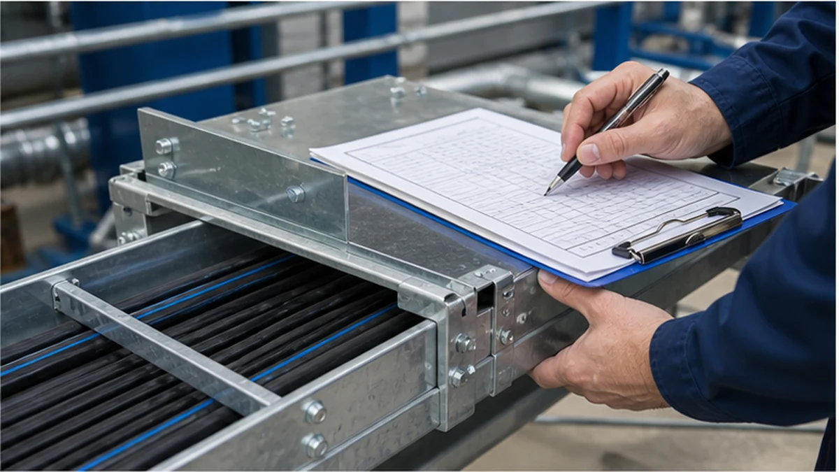
Cable tray thermal inspection
Xinma System Coordination
Xinma produces cable tray sections alongside a matched range of fittings, covers, dividers, splice accessories, busway components, and seismic-bracing systems. For thermal-route coordination specifically, the practical value of working within one product ecosystem is the ability to confirm compatible interfaces between tray profile, cover attachment, fitting cover geometry, support clamp design, and divider rail sizing within a single bill of materials. Mismatches between a tray section and a non-compatible cover or fitting can create unplanned open sections that alter the route’s cover continuity and, consequently, the conditions the electrical designer assumed. Seismic-bracing hardware should also be checked for clearance with cover clamps and cable cleat positions, particularly in transition zones where both bracing and covers are specified. Xinma’s site-inspection programme can confirm that installed components match the issued BOM before the pre-pull hold point is signed off, giving the electrical designer a verified basis for the design record rather than a paper assumption.
Frequently Asked Questions
Does an open cable tray eliminate the need for thermal derating review?
No. Cable current rating depends on the cable manufacturer’s data, circuit grouping, ambient conditions, installation method, and the approved electrical design. An open tray profile does not remove the obligation to assess those inputs. Route zones, support conditions, and cable grouping all remain relevant regardless of whether a cover is fitted.
Do covers always require a different cable calculation?
The effect must be assessed for the actual route, cable type, cover geometry, and ambient conditions. A cover should not be assumed to have no thermal effect, nor should the same effect be assumed across every installation. The cover type, continuity, and the cable arrangement beneath it are all inputs to the assessment.
Can fill ratio be used as a cable current-rating rule?
No. Fill ratio is a space-planning input, not a current-rating method. The electrical designer must use the applicable cable manufacturer’s data, installation method reference, and design calculation for current-rating decisions. A percentage fill figure does not substitute for that process.
What changes should trigger a formal thermal review?
Changes to cable quantity, cable type, insulation category, conductor size, grouping arrangement, route exposure, cover extent, tray profile, ambient heat sources, or support layout should be referred back to the electrical designer before installation continues. The thermal-design input matrix described above is a practical tool for identifying which cells have changed and whether they affect the governing design condition.
Why is a hold point before cable pulling necessary?
It confirms that the installed tray sections, covers, supports, dividers, and cable lanes match the conditions recorded in the approved electrical design. Discrepancies found after cables are pulled and covers are fitted are significantly more disruptive to resolve. The hold point is the last practical opportunity to compare physical conditions with the design record before the route is closed.
Kevin Zheng
Kevin Zheng is a manager linked to Shanghai Xinma Busway & Cable Tray Co., Ltd. He writes technical content on cable tray systems, installation practice, sizing logic, load classes, and related standards for industrial and infrastructure applications.