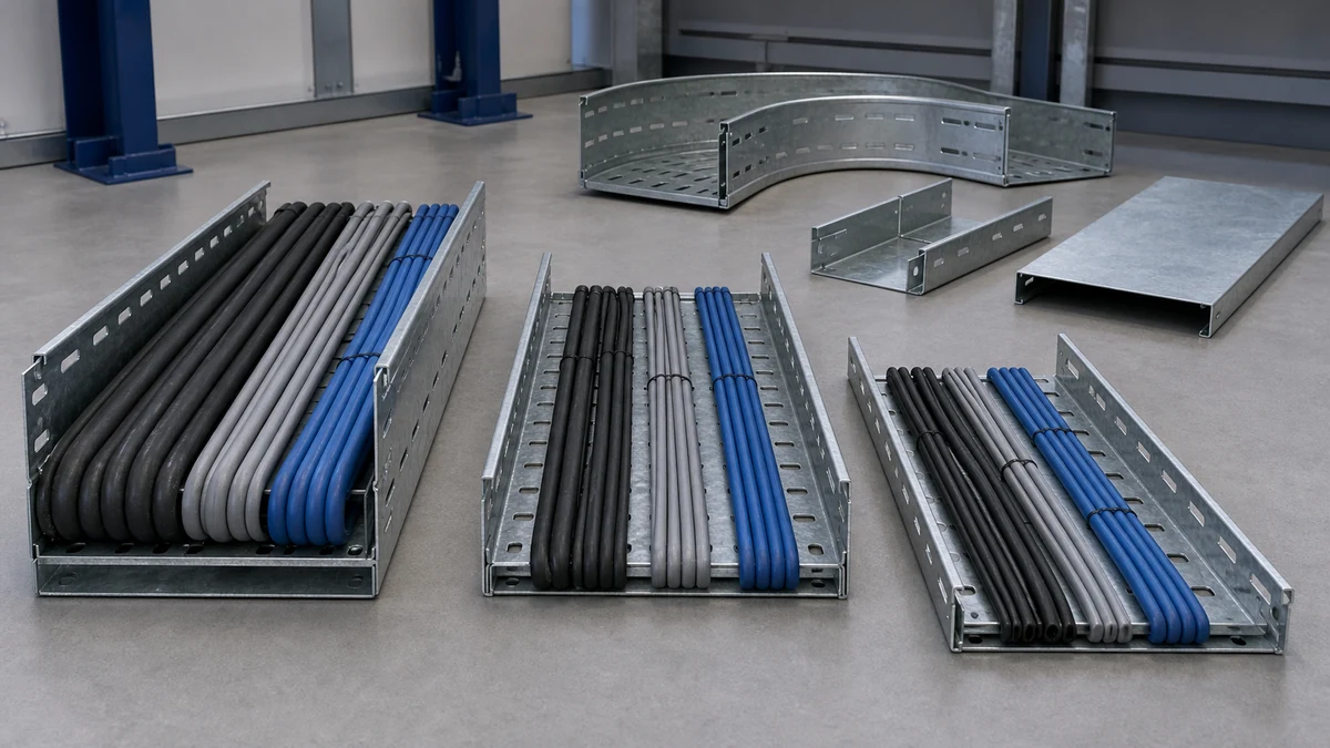
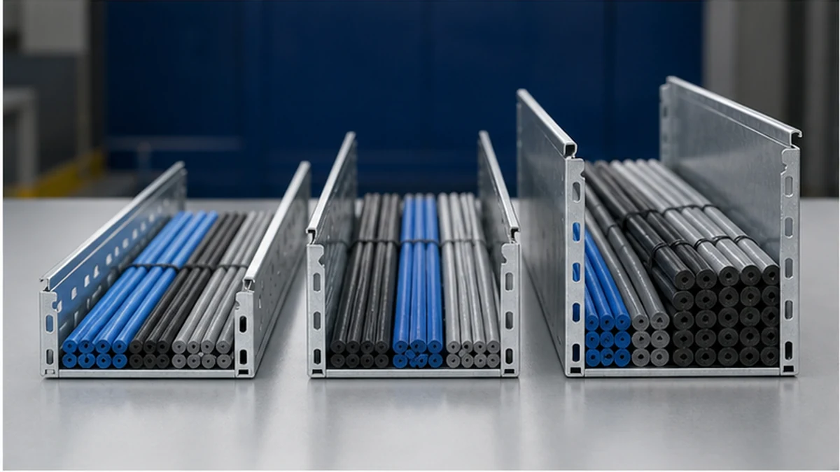
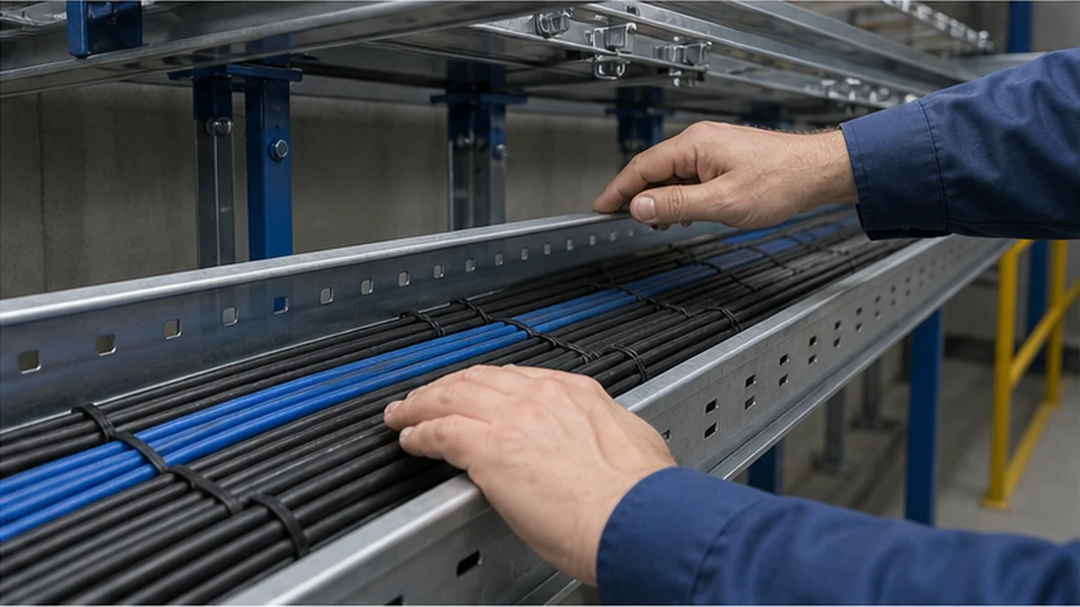
Cable tray depth is the usable sidewall height that retains and organizes the assigned cable assembly. It is frequently summarized as a single capacity number, but that framing is incomplete. The selected depth must work alongside cable outside diameters, permitted bundle arrangement, divider lanes, covers, fittings, access requirements, support positions, and the route’s future-change allowance. A deeper tray creates more containment space in principle, yet it can also affect fitting geometry, cover compatibility, route clearance, and the practical access needed during installation and maintenance. Treating depth as an isolated dimension rather than a system property leads to coordination problems that are difficult to resolve after cable pulling begins.
Establish the tray family, width, material, and fitting range before fixing a side rail height. The full cable tray system range provides a starting point for that selection sequence.
Cable tray side rail height
Build the Route Description Before Selecting a Depth
Depth selection is only as reliable as the input data behind it. Before assigning a side rail height, compile the following for every route segment:
Input
What to Record
Cable schedule revision
Issue date and applicable route segments
Outside diameter per cable
Measured or verified manufacturer value
Quantity per service group
Confirmed against current scope
Required segregation
Service classification and spacing rule
Planned arrangement
Single-layer, controlled multi-layer, or compartmented
Future capacity allowance
Explicit percentage or reserved lane, not a general margin
Fitting nodes
Each elbow, tee, reducer, riser, drop-out, and entry
Cover and divider intent
Required, optional, or excluded per zone
Record the coordination drawing revision alongside each selection. If the cable schedule changes, the route description is the document that triggers a depth review.
Distinguish Nominal Depth from Usable Routing Height
Nominal tray depth shown in a product catalog is not automatically equal to usable cable routing height. Base details, sidewall returns, divider mounting hardware, hold-downs, splice plates, and cover engagement clips can all reduce the clear space available to the cable bundle. At a change in direction, the cable group may occupy more vertical space than it requires on a straight run because individual cables spread or stiffen through the bend radius.
The design calculation should identify the clear routing height separately from the catalog dimension and show the deductions applied. Where a specific accessory occupies part of the sidewall zone, dimension that accessory in the coordinated drawing rather than assuming it fits within the nominal profile.
IEC 61537 addresses cable tray and cable ladder systems as manufactured products. The IEC 61537 publication should be read alongside the project’s electrical installation documents and cable-design specifications. It is not a cable ampacity rule or a segregation requirement, and it should not be cited as the basis for a capacity claim without also stating the applicable project conditions.
Match Side Rail Height to Cable Geometry and Access
Select a side rail height that keeps the approved cable bundle within the intended route while preserving the access needed for safe pulling, tie-down, and inspection. The following factors each warrant a check at the design stage:
Cable bend behavior at elbows, risers, and equipment entries, where cables may press against the sidewall or each other
Layer restraint in multi-layer arrangements, where upper cables may shift during pulling and temporarily exceed the planned bundle height
Divider interaction, including whether cables lean across divider tops when the tray is not fully populated
Tool access, meaning the clearance needed to apply cable ties, clamps, or retainers without damaging cable jackets
Cover removal path, particularly on routes where covers must be lifted rather than slid
Cable retention and future capacity are distinct questions. A route may have adequate physical height for the current bundle but no orderly method for adding cables later. Unused vertical space may also be reserved for a cover transition, a planned divider, or maintenance access rather than additional conductors. Document the purpose of any reserved space explicitly in the route design so it is not reused informally during installation.
Cable tray depth clearance
Apply the Side Rail Depth Decision Table
Use the table below as a structured prompt during the design review. No row produces a final depth independently; each row identifies a condition to verify before the selection is confirmed.
Decision Point
Question to Confirm
If Unresolved
Bundle height
Does the sum of stacked cable ODs, with arrangement factor, fit within usable routing height?
Recalculate with current ODs; do not estimate
Cover clearance
Does the selected cover engage correctly above the cable bundle?
Check cover model against tray model before ordering
Divider lane width
Does the depth allow the divider to create the required lane height?
Confirm divider model fits selected side rail height
Fitting transition
Is depth maintained through all elbows, tees, and reducers on the route?
Identify the governing node and redesign that fitting
Support hardware
Do hangers, brackets, and splice plates clear the cable access zone?
Coordinate hardware positions with the routed bundle
Future allocation
Is reserved capacity documented as a lane, percentage, or explicit exclusion?
Record the basis; do not leave it as a general assumption
Inspection access
Can a technician reach cable ties and retainers with the route populated?
Photograph a representative installed section before full pull
Check the Tray Type and Fitting Family
Side rail geometry behaves differently depending on the tray type. On ladder cable tray, the side rail and rung combination must accommodate the selected cable support method, any divider hardware, and cover mounting without the rung spacing becoming the governing constraint. On a perforated system, the sidewall profile, base perforation pattern, and fitting design together influence how cable groups and accessories are fixed; confirm the selected perforated cable tray profile against the project submittal rather than a generic depth label.
The approved system drawing is the governing reference. A product image or a nominal depth listed in a price schedule does not confirm fitting compatibility or cover engagement geometry.
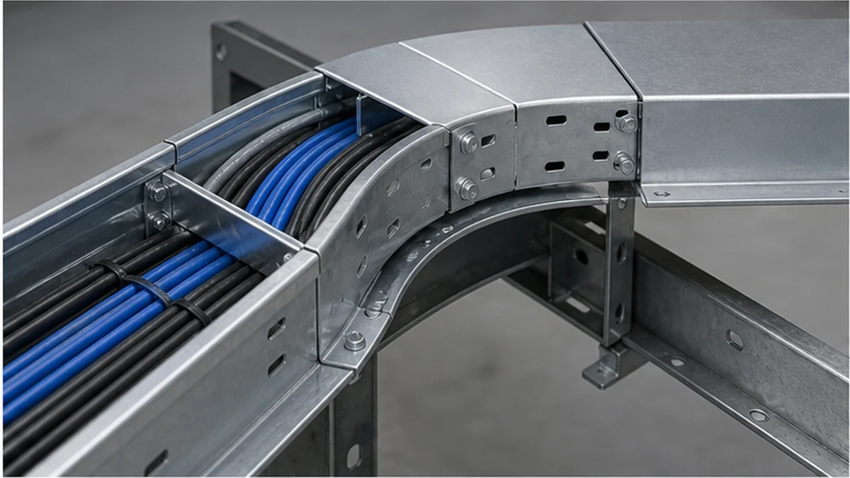
Depth must be maintained continuously through every route node: elbows, tees, reducers, risers, drop-outs, and equipment entries. A taller straight section does not compensate for a reducer or cover transition that creates the governing clearance restriction. Review each fitting node individually and identify any factory fitting, listed accessory, or formally approved adaptation required to keep cable groups controlled and within the planned sidewall height.
For dimensional relationships between width, side height, and cable layout, the cable tray dimensions guide provides planning context. Confirm the exact model, material grade, and fitting geometry in the project submittal before procurement.
Coordinate Covers, Dividers, and Supports
Cover and divider selection cannot be deferred until after the tray depth is fixed. Both interact with sidewall height in ways that affect practical usability.
Dividers: Confirm that the divider model fits the selected side rail height and that the resulting lane heights match the cable groups assigned to each lane. A divider that is shorter than the side rail creates a gap through which cables can migrate. A divider that is taller than the usable routing height may conflict with cover engagement.
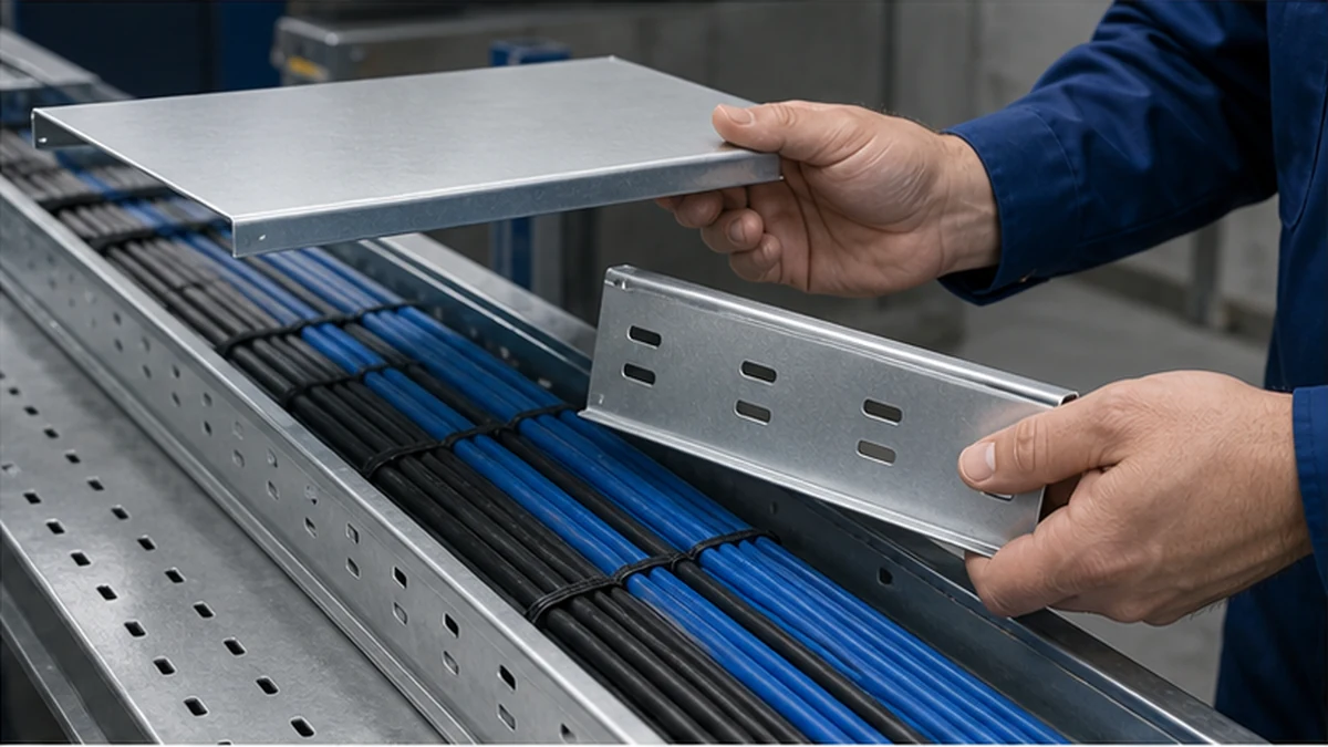
Covers: Verify the cover’s engagement method, clamp clearance, and removal path with the route populated. A cover that cannot be removed after cables are installed prevents maintenance access even if the nominal tray depth appeared adequate at the design stage. Check whether the cover removal requires a specific tool or a minimum clearance above the tray that must be coordinated with structural elements.
Supports: Hanger rods, wall brackets, channel strut, splice plates, and cable cleats can all occupy part of the access zone at a sidewall or fitting. Include those interface dimensions in the coordinated drawing. Inspect a representative installed section before the route is fully populated to confirm that the actual hardware positions match the drawing.
Cable tray depth at fitting
Make Capacity Assumptions Traceable and Revisable
The purchasing and installation package should state the selected width and depth, the usable routing height assumption, the cable groups covered, the permitted future capacity basis, tray type, material, finish, covers, dividers, fittings, and support interface details. Describing a tray as suitable for a particular application without showing the input data and the route condition that was evaluated does not constitute a traceable selection.
When cable quantities, outside diameters, or route geometry change, update the route check and record the revised drawing number. The cable tray size calculation guide offers broader sizing context, but every confirmed selection should cite the current cable schedule revision and coordinated drawing. That link between the selection and its supporting data makes it possible to identify whether the planned side rail height remains valid after scope changes.
Inspect a Representative Route Section Before Full Cable Pull
Before general cable pulling begins, verify the installed tray profile and fittings against the approved coordinated drawing. The inspection should cover the following items:
Measured clear sidewall height against the design routing height
Cable lane arrangement and divider position
Cover engagement, clamp clearance, and confirmed removal path
Access clearance for cable pulling, positioning, and tie-down
Fitting continuity through elbows, reducers, and equipment entries
Support hardware positions relative to the cable access zone
Photograph the representative section and retain the record with the installation package. If a discrepancy is found, resolve it through a formal design query before populating adjacent sections.
Cable tray depth inspection
Approval Workflow for Depth Selection
A structured approval sequence reduces the risk of a depth selection being fixed on incomplete data and then carried into procurement and installation without review.
Route description issued — Cable schedule revision, fitting nodes, segregation requirements, and cover or divider intent recorded
Preliminary depth calculated — Usable routing height established with deductions itemized; fitting nodes reviewed individually
Tray type and model confirmed — Side rail profile, cover model, divider model, and fitting family matched against route description
Coordination drawing reviewed — Support positions, hardware interfaces, and access clearances checked
Design authority sign-off — Selection documented with cable schedule revision, drawing revision, and usable routing height basis
Post-change review triggered — Any change to cable schedule, route geometry, or fitting family reopens steps 2 through 5
Each step should reference the document revision it relied on. That traceability supports site inspection, commissioning checks, and future modifications.
Xinma System Coordination
Xinma manufactures cable tray sections together with the fittings, covers, dividers, busway, and seismic-bracing components that interact directly with side rail height selection. For depth-related coordination, working within a matched Xinma system allows the design team to compare rail profiles, cover engagement models, divider mount dimensions, and fitting geometry using consistent model codes across the BOM. Seismic-bracing attachment points and bracing intervals can be checked against the selected side rail height and support spacing without introducing dimensional conflicts from mixed-supplier components. Site inspection checklists can reference the same model identifiers used in the coordinated drawing, which simplifies pre-pull verification and supports consistent records for commissioning and handover. Xinma’s technical team can support compatibility checks between the tray profile, cover type, and divider configuration before the purchasing package is finalized.
Frequently Asked Questions
Does a deeper cable tray always carry more cable?
Not by itself. Usable capacity depends on width, cable outside diameters, permitted bundle arrangement, fittings, dividers, covers, access clearances, and project-specific requirements. A larger nominal depth figure does not resolve a constraint at a fitting node or a cover engagement conflict.
Is nominal side rail height the same as usable routing height?
Not always. Sidewall returns, base hardware, divider mounting systems, cover engagement clips, splice plates, and installation clearances can reduce the space available to the cable bundle. The design calculation should state usable routing height separately and show the deductions applied.
Should cover selection be checked alongside tray depth?
Yes. The selected cover must engage the tray profile correctly, clear the cable bundle, and allow the planned maintenance access after the route is populated. Cover selection deferred until after tray procurement can create compatibility problems that are difficult to resolve on site.
What most commonly controls depth at a route change?
Elbows, reducers, risers, equipment entries, and cover or fitting transitions frequently set the governing clearance restriction for a route rather than the straight tray section. Each fitting node should be reviewed individually during the design stage.
When should a depth selection be reconsidered?
Revisit the selection when the cable schedule revision changes quantities or outside diameters, when route geometry is modified, when the divider layout or cover requirement changes, when the fitting family is substituted, or when the future-capacity assumption is revised. The design authority sign-off step in the approval workflow is the checkpoint for recording that review.
Kevin Zheng
Kevin Zheng is a manager linked to Shanghai Xinma Busway & Cable Tray Co., Ltd. He writes technical content on cable tray systems, installation practice, sizing logic, load classes, and related standards for industrial and infrastructure applications.