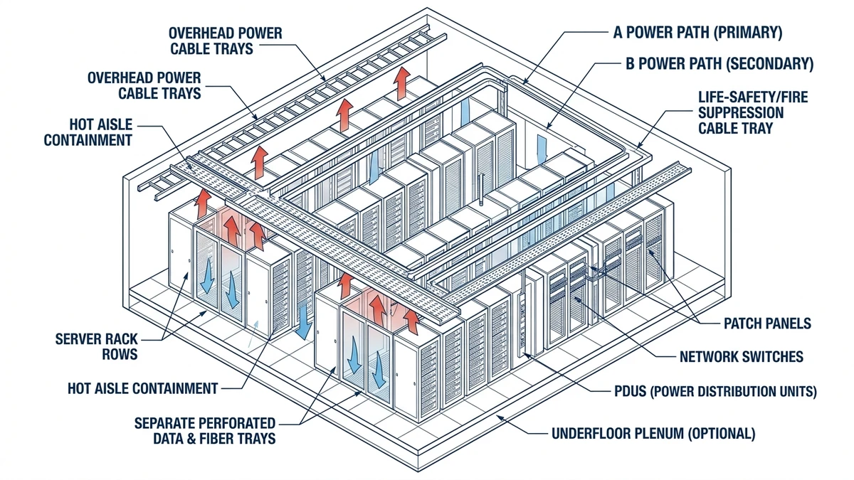
In 2026 data centers, a cable tray is a structural, ventilated cable management system that carries high‑density power and data bundles above white space and in gallery corridors. It controls three things that matter in operation: continuous mechanical support, predictable heat dissipation, and physical segregation between different voltage and signal systems.
Modern data center trays are treated as load‑bearing elements, not just “cable shelves.” A 600 mm ladder tray rated to IEC 61537 Class C might carry 75–150 kg/m at 3.0 m spans while limiting deflection to about L/200, but that still has to be checked against real cable mass—dense power and data bundles can exceed 60 kg/m before any future additions. As a result, trays, supports, and anchors become part of the electrical infrastructure, with their own capacity checks and coordination rules.
For mechanical classification and testing logic, use the IEC 61537 publication page as the standard reference.
Ventilation and thermal behavior
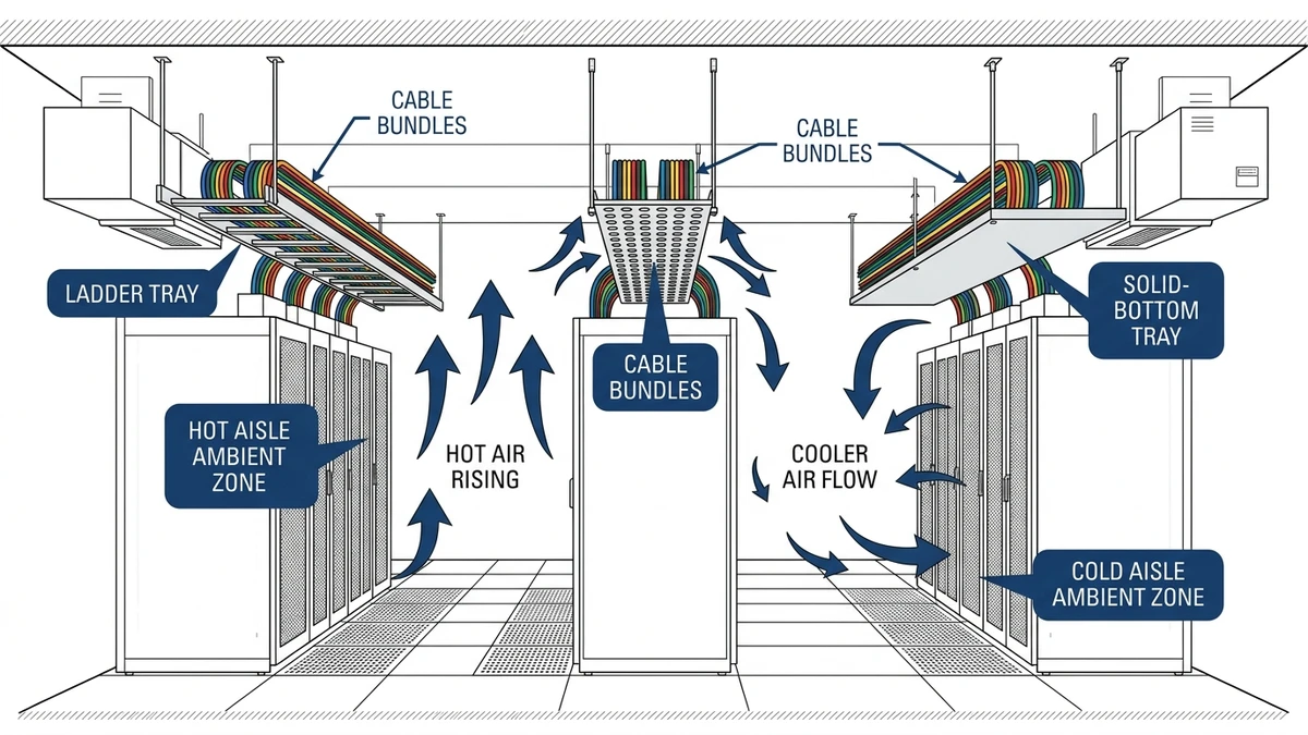
Open ladder and wire mesh trays expose cable surfaces on 3–4 sides, improving convective cooling versus conduit or tightly packed ducts. In hot aisles at 30–35 °C, this often keeps ampacity derating to about 0–10 % instead of 15–20 % for tightly bunched bundles, provided fill stays below roughly 40–60 % of tray width.
When covers or fire barriers are added and fill rises, the tray behaves more like a duct: enclosed‑space derating factors from IEC 60364‑5‑52 must be applied, protective devices re‑checked at higher conductor temperatures, and insulation limits verified. A typical result is that a 240 mm² feeder that runs at 100 % catalog ampacity in open ladder tray may need to be limited to 80–90 % once a solid cover is added and fill exceeds ~50 %.
Segregation and routing logic
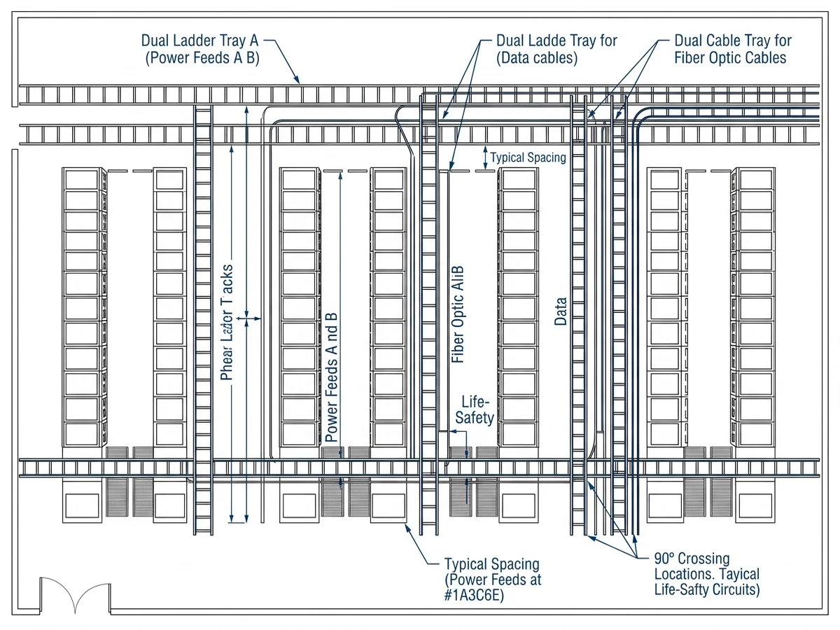
Trays implement electrical segregation as much as they provide mechanical support. Data centers commonly use separate trays for LV power, UPS output, battery strings, and IT/data, maintain 150–300 mm gaps between parallel systems of different voltage or EMC sensitivity, and cross power and data at 90° with vertical separation.
In raised‑floor or ceiling grids, this segregation controls crosstalk risk, simplifies fault investigations, and makes future adds/moves predictable, so it is treated as co‑equal with structural sizing during layout.
Support, restraint, and field conditions
On real projects, support layout often governs more than tray steel strength. Above white space, long straight runs typically use 2.5–3.0 m hanger spacing, but in seismic zones with peak ground acceleration ≥0.2 g, spans are often shortened to 1.8–2.4 m and transverse restraints added so tray, supports, and anchors share inertial loads.
NEMA VE 1 and IEC 61537 define test methods and load classes, but designers still translate those ratings into conservative site rules on fill ratios, tray and cover selection, and support spacing that reflect real cable weight, thermal limits, and local seismic or fire‑rating requirements.
Ventilation and thermal behavior of tray‑mounted cables above IT racks
Cable tray installed above IT racks sits in a mixed thermal environment: hot exhaust plumes from racks (often 35–45 °C) rise into the tray zone, while supply air at 18–24 °C flows mainly below the tray. This vertical gradient directly affects cable insulation temperature and ampacity derating, so the “tray zone” should be treated as its own micro‑environment rather than assuming room setpoint conditions.
Buoyancy, stratification, and the plume zone
Hot air leaving rack exhausts at roughly 1–3 m/s is buoyant relative to room air, creating a thermal plume 0.5–1.0 m above rack tops where temperatures can be 5–12 K higher than room setpoint. If ladder or wire tray sits in this plume—e.g., tray centerline 300 mm above racks—cables can see 32–35 °C in a 24 °C room, cutting thermal margin and typically requiring 5–15 % derating compared with “free air at 30 °C” tables.
With hot‑aisle/cold‑aisle containment, trays crossing over hot aisles can see even higher local temperatures, especially below slabs or ceilings that trap heat and slow mixing.
Tray geometry and cable heating
Above racks, tray type strongly affects cable temperature. Ladder tray with 100–200 mm rung spacing allows vertical convection and plume wash‑through, so cable surface temperature closely tracks local air, while solid‑bottom or heavily filled wire tray restricts convection and adds 3–10 K from I²R losses.
In commissioning, it is common to measure 50 mm² feeders in solid tray running 10–15 °C hotter than identical feeders in ladder tray over hot aisles at similar fill, which can be enough to shift a circuit from acceptable to marginal in protective device studies.
Design consequences above IT racks
For trays above racks, practical rules are: assume tray‑level ambient is 5–10 K above room setpoint unless CFD or measurements show otherwise, prefer ladder or wire tray over solid‑bottom for high‑load power circuits in the plume zone, increase vertical separation where possible to move out of the hottest plume core, and verify ampacity using “cables in free air” tables with additional factors for elevated ambient and grouping.
Figure 1. Ventilation comparison of ladder, perforated, and solid cable trays installed above hot and cold aisles, with airflow and temperature zones indicated.
Segregation of power, network, and life‑safety routes in data halls
In data halls, tray segregation is driven by clearances, access, and fault behavior as much as tidy drawings. The objective is that a fault or maintenance event in one tray route does not jeopardize IT traffic or life‑safety systems sharing the same space.
Typical elevation and zoning patterns
Most Tier III/IV layouts use three vertical “bands” over white space: power distribution on overhead ladder trays at around 2.7–3.2 m, typically in hot‑aisle zones; network trays (often wire mesh or ladder) horizontally offset ≥300 mm and centered over cold aisles; and life‑safety/BMS trays at the highest elevation or along walls, clear of dense power bundles. Keeping 300–600 mm horizontal separation between >400 V power and network trays aligns with EMC segregation guidance in IEC 60364‑5‑52 and simplifies inspection.
Field rules for tray grouping and crossing
On site, a common, inspection‑friendly pattern is to group large feeders and UPS outputs on dedicated power trays, keep branch power on separate trays with at least 150 mm vertical separation, route CAT6A/optical trays so they cross power at 90° with ≥200 mm vertical offset, and keep fire alarm, voice evacuation, and emergency shutdown cables in trays that do not share supports with non‑life‑safety routes within 1.0 m.
This approach limits inductive coupling, avoids overloading shared supports when heavy power bundles are added, and makes segregation violations easy to spot during walk‑downs.
Life‑safety survivability zones
For life‑safety trays, survivability under fault or fire is key. They are usually routed along structural walls or columns instead of over hot aisles, kept away from “waterfalls” of power ladder dropping from power rooms, and limited to 10–15 m of co‑routing within 300 mm of high‑density power trays. A simple design check is whether a busway or power ladder failure would do more than local mechanical damage to the life‑safety tray in the same zone; if so, the route should be revised.
Figure 2. Plan view of a data hall showing dual A/B power ladders, separate data/fiber trays, and isolated life-safety tray with recommended spacing and crossing geometry.
Support logic: spans, loading, and coordination with structure
Support logic for data center trays starts with span selection that gives acceptable deflection and reserve capacity under realistic cable loads, then aligning those spans with structure, seismic bracing, and access needs.
Load‑to‑span reasoning in practice
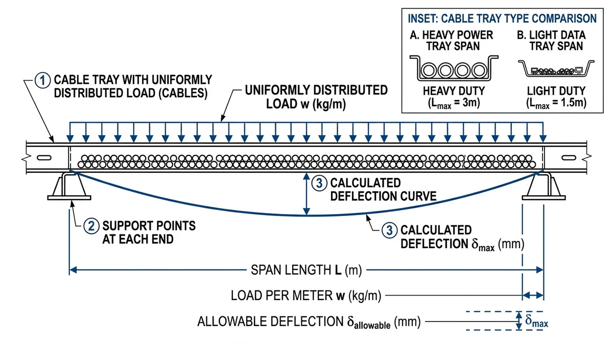
Estimate the final distributed load, including future growth: a 600 mm tray carrying power and data often ends up at 40–80 kg/m cable weight once white space is fully built out, plus 5–12 kg/m of tray and any covers. IEC 61537 and NEMA VE 1 provide load classes at defined spans; if your span is shorter than the test span, catalog ratings usually apply with a safety factor, but if it is longer, deflection increases sharply and spans or tray class must be adjusted.
As a working rule, 300–450 mm trays with moderate fill can usually run at 2.5–3.0 m spans, while 600–900 mm trays with dense power bundles often need 1.8–2.4 m spans to keep deflection around L/200. Tightening heavily loaded power runs by about 0.5 m typically cuts mid‑span sag by 30–40 %, reducing jacket damage risk and ad‑hoc “fixes” in the field.
Coordination with structure and other systems
Support points must tie back to structural steel, concrete inserts, or pre‑planned strut grids and avoid clashes with other systems. Common conflict points are column lines where beam directions change, hot/cold aisle containment frames that constrain elevation and clearance, and seismic bracing locations that demand clear load paths.
A robust workflow is to fix critical elevation bands over racks and under major ductwork, lay out a regular support grid (e.g., 2.4 m) aligned with primary beams and inserts, and then add local adjustments near penetrations, drops, and direction changes, with supports typically placed within 300–600 mm of T‑pieces and risers. In containment corridors with large copper power cables, many teams also tighten spans and upgrade hardware to improve long‑term sag and seismic performance.
Figure 3. Structural diagram of a cable tray span with uniformly distributed cable load, support spacing, and deflection arrow illustrating span-to-load relationships.
Applying these design trade‑offs with Xinma in a real specification
By detailed design, choices on tray type, ventilation, segregation, and spans already influence ampacity, EMC performance, and structural loading, and changes in one area often force adjustments elsewhere. Involving Xinma as a system partner at this stage turns these interactions into managed engineering decisions rather than late procurement issues.
A few typical consequences where manufacturer input helps:
Covers and perforation patterns
Moving from open ladder to covered or solid tray can raise cable operating temperature by 5–15 °C by reducing convection and increasing local ambient, leading to 10–25 % ampacity derating and possibly requiring larger conductors, wider trays, or more parallel runs.
Segregation and barriers
Metallic dividers between power and control improve EMC but reduce usable tray width; for example, a 300 mm ladder with a 50 mm barrier can behave like two ~200–220 mm trays at realistic fill, which may force a step up to a wider tray to avoid overpacking.
Support spans and load classes
Tightening spans from 3.0 m to 2.0 m in dense areas may push a run toward IEC 61537 Class D expectations, implying heavier rails, stronger fittings, and upgraded supports, but it also recovers margin for future cable additions without structural rework.
Xinma’s engineering team can validate tray type and load class against the cable schedule and growth assumptions, confirm fault‑current withstand and mechanical performance of fittings at high‑load areas, review derating assumptions for trays above hot aisles versus cooler galleries, and coordinate support layouts with building structure and seismic schemes where required.
Sharing a one‑line tray routing plan and preliminary cable schedule around the 30–60 % design stage allows Xinma to help refine the cable management system as a coordinated package rather than react to a frozen layout. For tray families and behavior in real installations, see Xinma’s cable tray product overview and ladder‑type tray specifications; for projects where fire or contamination control favors solid or perforated designs, compare thermal and derating implications against the perforated tray series.
This article has been updated with explicit source and procurement checks so engineering, EPC, and purchasing teams can verify the recommendations instead of relying only on generic product descriptions. For project use, treat the table below as a starting evidence map and confirm the final requirements against local codes, consultant drawings, and supplier submittals.
Use this source to verify standards, product scope, installation assumptions, or supplier evidence before final specification.
Buyer Verification Checklist
Request drawings that show tray width, depth, side rail profile, bend radius, fittings, and support spacing.
Ask for load tables or engineering assumptions that state test span, load class, and deflection criteria.
Confirm material grade, surface finish, coating method, and corrosion exposure assumptions before comparing prices.
Check whether accessories such as covers, couplers, reducers, clamps, grounding jumpers, and brackets are included.
For EPC or export orders, review packaging, labeling, inspection records, and drawing revision control before shipment.
Frequently Asked Questions
How do I size cable trays for high‑density data center runs?
Start from the fully built‑out cable mass and target fill ratio: keep working fill around 40–60 % of tray width, then check that the resulting distributed load stays within the tray’s tested load class at your chosen span, adjusting either tray width or span if you exceed deflection or loading limits.
Where should I avoid using solid‑bottom cable trays in a data hall?
Avoid solid‑bottom trays directly above hot aisles or close to rack exhaust plumes, because restricted convection can raise cable temperature by more than 10 °C, which often increases derating and may force upsizing of conductors or additional parallel circuits.
How much separation is usually enough between power and data trays?
In most data center layouts, 300–600 mm horizontal separation between trays carrying >400 V power and trays carrying network or control cables is used, combined with 90° crossings and vertical offsets at intersections to reduce inductive coupling and simplify EMC compliance.
What span should I use for heavily loaded 600 mm ladder trays?
For 600 mm trays carrying dense power and communication bundles, spans in the range of 1.8–2.4 m are typically selected so that combined cable and tray weight keeps mid‑span deflection near or below L/200, with reserve capacity for future additions.
When does it make sense to add metallic barriers inside a tray?
Barriers are useful when power and sensitive control or signaling cables must share a tray, but they should be specified when EMC benefits justify the loss of usable width and possible increase in tray size, and only after checking that each side can still meet fill and load limits.
How early should a tray manufacturer be involved in a new data center design?
Engaging a manufacturer around the 30–60 % design stage is usually effective, because tray type, span strategy, and segregation schemes are defined enough for meaningful review but still flexible enough to adjust before issuing construction documents.
Kevin Zheng
Kevin Zheng is a manager linked to Shanghai Xinma Busway & Cable Tray Co., Ltd. He writes technical content on cable tray systems, installation practice, sizing logic, load classes, and related standards for industrial and infrastructure applications.