Video overview: key engineering checks before selecting this cable tray system.
What Is Cable Tray Support Distance?
Cable tray support distance is the center-to-center spacing between supports that a tray spans under a stated load, typically about 1.5 m to 3.0 m for standard systems. For buyers and specifiers, that number only matters when tied to tested load, tray width, and deflection performance under standards such as IEC 61537 and NEMA VE 1.
Support distance is a key selection input because span affects bending stress, midspan deflection, splice loading, and hanger reaction. A tray that works at 1.5 m may be under-rated at 3.0 m even if width and cable load stay the same.
The common mistake is choosing by tray form or thickness alone. The better question is: what load can this system carry at the actual support spacing available on site, with acceptable deflection and fitting support?
A useful starting framework is:
Set the real support spacing available from structure, in m.
Calculate total distributed load in kg/m: cables, tray self-weight, and accessories.
Check whether covers, fittings, maintenance loads, or future fill change the design basis.
Select the tray system by tested span/load performance, not width alone.
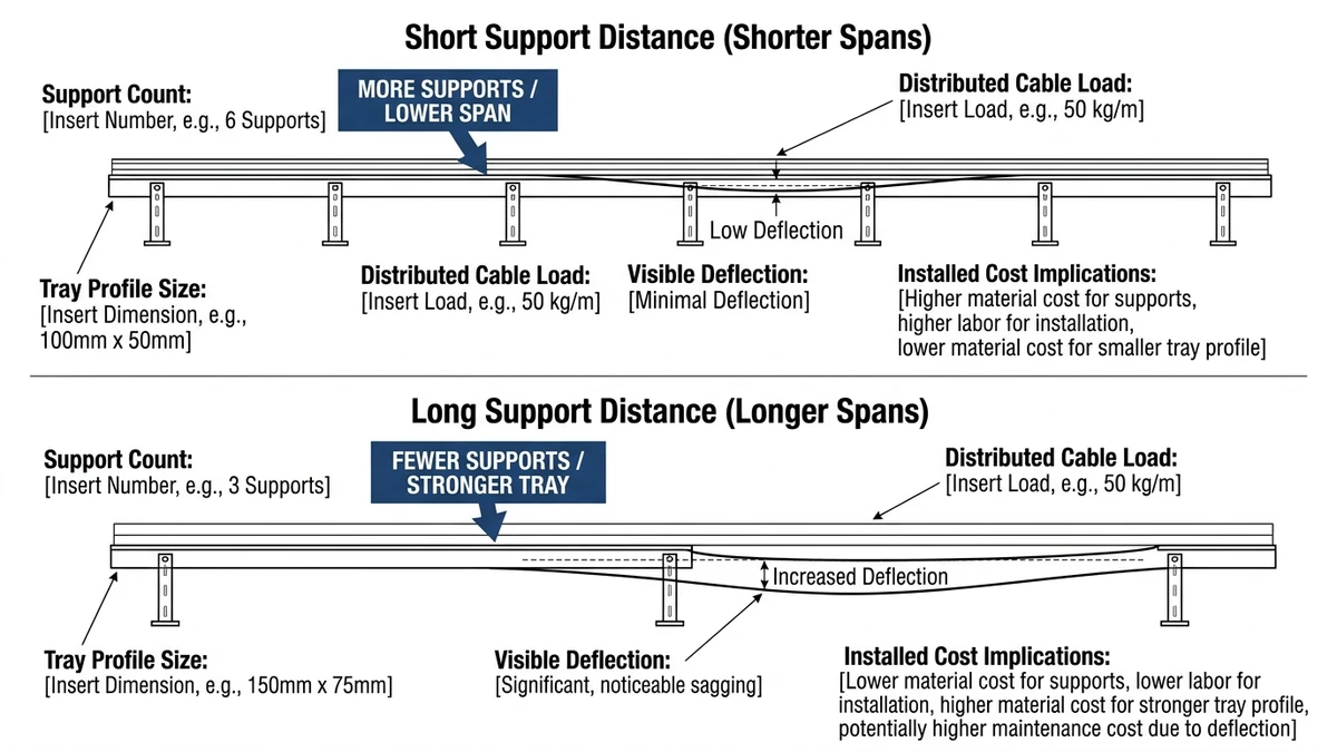
For example, a light wire basket carrying 25-40 kg/m over 1.2-1.8 m may suit control and data routing. A ladder tray carrying 75-150 kg/m of power cables often needs deeper side rails, stronger splice locations, and support centers closer to 2.0-3.0 m depending on width and deflection limits.
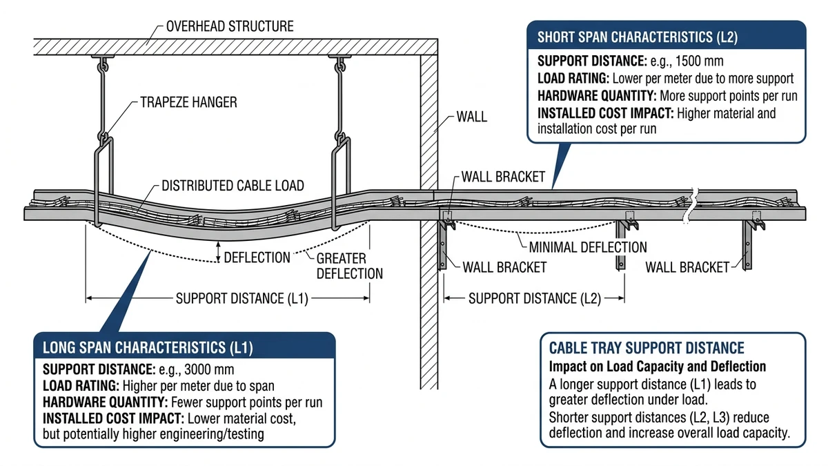
Figure 1. Comparison of shorter and longer cable tray support spans, highlighting effects on support quantity, tray strength, and installed cost.
What Determines the Correct Cable Tray Support Spacing?
The correct cable tray support spacing is set by four variables: total load, tested span rating, allowable deflection, and installation condition. There is no single “standard distance” for every route.
Load first: present load and future fill
Support spacing starts with uniformly distributed load in kg/m, including tray self-weight, cable weight, and any realistic future fill. If future cable growth may exceed about 20%, design to the future load case instead of the day-one load.
Span rating and deflection limit
IEC 61537 covers mechanical test principles for cable tray and cable ladder systems, including load and deflection behavior. See the IEC publication page here.
A span claim only has meaning when paired with tested load and deflection criterion. A common working check is around L/200, subject to project requirements and supplier test basis.
Tray geometry and fittings
Tray width and rail depth change performance. Two trays with the same width can carry different loads at the same span if one has deeper or stiffer side rails.
Fittings also need separate attention. Horizontal elbows, tees, reducers, and vertical bends are not equivalent to straight sections, so supports are often placed within about 300-600 mm of major fittings unless the manufacturer states otherwise.
Environment and restraint
Outdoor runs, corrosive areas, rooftops, and seismic zones often reduce usable support spacing because wind uplift, dust, snow, thermal movement, and lateral restraint affect the support system. Vertical tray capacity alone is not enough if brackets, anchors, or bracing are underdesigned.
[Expert Insight]
If structure limits support points, treat that as a tray selection issue early.
For rooftop runs, check uplift and cover weight together.
If future cable growth is likely to exceed about 20%, design around the future load case.
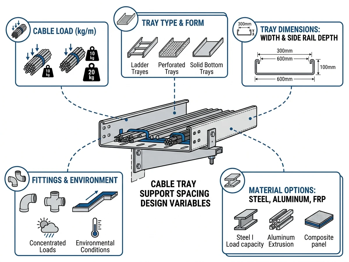
Figure 2. Key variables governing cable tray support spacing, including loading, tray geometry, material, fittings, and environmental conditions.
Typical Support Distance Ranges Buyers See in 2026
Buyers in 2026 still see support distance grouped into familiar bands, but these are only first-pass ranges. Tray type, stiffness, width, load in kg/m, and deflection criterion must be reviewed together.
Tray type / duty level
Typical support distance range
Common application
Selection consequence
Light wire tray / basket
1.2-1.8 m
Data, control, low-mass cabling
Good access and low weight, but span drops quickly with bundled cables or wide baskets
Perforated cable tray, light-to-medium duty
1.5-2.0 m
Building services, mixed power/control
Better containment than basket, but covers and outdoor use can force closer supports
Ladder cable tray, medium duty
1.8-2.4 m
Plant rooms, utility corridors, power runs
Better span efficiency for heavier cables; width and fitting loads still need checking
Ladder cable tray, heavy duty
2.4-3.0 m
Industrial mains, heavier feeders
Suitable where structure gives fewer support points, but only with verified load class data
Special long-span cable ladder
3.0-6.0 m
Process plants, crossings, limited fixing points
Usually requires project-specific structural review of deflection, splice behavior, and restraint
Reading these ranges correctly
A catalog span such as 3.0 m only applies to a stated load and support condition. For example, a 300 mm tray carrying 25 kg/m may work at 2.4 m centers, while the same series at 600 mm width and 50 kg/m may need supports closer to 1.5-1.8 m.
Engineering comparison: shorter span versus heavier tray
Use shorter support spacing when loads are uncertain, future fill is likely, or covers, rooftop exposure, and seismic requirements add demand. Use a heavier tray at longer spans when support points are limited and the manufacturer provides tested load/span data for the exact tray family.
Do not assume one heavier size always solves a long-span problem. In some cases, the better move is changing tray category, such as from shallow perforated tray to ladder tray for better structural efficiency.
How to Compare Supplier Quotes for Support Distance
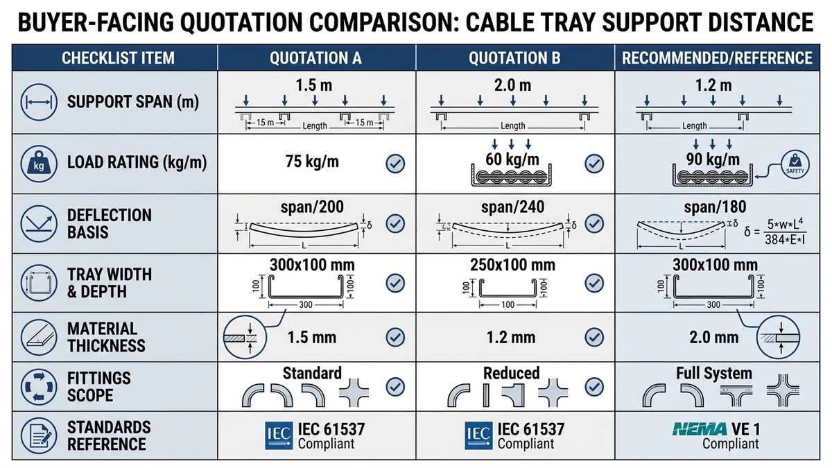
When supplier quotes list the same support distance, they may still represent different structural performance. Compare them on a normalized basis: same width, same load, same material, same deflection criterion, and same scope.
Normalize the quote before comparing price
Check each quote against the same variables:
stated support spacing in m
tray width and side rail height in mm
material and thickness in mm
distributed load basis in kg/m or N/m
whether tray self-weight is included
deflection criterion used for rating
fitting rating versus straight-run rating
included supports, brackets, clamps, anchors, and fasteners
treatment of cover weight, wind, corrosion, and thermal movement
exclusions for point loads or concentrated loads
A 3.0 m span at 50 kg/m with no deflection basis is not equivalent to a 3.0 m span at 75 kg/m with stated L/200 and included supports.
What often gets missed in low-price quotes
The biggest gaps are often outside the tray body itself. Supports may be omitted, fitting supports left undefined, or cover weight excluded, which can force redesign once detailing starts.
Use when / avoid when / check before specifying
Use a longer-span quote when:
– test data matches your tray width and load case
– fitting details are rated or detailed for the same system
– support hardware is included and reaction loads are clear
Avoid relying on a longer-span quote when:
– deflection criteria are not stated
– only straight sections are rated
– the route contains many tees, bends, or rooftop sections
– the supplier excludes supports or accessories from structural responsibility
Check before specifying:
– whether spans are based on uniformly distributed load only
– whether splice locations are constrained
– whether heavier covers or barriers were included
– whether the support plan changes for wide trays or seismic restraint
A practical example: if Quote A supports 3.0 m at 75 kg/m with stated deflection control and Quote B supports 3.0 m at 50 kg/m with no clear deflection basis, Quote A is usually the safer baseline even if unit price is 8-12% higher.
Figure 3. Buyer comparison checklist for cable tray support distance, covering span, load rating, deflection basis, materials, fittings, and standard references.
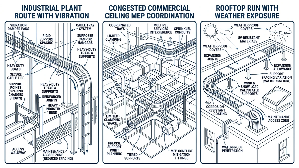
Where Field Conditions Change the Support Plan
Catalog spans often change once the route is built. Field conditions can add eccentric loading, vibration, thermal movement, and access limits that alter the support plan.
Heavy cable runs and wide trays
As load rises into roughly 80-120 kg/m, deflection and splice demand increase, especially on wide ladder trays. A 600 mm or 900 mm tray can also see temporary torsion during staged cable pulls, so a span that works for balanced final load may still be poor during installation.
Outdoor runs and vibration sources
Roof routes and exposed pipe racks add cover weight, wind suction, snow or dust buildup, and thermal movement. Near compressors, cooling towers, or other vibration sources, shorter spans and better restraint details usually perform better than simply choosing thicker tray material.
Fittings, drops, and transitions
Bends, tees, reducers, and vertical drops interrupt load flow and often need local support control. A support within about 300-600 mm of a major fitting is common practice unless manufacturer details say otherwise.
[Expert Insight]
If your route includes vertical drops, review concentrated mass at the transition, not just horizontal span.
For phased installations, ask how the tray behaves before all cables are in place.
In corrosive areas, match support finish to tray environment.
Figure 4. Field conditions such as vibration, rooftop exposure, congestion, and vertical transitions often require localized support spacing changes.
How to Specify a Coordinated Cable Tray System Instead of a Tray Only
A sound specification should treat tray, fittings, supports, accessories, and loading assumptions as one coordinated system. That is the most reliable way to keep support distance meaningful through procurement and installation.
Specify mechanism, range, and consequence
Instead of vague notes, write requirements that connect loading and support behavior to project decisions:
State the design load in kg/m, including tray self-weight, cable load, and accessory load.
State the intended support spacing range in m and whether support points are fixed by structure.
Require tested or published load/span data for the tray family at the specified width.
State the project deflection criterion or approval basis.
Call out supports near fittings, vertical transitions, and other non-straight sections.
Require support hardware, anchors, and restraint details to be coordinated with tray reactions.
Before issuing a bill of materials or tender package, check three things:
Does the selected tray still work when future fill, covers, and fittings are included?
Are support reactions and bracket types aligned with the available structure?
Are the straight-run spacing rules different from fitting support rules in the specification?
For projects moving into detailed execution, a review against the installation planning guide often catches support conflicts before they show up on site drawings.
Xinma’s role in system coordination
Xinma’s role is most useful when the project needs coordination rather than a tray-only price. Typical changes that trigger rework are width increases, added covers or barriers, and bends or tees that need local support near the fitting throat.
If you are finalizing a specification, Xinma can help review whether the selected tray family, fittings, and supports remain coordinated at the intended spacing. The goal is to reduce redesign risk when load assumptions, structure, and routing details start interacting.
Frequently Asked Questions
How do I choose the right cable tray support distance for a heavy power cable run?
Start with total distributed load in kg/m, then check the tray’s tested span/load data at the actual width and support condition. For heavier power runs, fittings, covers, and future fill often push the design toward shorter spacing or a deeper ladder tray.
Is a 3.0 m cable tray support span considered standard?
It is common in medium- to heavy-duty ladder tray applications, but it is not a default value for every tray system. The acceptable span depends on load, width, stiffness, and the deflection basis used by the supplier.
Why do fittings need supports closer than straight tray sections?
Bends, tees, and reducers change load path and can introduce local torsion or higher joint stress. Supporting them closer to the fitting helps limit movement and reduces demand on splice regions.
Should I size support spacing for current cables or future expansion?
If expansion is likely, it is usually better to evaluate support spacing against the future load case rather than the initial cable fill. That tends to reduce later sag, support retrofits, and coordination changes.
What should I check first when comparing cable tray supplier quotes?
Normalize the quote to the same width, load basis, material thickness, and deflection criterion before comparing price. If those variables are not aligned, span claims can look similar while representing different structural margins.
Do outdoor cable tray runs need different support spacing?
They often do, because wind, cover weight, snow, dust, and thermal movement can change support reactions. Even when tray section capacity is adequate, the bracket and anchor arrangement may need closer spacing or stronger restraint.
Can wider cable trays use the same support spacing as narrow trays?
Not necessarily. As tray width increases, deflection and torsional sensitivity often increase as well, so a support layout that works for a 150 mm tray may not be appropriate for a 600 mm tray under the same load philosophy.
Kevin Zheng
Kevin Zheng is a manager linked to Shanghai Xinma Busway & Cable Tray Co., Ltd. He writes technical content on cable tray systems, installation practice, sizing logic, load classes, and related standards for industrial and infrastructure applications.