Address
304 North Cardinal St.
Dorchester Center, MA 02124
Work Hours
Monday to Friday: 7AM - 7PM
Weekend: 10AM - 5PM
Address
304 North Cardinal St.
Dorchester Center, MA 02124
Work Hours
Monday to Friday: 7AM - 7PM
Weekend: 10AM - 5PM
Get premium quality cable management systems directly from the manufacturer.
Fill out the form below to receive our catalog and pricing.
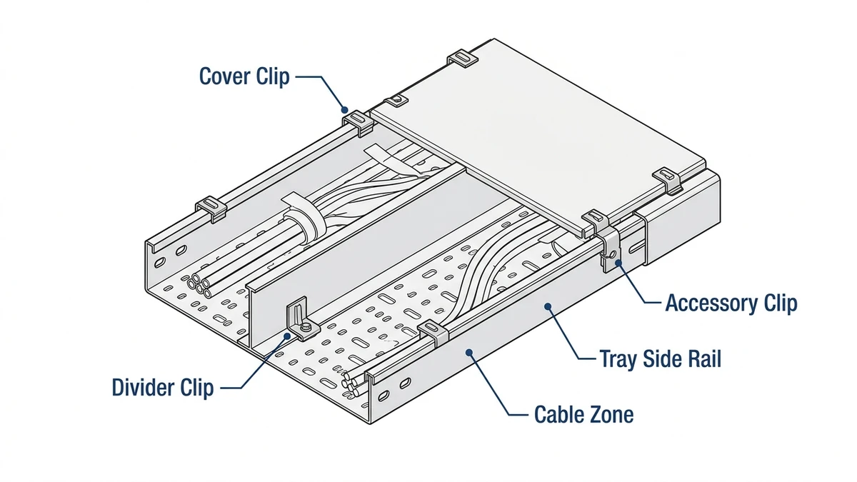
Cable tray clips are small retention components used in cable management systems to secure covers, dividers, bonding parts, accessories, or, in some cases, cables to a cable tray or cable ladder. They do not usually carry the primary tray load. Their job is local restraint: controlling vibration, uplift, movement, continuity, and access reliability across support spans that are often 1.5 m to 3.0 m, which matters when checking system performance under IEC 61537 and NEMA-style installation practice.
A clip looks minor on a drawing, but in service it often determines whether a route stays quiet, bonded, accessible, and intact after thermal cycling and repeated maintenance.
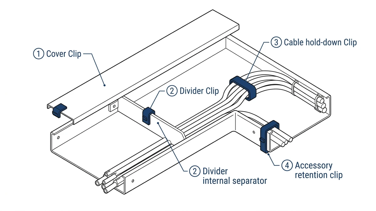
Clip selection should start with function, not shape. In most projects, cable tray clips fall into five working categories—retaining clips, joining clips, cover clips, bonding clips, and divider or accessory clips—and each addresses a different failure mode.
Retaining clips hold cables where movement is expected, such as vertical runs, side-mounted trays, and vibration-prone industrial routes. Typical spacing is about 300 mm to 600 mm, depending on cable size, orientation, and expected movement.
Use them when cable displacement could damage sheaths or alter separation, but do not treat them as structural supports. The key checks are cable diameter range, release method, spacing on risers, and whether the clip edge can mark softer jackets.
Joining clips connect tray lengths or fittings where the manufacturer uses a clip-based connector instead of, or alongside, bolted splice details. Their function is usually alignment and local continuity, not automatically full structural transfer.
If the connector is only positional, bending load still has to be controlled by support location and joint detailing. Before specifying, confirm whether the connector is load-rated, how it behaves at fittings, and whether it contributes to electrical continuity.
Cover clips hold tray covers against uplift, vibration, and accidental displacement, especially on outdoor routes, roof runs, and machinery areas. Their main job is to stop repeated micro-movement from loosening the cover edge over time.
Higher retention force improves security but slows access during inspection and cable changes. For example, a 600 mm-wide outdoor ladder tray may be structurally sound yet still suffer cover rattle or local uplift if clips are missing or weak.
Bonding clips are used where the metallic cable routing system contributes to protective bonding or continuity across tray sections and covers. Here the critical issue is contact resistance across the assembled system, not just the clip itself.
If continuity depends on a clip biting through coatings, finish thickness, corrosion, oxide formation, and installation torque all affect long-term performance. IEC 61537 treats cable tray and ladder systems as assemblies, so continuity should be reviewed at system level using the IEC 61537 publication page as the primary standards reference.
These clips secure dividers, edge protection strips, and light accessories in wire basket, perforated, or ventilated tray systems. Their main role is segregation, abrasion control, and route organization.
They matter where power and control separation affects EMC or maintenance, but they should not be treated as cable-restraint hardware in vibration-prone or vertical conditions. The practical rule is to choose the clip by the failure mode being prevented—movement, separation, uplift, continuity, or segregation.
[Expert Insight]
Cable tray clips matter because they preserve system geometry and serviceability under real operating conditions. A failed clip usually does not collapse a tray; it more often loosens a cover, shifts a divider, breaks continuity, creates noise, or slows every maintenance visit.
During installation, the main issue is local force concentration. If clip spacing is too wide, covers and accessories can lift under wind, airflow, vibration, or cable pulling; pulling forces around 200 N to 500 N can also shift unsecured dividers and drop-out accessories.
Over-tightening creates another risk by damaging zinc or polymer coatings and exposing base metal. In damp or coastal environments, that small damage often becomes the first corrosion site even while the tray body remains sound.
Maintenance teams usually notice clip problems first because missing or loose clips delay access, create nuisance noise, and force covers or fittings to be re-seated before inspection. On plant routes, cover chatter during startup is often traced to retention hardware rather than tray span resonance.
Exposure also changes long-term performance. On routes cycling between about 5 °C and 45 °C, clips may seize, lose spring force, or corrode at mixed-metal interfaces if compatibility was not checked.
The design lesson is not simply to add more clips. It is to place the right clip, at the right spacing, in the right environment.
Tighter spacing helps where vibration or vertical cable movement dominates, while corrosion-resistant and removable designs matter where inspection frequency is high. Bad clip choices usually show up later as slower access, repeated callouts, and accessory failures at the easiest points to service.
[Expert Insight]
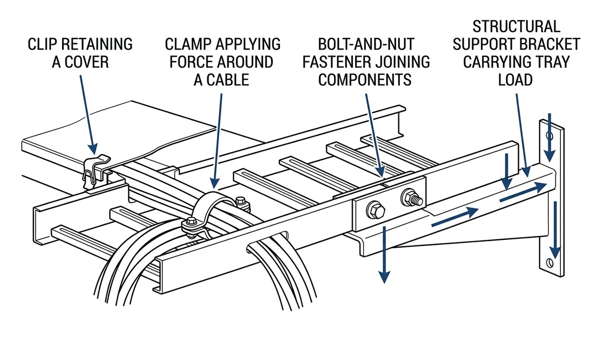
Cable tray clips are often confused with clamps, general fasteners, and supports, but they are not interchangeable. The engineering distinction is the load path: clips provide local retention, while supports carry span loads, fasteners transfer joint loads, and clamps grip by compression.
| Component | Primary function | Typical load resisted | What it connects | Design consequence |
|---|---|---|---|---|
| Cable tray clip | Retains covers, dividers, accessories, or local hold-down parts | Light local shear, vibration, uplift; generally not primary span load | Tray rail, cover edge, divider, accessory bracket | Select for fit, vibration resistance, corrosion class, and maintenance access |
| Clamp | Grips an item by compression | Pullout resistance, local holding force, sometimes cable restraint | Cable bundle, conduit, flange, pipe, or edge | Check grip range in mm and jacket damage risk |
| Fastener | Creates a bolted, screwed, or riveted joint | Tension and shear at the joint | Splice plates, brackets, clips, supports | Joint performance depends on fastener grade, hole tolerance, and torque |
| Support | Carries dead load, cable live load, and environmental action | Bending, shear, anchor load, seismic or wind effects | Hangers, cantilevers, trapezes, wall brackets | Governs span, deflection, and anchor design |
Many specification errors come from blurring these roles. A clip may stop a cover from lifting, but it does not replace a structural splice, support arm, or hanger rod carrying 50 kg/m to 100 kg/m of tray load.
On an outdoor ladder tray with covers, clip selection addresses retention and access, splice fasteners address joint transfer, and supports address tray mass, cable mass, span, and deflection. Mixing those functions leads to loose accessories or overstressed joints.
Use clips for accessory retention, cover security, divider attachment, and local restraint. Use clamps when controlled compression is needed over a defined range, often about 10 mm to 40 mm; use fasteners when the joint must transfer repeatable tension or shear; use supports when the real issue is span, anchor pullout, deflection, seismic restraint, or total loading.
Avoid asking clips to solve structural problems. Before specifying, confirm which part carries the load, which part only retains accessories, and whether the manufacturer’s tested assembly reflects that distinction.
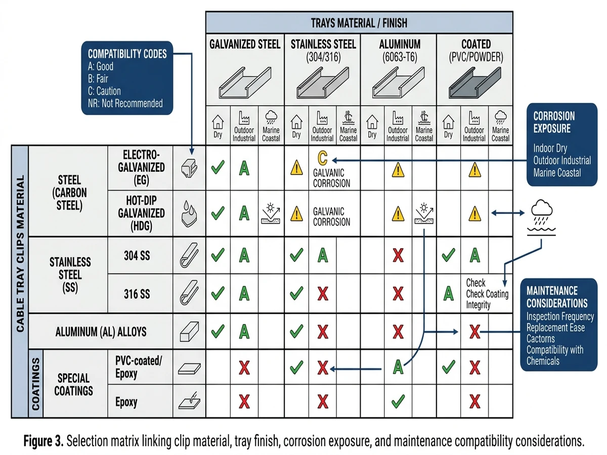
Cable tray clips should be specified as part of the cable management system, not treated as generic hardware. Good selection follows a simple sequence: mechanism, environment, compatibility, then maintenance consequence.
Start with tray material: pre-galvanized steel, hot-dip galvanized steel, stainless steel, aluminum, or FRP. Similar or compatible materials generally reduce galvanic risk, especially where moisture remains on the route.
In dry indoor service, zinc-coated steel clips may be enough; in washdown, chloride, or condensation-prone environments, 304 or 316 stainless steel is often more suitable. Temperature also matters, because polymer inserts may be limited to about 85 °C to 105 °C, while all-metal clips usually tolerate higher conductor-surface temperatures.
A finish name alone does not predict service life. What matters is how the small fixing behaves at cut edges, contact points, and damaged coating areas over the expected inspection interval.
Electroplated finishes may suit clean electrical rooms, while outdoor routes usually benefit from hot-dip galvanized or stainless clips because standing moisture and salts attack small hardware first. If the clip corrodes before the side rail, you can lose cover retention or bonding continuity while the tray still appears acceptable.
Fit is not a minor detail. A cable tray clip has to match flange thickness, side rail geometry, and any cover or divider profile; typical flange thicknesses are about 1.5 mm to 3.0 mm, and outside that range a clip may loosen under vibration or overstress the flange during tightening.
Functional fit matters too. A cover hold-down clip, bonding clip, and cable-retaining clip may look similar but serve different duties, and the assembled system should not create sharp edges, obstruct cable fill, or interfere with bending radius.
For broader system coordination, it helps to align clip choice with the tray family and accessories rather than treat each item in isolation. That is also why many specifiers review the main cable tray system options early, then compare route geometry against actual tray dimension guidance before accessory schedules are frozen.
A clip is a small component, but it affects how the full route is coordinated. Once covers, dividers, bends, risers, and vertical sections are added, clip choice changes spacing, fitting compatibility, access sequence, and sometimes support reactions.
A workable specification usually locks together four variables: tray type and sidewall geometry, fitting family, clip material and corrosion class, and clip spacing and fixing method. This matters because nominal size does not guarantee fit; a clip formed for a 1.5 mm rolled edge may not seat correctly on a heavier 2.0 mm side rail.
On vertical sections, that mismatch can shift restraint points and change how load enters the fitting. Standardizing these variables early reduces site adjustments.
Field crews lose time when tray, fittings, and clips are approved from different schedules and only compared on site. The usual result is hole-pattern mismatch, flange-depth conflicts, cover-profile mismatch, site drilling, skipped restraints, or wider-than-intended spacing where movement is highest.
That is why it helps to coordinate accessories against the actual tray family, whether the route is based on a ladder tray configuration, a covered busway interface zone, or a run that depends on matched fittings and connection parts. Support spacing and restraint points should also be checked against installation details such as those discussed in this support layout reference.
If the specification needs reliable retention, inspectable covers, and predictable fit at bends and risers, do not list cable tray clips as generic hardware. Review clip type, tray profile, fitting family, spacing, and continuity method as one coordinated assembly.
That approach reduces design drift and helps avoid three recurring failures: clips that do not fit the flange, accessories that cannot be removed cleanly after exposure, and restraint spacing that looks acceptable on paper but leaves movement concentrated at direction changes.
They usually secure covers, dividers, bonding parts, small accessories, or local cable hold-down points rather than carrying the main tray span load. Their role is local retention and system stability.
Spacing depends on duty, but cable-retaining applications often fall in the 300 mm to 600 mm range. Vertical routing, vibration, and outdoor uplift usually justify closer spacing than a quiet indoor horizontal run.
They can be used in some conditions, but the mixed-metal interface should be checked for galvanic risk, moisture exposure, and any required isolation detail. The environment usually matters more than the material names alone.
Not exactly. Clips are generally used to retain tray parts or accessories, while clamps typically grip a cable, conduit, or flange by compression and are selected by grip range and holding force.
If the tray system relies on the clip to maintain metal-to-metal continuity across covers or sections, then the clip becomes part of the bonding path. In that case, coating type, contact pressure, and long-term corrosion behavior should be reviewed before approval.
They can be listed separately in documents, but they are usually safer to approve as part of the tested tray assembly. That helps catch profile mismatch, continuity issues, and maintenance-access problems before installation.
